Week 11 - Final project
FINAL PROJECT - SIDE DOOR TRIM PANEL
AIM:
To Develop a CAD model of a door trim panel with the given Class A surface and Master section input with its attachment features as per standard design guidelines in the industry.
INTRODUCTION:
To create a new product various steps are involved in the automotive industry which are stated below.
- Concept sketch
- Styling class A
- Feasibility Check
- Concept Validation
- New product Design
- Product Developmet
- Prototype Build
- Design Validation
- Pilot Production
- Mass production
Stage 5 - New product Development (NPD)
This is the Stage where the 'Design Engineers' come into role. Here we work on different CAD softwares like NX cad, Catia V5, Creo, AutoCad etc. with the given Class A input to create the necceasary design of final product to be manufactured. Here on this project, 'CATIA V5' by Dassault Systemes CAD software is used.
The Role of a designer are
- Class B Surface Creation
- Class C Surface Creation
- 2-d sketching and 3-d modelling
- Tooling axis Creation
- Attachment feature Creation
- Draft analysis
- To check Tooling Feasibility
Side Door Trim panel
Door panel consists of number of plastic components designed for the convenience of the passenger and better efficient usability of the door. Plastic is used to mould these parts because of its high mallebility, easy manufacturability and durability. Even complex design can be designed and manufactured by plastics at cost effective expense due to its property.
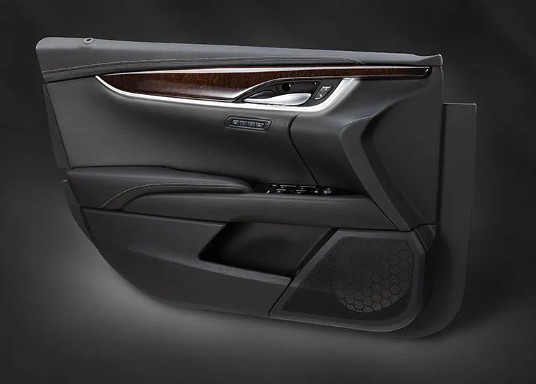
INPUT
The given input is a 'Class A' suface of the side Door trim panel with the Master sections for attachment features and Designing references.
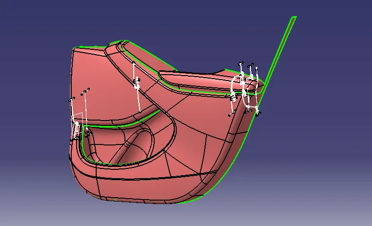
It consists of 4 main components
1.Door arm Rest
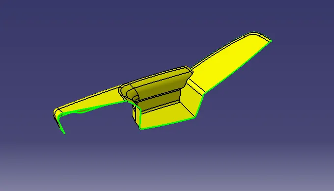
2.Map Pocket
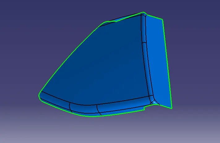
3.Bottle Holder
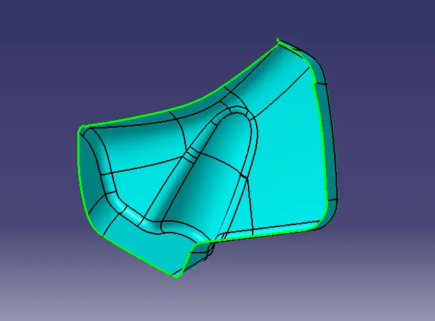
4. Lower Substrate
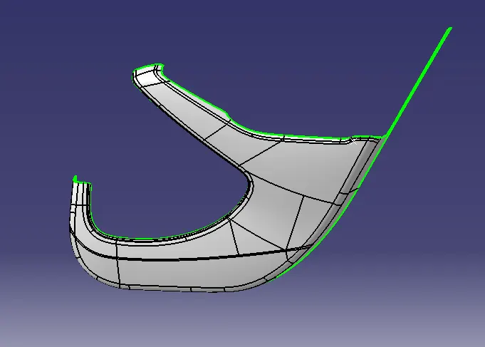
Tooling axis
Tooling is the direction of which the component is the manufactured in a plastic injection Moulding. It is found by performing draft analysis on the Class A component and is created usually perpendicular to the component.
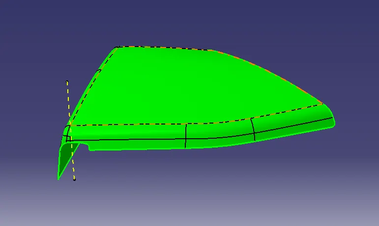
(yellow line is the tooling axis of the Map pocket which clears the minimum draft angle of 3 Degrees )
Similarly, its created for Bottle holder, door arm rest and lower substrate.
CLASS B- Surface
It is the Engineering Surface of a Component and one of the outer surface of a thickened component. Here it is offseted from Class A for 2.5mm which is the thickness of the component feature by feature.
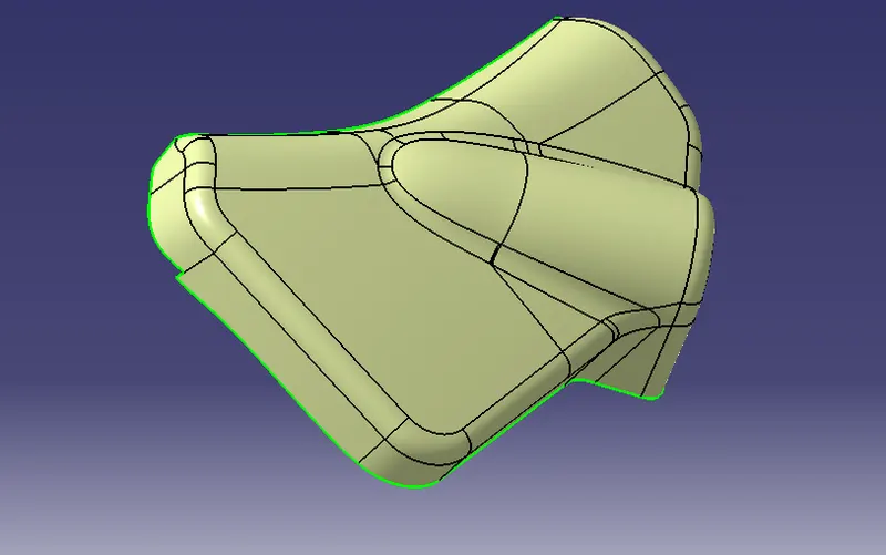
CLASS C- Surface
Its created based on the Tooling axis and Reference surface from Class A/B to to close the gap between Class A and Class B to produce a close body surface.
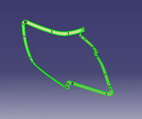
(C-surface of Bottle holder)
Class A , Class B and Class C are the joined together to create the close body solid component.
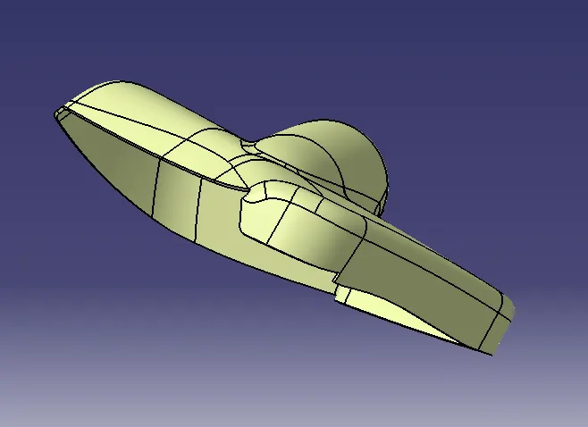
(Closed Body of the Bottle Holder)
Similarly, it is created for the Map pocket, Doorm arm rest and Lower Substrate.
Engineering Feature Creation:
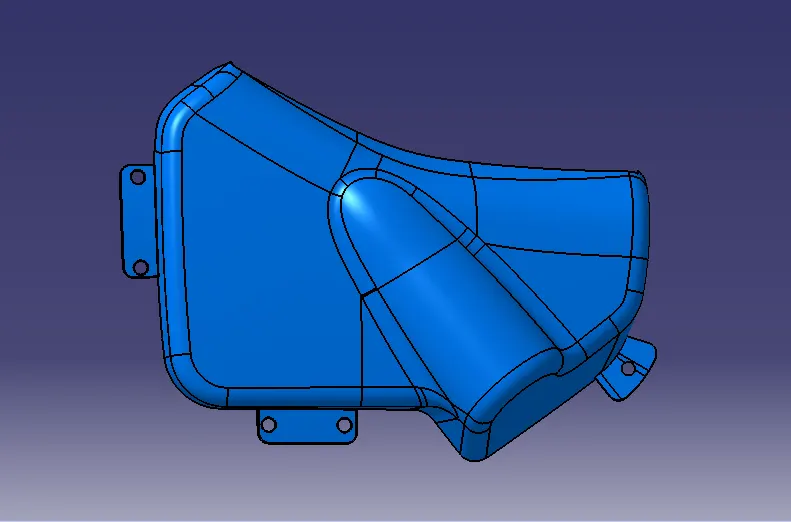
Flanges are created to Door arm rest, bottle holder and map pocket as attachment feature to get attached with Lower substrate with Master Section as reference.
Door Arm Rest with Flanges
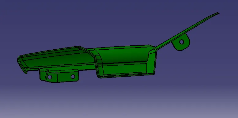
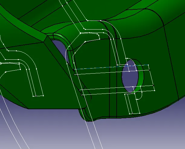
(Flanges created matching the reference master section)
Map pocket with Flanges
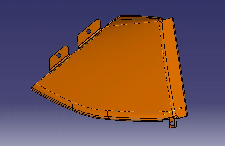
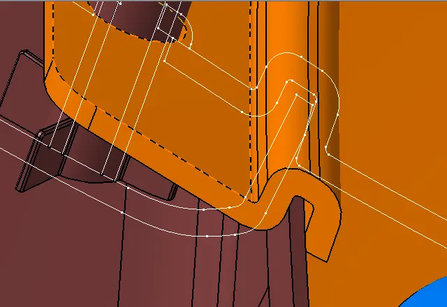
(Flanges of the Map pocket created matchig with the Master section and lower substrate)
Bottle holder with Flanges
Lower Substrate
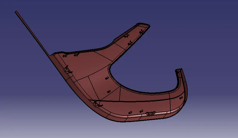
All the attachment features such as Heat stakes, Ribs and Dog House are created in the lower substrate.
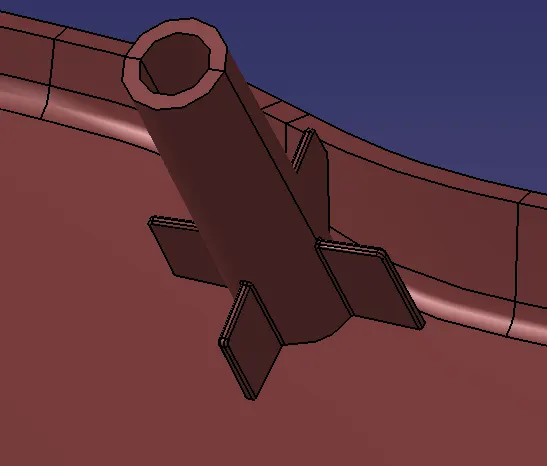
(Heat Stakes are created with respect to the attachment flanges of the attaching component)
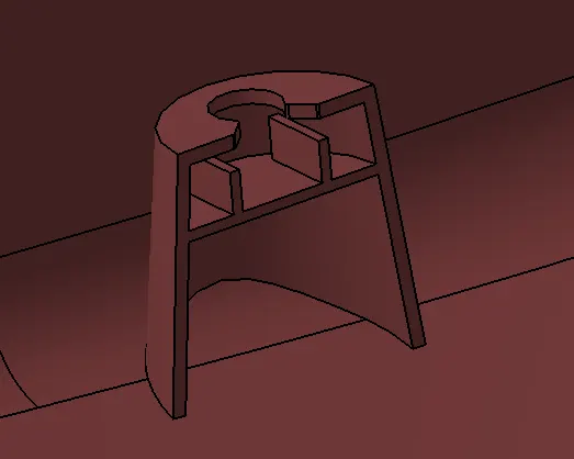
(Dog house is created for the push pin attachment from which the exterior Sheet metal panel comes and get fixed)
Lower Substrate with Attachment Features
DRAFT ANALYSIS
In the plastic injection moulding, it is difficult for ejection of the cavity which is parallel to the cooled solid part due to friction which casuses deformity in the suface of the part. Hence, a draft angle is provided for easy ejection avoiding surface deformity. As designers, we provide draft angle while creating Class B and Class C surface.
Draft Analysis is made to each component to check if the features get cleared with minimum draft angle.
Bottle holder
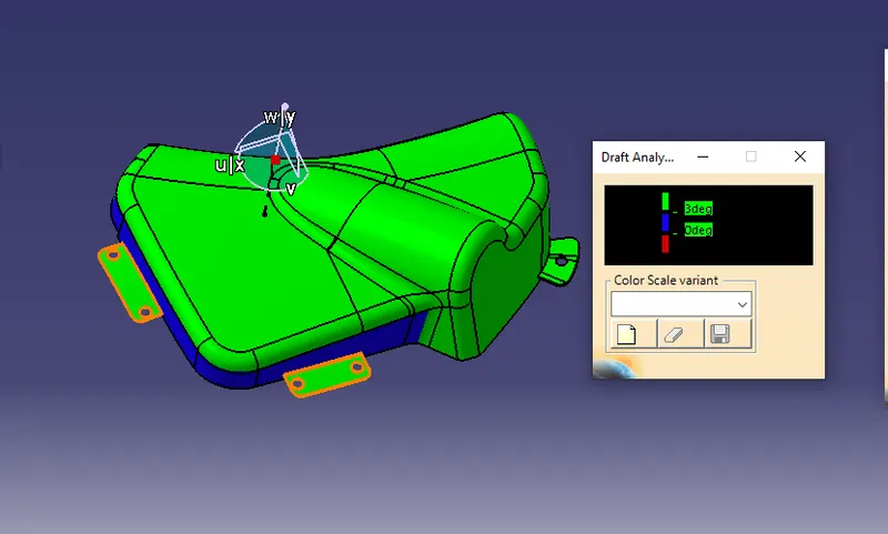
(All the features clearing minimum draft of 3 degrees is in green. Blue color in dicates inverse draft angle and it is notified to the 'Class A' surface designer to change the class surface in order to clear the draft angle)
Map pocket
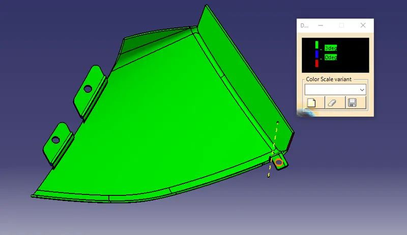
(It cleared the minium draft clearance for 3 degrees)
Door arm
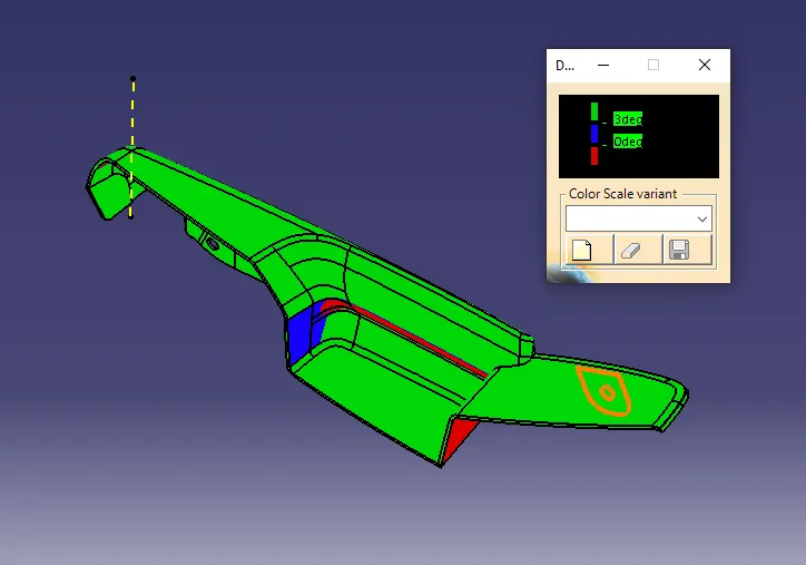
(Inside faces are cleared with another tooling axis horizontal/ pendicular to main yellow tooling axis line since it is complex part and cannot be tooled with single tooling direction.)
Heat stakes
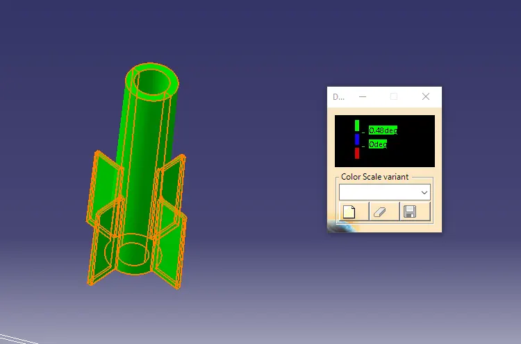
(It is created with draft of 0.5 degrees and cleared in draft analysis)
Dog House
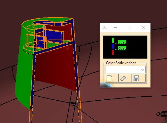
(Tooling Axis Vertical which clears the outer features of dog house for minimum draft angle)
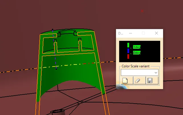
(Tooling Axis horizontal/perpendicilar to inner suface and is cleared for minimum draft angle)
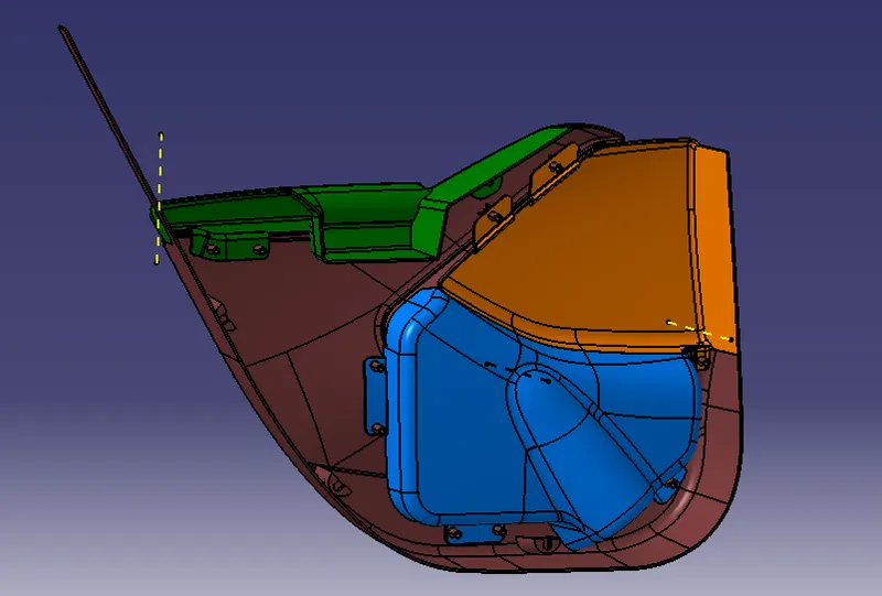
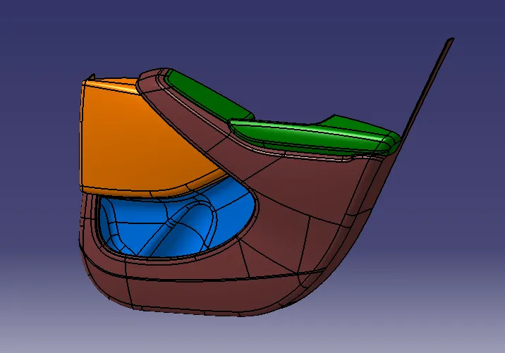
FINAL ASSEMBLY
Finally the Parts are assembled in Assembly workbench.
RESULT
- CLASS A, B & C are created as per Industry standards
- B- Side features are designed as per design rules for attachment
- Draft analysis was performed for the model to check the feasibility for manufacturing which is under permisible limit.