Creation of geometries by Coordinate system methods using AutoCad
AIM:
- To create the geometries from P1 to P2 using all the coordinate system methods. If required, we need to use the line tool to create the geometries and circle tool. The imperial template and the decimal units are used to draft the features.
- To draw the civil-related profile and the trusses shown above using any coordinate system methods. ( Dimensions are for reference).
INTRODUCTION:
AutoCAD is a drafting tool used in the architecture, engineering, and construction field across all stages of the construction process. Engineers use this software tool to plan, draw, execute, and study the strength and properties of a building and its components.
Coordinate System: AutoCAD uses some types of coordinate systems to locate the data at fixed coordinates. They are:
- Absolute coordinate system: We type X and Y coordinates to locate the point relative to the origin.
- Relative coordinate system.
- Relative rectangular coordinate system: This method allows us to specify position along the X, Y and Z axis to locate a point relative to the last point we specified.
- Relative polar coordinate system: Polar coordinate system is used in navigation as the destination or direction of travel can be given as an angle and distance from the object being considered.
- Direct distance entry system: This entry enables us to draw an object, such as a line, by pointing in a particular direction with the cursor and entering a distance at the command line.
Commands used:
- Line command.
- Circle command.
- Dimlinear command.
- Eraser command.
- Text command.
PROCEDURE:
- Start the AutoCAD 2023 software from the start menu or desktop.
- Click on START DRAWING.
- In the command line type: STARTUP and enter.
- Enter new value of startup: 1
- Go to the application menu and select new.
- In the 'Create New Drawing' dialogue box, select the 'Imperial system in the start from Scratch' option.
- Next, select the 'Decimal using system' from the 'Advanced Setup' option
- Set the limits by entering LIMITS in the command tab. The lower-left corner is specified as 0,0 and the upper-right corner is specified as 100,100.
- The above procedure is followed every time a new drawing is to be created.
1. To create the geometry from P1 and P2 using all the coordinate system methods.
- Drafting the geometry for P1 using all coordinate system methods:
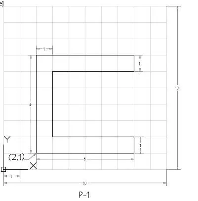
- Absolute coordinate system:
- Enter line command and specify the starting point 1 as 2,1
- Specify the NEXT following points:
- Point 2: 8,1
- Point 3: 8,2
- Point 4: 3,2
- Point 5: 3,6
- Point 6: 8,6
- Point 7: 8,7
- Point 8: 2,7
- And then for the last point type C and close the geometry.
RESULT: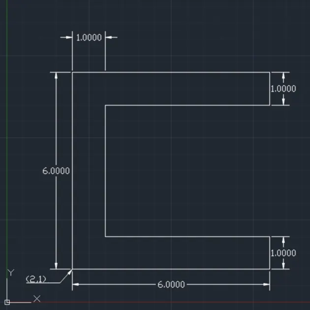
- Relative coordinate system:
- Relative rectangular coordinate system:
- Select the line tool from the ribbon tab.
- Specify starting point1 as 2,1.
- Specify the next points in order as follow:
- Point 2 as @6,0
- Point 3 as @0,1
- Point 4 as @-5,0
- Point 5 as @0,4
- Point 6 as @5,0
- Point 7 as @0,1
- Point 8 as @-6,0
- Then for the last point 9 as @0,-6 and then press the 'ESC' key to close the geometry.
RESULT:
- Relative polar coordinate system:
- Enter the line in the command bar and select the line tool.
- Specify starting point 1 as 2,1
- Specify the next points in order as followed:
- Point 2 as @6<0
- Point 3 as @1<90
- Point 4 as @5<180
- Point 5 as @4<90
- Point 6 as @5<0
- Point 7 as @1<90
- Point 8 as @6<180
- Point 9 as @6<270
- Click on the 'ESC' to close the geometry.
RESULT:
- Relative rectangular coordinate system:
- Direct distance entry method:
- Enter 'Line' in the command bar and select line command.
- Shift to ORTHO mode for this method.
- Specify first point 1 as 2,1
- And then direct the cursor to desired directions for plotting the next points.
- Direct the cursor to follow directions and specify the distance of the line concerning the order:
- Point 2: right, 6
- Point 3: up, 1
- Point 4: left, 5
- Point 5: top, 4
- Point 6: right, 5
- Point 7: top, 1
- Point 8: left, 6
- And then enter the 'CLOSE' command to close the geometry.
RESULT:
- Absolute coordinate system:
- Drafting the geometry for P2 using all coordinate system methods:
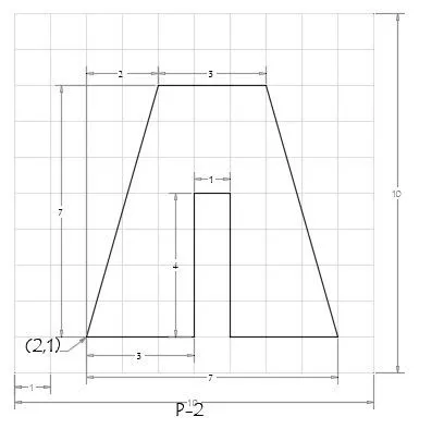
- Absolute coordinate method:
- Enter line command and specify the starting point 1 as 2,1
- Specify the NEXT following points:
- Point 2: 5,1
- Point 3: 5,5
- Point 4: 6,5
- Point 5: 6,1
- Point 6: 9,1
- Point 7: 7,8
- Point 8: 4,8
- And then for the last point type C and close the geometry using the close command.
RESULT: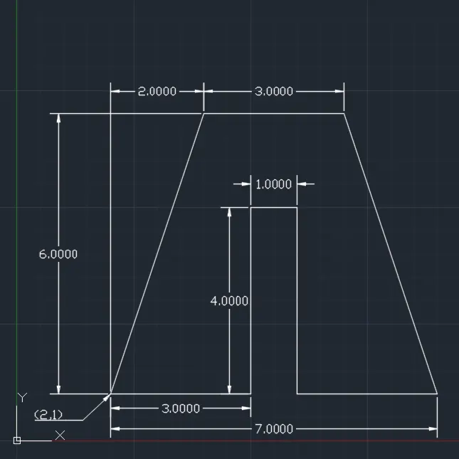
- Relative coordinate method:
- Relative rectangular coordinate method:
- Select the line tool from the ribbon tab.
- Specify starting point 1 as 2,1.
- Specify the next points in order as follow:
- Point 2 as @3,0
- Point 3 as @0,4
- Point 4 as @1,0
- Point 5 as @0,-4
- Point 6 as @3,0
- Point 7 as @-2,7
- Point 8 as @-2,0
- Then for the last point 9 as @-2,-7 and then press the 'ESC' key to close the geometry.
RESULT:
- Relative Polar coordinate method:
- Enter the line in the command bar and select the line tool.
- Specify starting point 1 as 2,1
- Specify the next points in order as followed:
- Point 2 as @3<0
- Point 3 as @4<90
- Point 4 as @1<0
- Point 5 as @4<270
- Point 6 as @3<0
- Point 7 as @7<106
- Point 8 as @3<180
- Point 9 as @7<254
- Click on the 'ESC' to close the geometry.
RESULT:
- Relative rectangular coordinate method:
- Direct distance entry method:
- Enter 'Line' in the command bar and select line command.
- Shift to ortho mode for this method.
- Specify first point 1 as 2,1
- And then direct the cursor to desired directions for plotting the next points.
- Direct the cursor to follow directions and specify the distance of the line concerning the order:
- Point 2: right, 3
- Point 3: top, 4
- Point 4: right, 1
- Point 5: bottom, 4
- Point 6: right, 3
- Point 7: @-2,7 ( relative coordinate method, because it's not possible in this method )
- Point 8: left, 3
- And then use the close command to complete the geometry.
RESULT:
- Absolute coordinate method:
- Drafting the geometry for P3 using an absolute coordinate system:
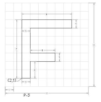
- Use line command and specify first point 1 as 2,1
- Specify the following points in order:
- Point 2: 3,1
- Point 3: 3,3
- Point 4: 6,3
- Point 5: 6,4
- Point 6: 3,4
- Point 7: 3,7
- Point 8: 8,7
- Point 9: 8,8
- Point 10: 2,8
- Use the close command to close the geometry.
RESULT: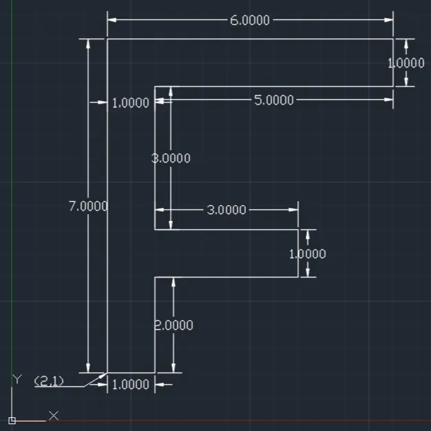
- Drafting the geometry for P4 using the relative rectangular coordinate system:
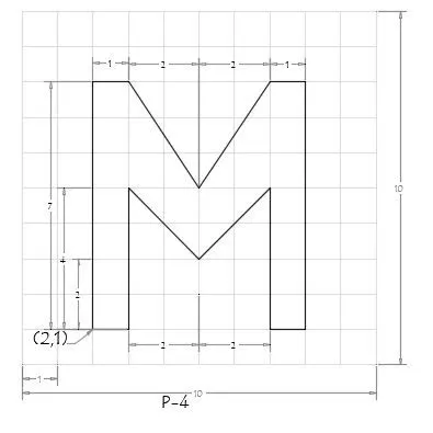
- Using the line command start the line and specify starting point 1: 2,1
- Specify the following points in order:
- Point 2: @0,7
- Point 3: @1,0
- Point 4: @2,-3
- Point 5: @2,3
- Point 6: @1,0
- Point 7: @0,-7
- Point 8: @-1,0
- Point 9: @0,-4
- Point 10: @-2,-2
- Point 11: @-2,2
- Point 12: @0,-4
- Point 13: @-1,0
- And then enter 'ESC' to close the geometry.
RESULT: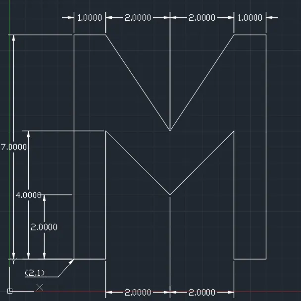
- Drafting the geometry for P5 using the relative polar coordinate system:
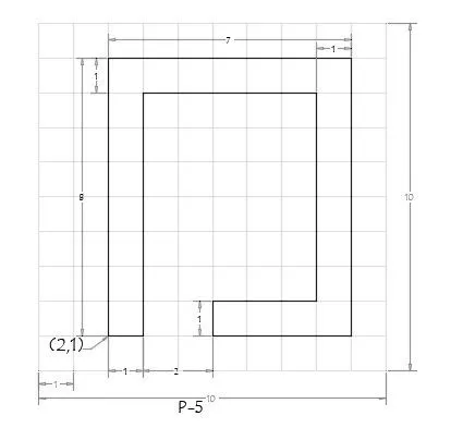
- Using line command start line and specify first point 1: 2,1
- Specify the following points in order:
- Point 2: @1<0
- Point 3: @7<90
- Point 4: @5<0
- Point 5: @6<270
- Point 6: @3<180
- Point 7: @1<270
- Point 8: @4<0
- Point 9: @8<90
- Point 10: @7<180
- And then use the close command to close the geometry.
RESULT: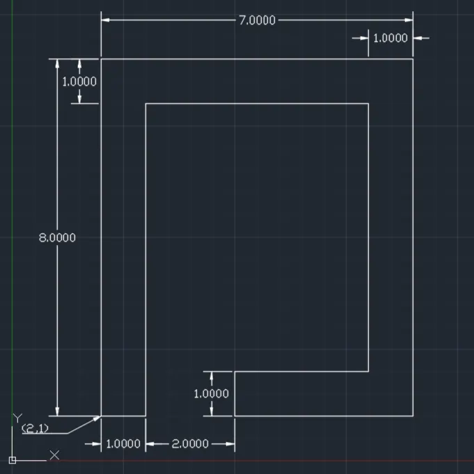
- Drafting the geometry for P6 using the relative rectangular coordinate method:
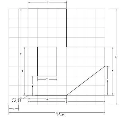
- Specify the first point 1 as 2,1 using the line command.
- Specify the following points in order:
- Point 2: @4,0
- Point 3: @4,3
- Point 4: @0,2
- Point 5: @-4,0
- Point 6: @0,4
- Point 7: @-4,0
- And close the outer geometry using the close command.
- Start inner geometry with the new line and specify point 1 as 3,3
- Specify the following points in order:
- Point 2: @2,0
- Point 3: @0,3
- Point 4: @-2,0
- Use the close command to close the geometry.
RESULT: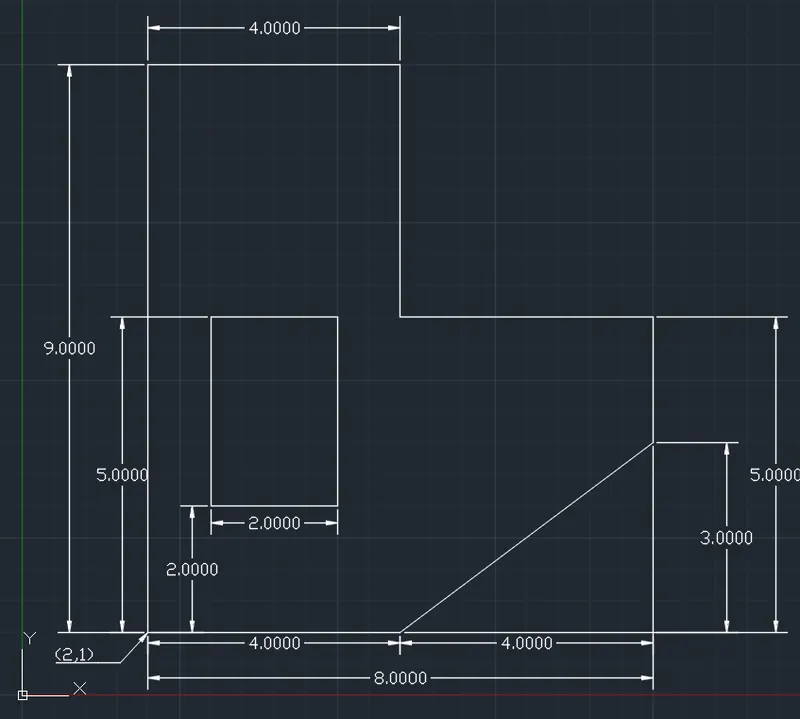
- Drafting the geometry P7 using the direct distant entry method:
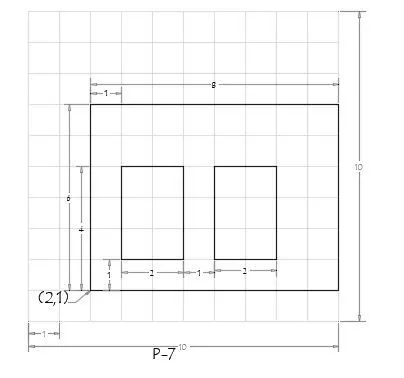
- Using line command specify first point 1: 2,1
- Specify the following points in order:
- Point 2: right, 8
- Point 3: top, 6
- Point 4: left, 8
- and then close that geometry.
- Using line command for first internal geometry specify first point 1: 3,2
- Specify the following points in order:
- Point 2: right, 2
- Point 3: top, 3
- Point 4: left, 2
- and then close the geometry.
- Using line command for 2nd internal geometry specify first point 1: 6,2
- Specify the following points in order:
- Point 2: right, 2
- Point 3: top, 3
- Point 4: left, 2
- And then close the geometry.
RESULT: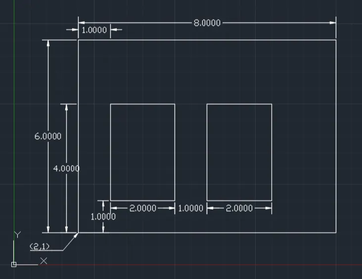
- Drafting the geometry of P8 using the direct distance entry method:
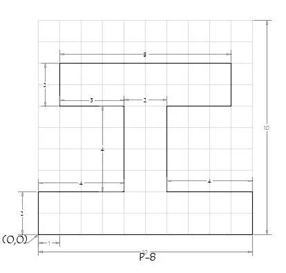
- Using the line command specify the first point as 0,0
- Specify the following points in order:
- Point 2: right 10
- Point 3: top 2
- Point 4: left 4
- Point 5: top 4
- Point 6: right 3
- Point 7: top 2
- Point 8: left 8
- Point 9: bottom 2
- Point 10: right 3
- Point 11: bottom 4
- Point 12: left 4
- And then use the close command to close the geometry.
RESULT: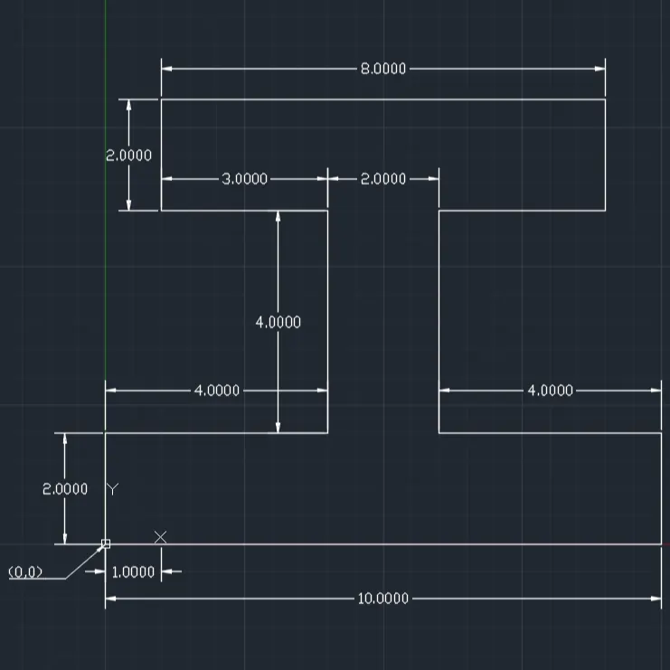
- Drafting the geometry P9 using the relative rectangular method:
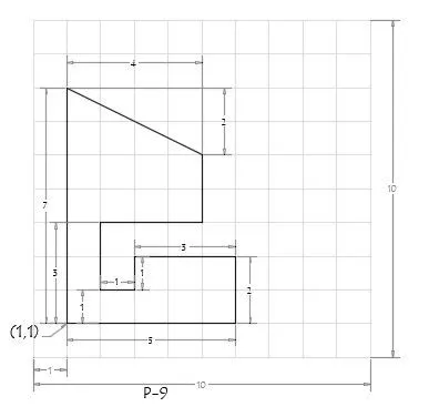
- Using line command specify Point 1 as 1,1
- Specify the next following points in order:
- Point 2 @ 5,0
- Point 3 @ 0,2
- Point 4 @ -3, 0
- Point 5 @ 0,-1
- Point 6 @ -1,0
- Point 7 @ 0,2
- Point 8 @ 3,0
- Point 9 @ 0,2
- Point 10 @ -4,2
- Point 11 @ 0,-7
- And then use the close command to complete the geometry
RESULT: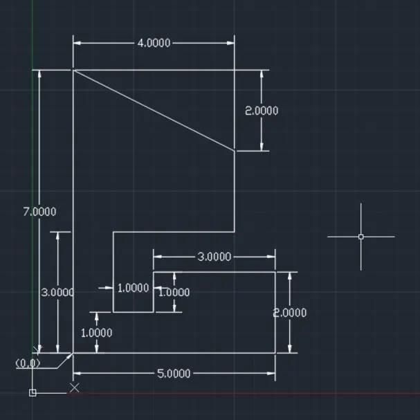
- Drafting the geometry P10 using the absolute coordinate method:
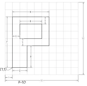
- Using the line command start line at point 1 as 1,1
- Specify the following points in order:
- Point 2 as 3,1
- Point 3 as 4,3
- Point 4 as 6,4
- Point 5 as 6,8
- Point 6 as 1,8
- Point 7 as 1,1 and then close external geometry
- Specify the first point 1 of internal geometry as 2,5
- Specify the following points in order:
- Point 2 as 5,5
- Point 3 as 5,7
- Point 4 as 2,7
- Point 5 as 2,5 and then close the internal geometry
- Use the close command.
RESULT: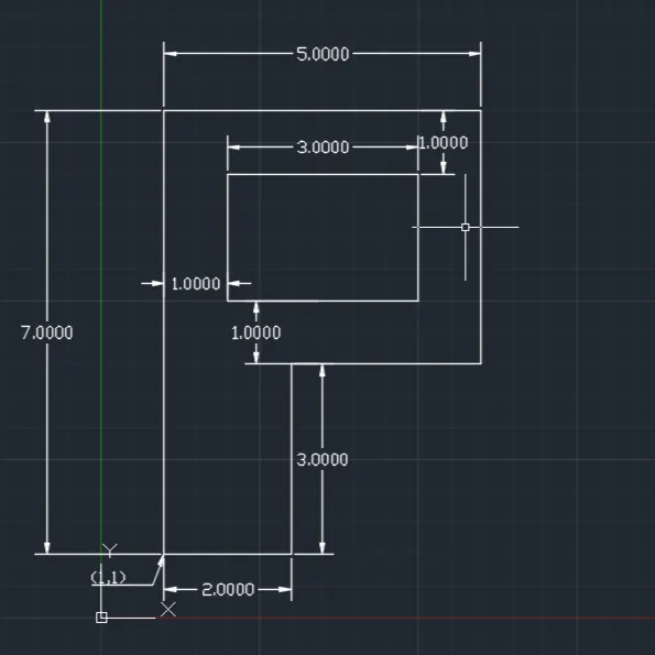
2. To draw the civil-related profile and the trusses using any coordinate system methods:
- Drawing Profile- wood using absolute co ordinate method:
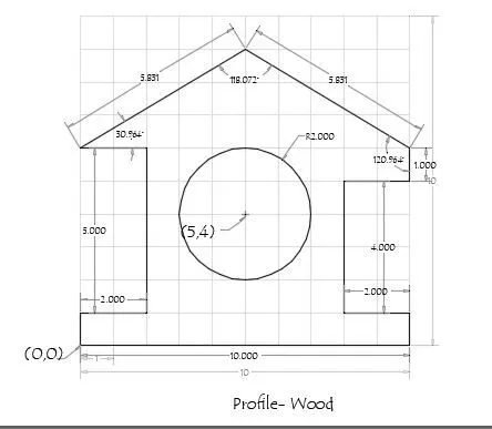
- Using line command, specify first point 2 as 0,0
- Specify next following points in order:
- Point 2 as 0,1
- Point 3 as 2,1
- Point 4 as 2,6
- Point 5 as 0,6
- Point 6 as 5,9
- Point 7 as 10,6
- Point 8 as 8,5
- Point 9 as 8,1
- Point 10 as 10,1
- Point 11 as 10,0
- And then close the external wood.
- Use circle command and specify centre as 5,4
- And specify radius as 2
RESULT: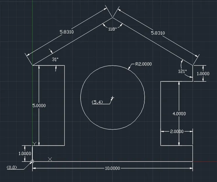
- Drawing Queen Post Truss (Truss 1) :
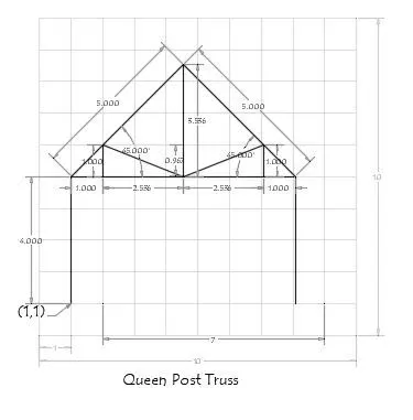
- Using line command specify first point 1 as 1,1
- Specify the next points as follows to make a frame:
- Point 2 @4<90
- Point 3 @5<45
- Point 4 @5<315
- Point 5 @4<270 and click on 'ESC'
- Using line command by direct distance entry consider the first point as point 2 and specify point 6 @ right,1
- From point 6 specify point 7 @ top, 1 and click 'ESC'
- Using line command by direct distance entry consider the first point as point 4 and specify point 8 @ left, 1
- From point 8 specify point 9 @ top, 1 and click 'ESC'
- Using line command and the first point as 3 specify point 10 that straight bottom to point 3 and at exact middle to point 2 and 4 using guild lines.
- Join the points 6-10, 7-10, 3-10, 9-10, 8-10 using the line command.
RESULT: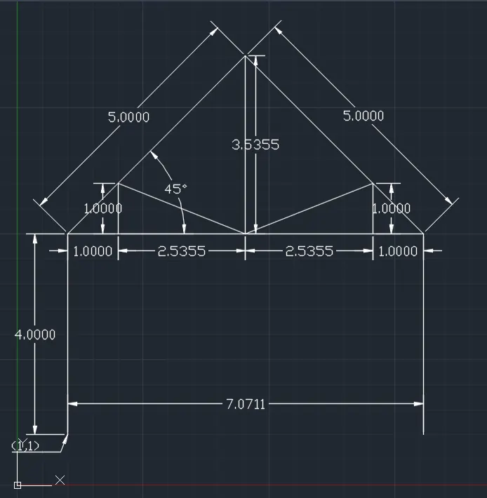
- Drawing howe truss (Truss 2):
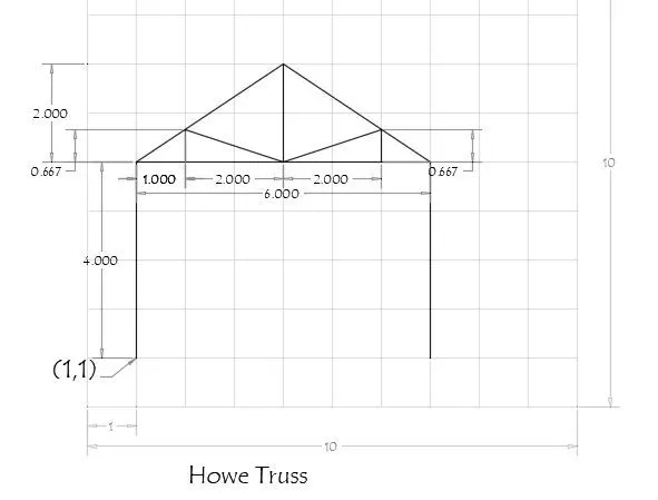
- Using line command specify first point 1 as 1,1 and specify the next points as follows:
- Point 2 @4<90
- Point 3 @1<0
- Point 4 @2<0
- Point 5 @2<0
- Point 6 @1<0
- Point 7 @4<270 and click on 'ESC'
- Using the line command specify the first point as 3 and specify the next point 8 @1<90 and click on 'ESC'.
- Using the line command specify the first point as 4 and specify the next point 9 @2<90 and click on 'ESC'.
- Using the line command specify the first point as 5 and specify the next point 10 @1<90 and click on 'ESC'.
- Using the line command join points 8-4-10, 2-8-9-10-6.
RESULT: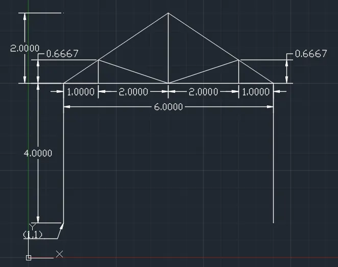
- Using line command specify first point 1 as 1,1 and specify the next points as follows:
- Drawing Flat truss (Truss 3):
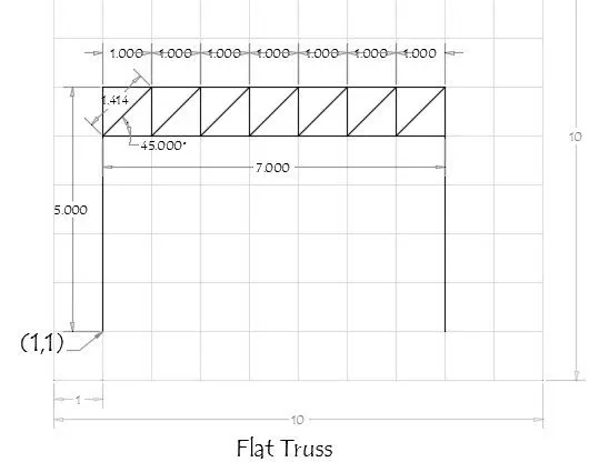
- Using the line command specify the first point 1 as 1,1 and specify the next points as follow:
- Point 2 @4<90
- Point 3 @1,0
- Point 4 @1,0
- Point 5 @1,0
- Point 6 @1,0
- Point 7 @1,0
- Point 8 @1,0
- Point 9 @1,0
- Point 10 @4<270 and enter 'ESC'
- Using line command specify the first point as point 2 and specify the next points as follows:
- Point 11 @1<90
- Point 12 @1,0
- Point 13 @1,0
- Point 14 @1,0
- Point 15 @1,0
- Point 16 @1,0
- Point 17 @1,0
- Point 18 @1,0 and enter 'ESC'.
- Using the line command join the following points:
- 2-12
- 12-3
- 3-13
- 13-4
- 4-14
- 14-5
- 5-15
- 15-6
- 6-16
- 16-7
- 7-17
- 17-8
- 8-18
- 18-9 and escape
RESULT: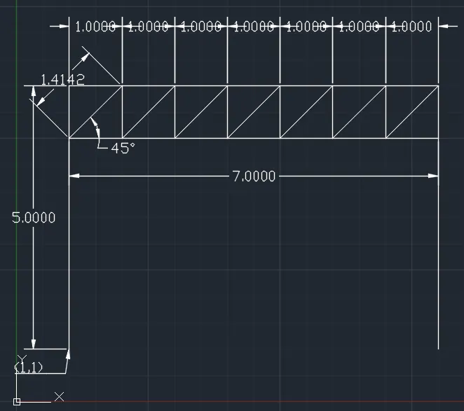
- Using the line command specify the first point 1 as 1,1 and specify the next points as follow:
- Draw MONO Pitch (Truss 4):
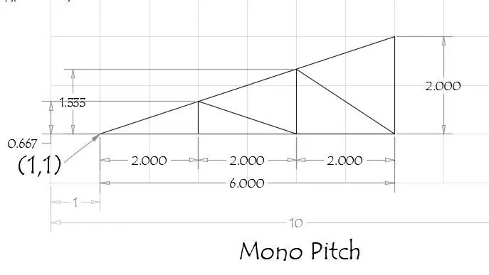
- Using the line command specify the first point as 1,1 and specify the next points as follow in order:
- Point 2 @ 2<0
- Point 3 @ 2<0
- Point 4 @ 2<0
- Point 5 @ 2<0
- And close the external frame with the close command.
- Draw the line 90 degrees from point 2 and point 3 up to the slope line of the truss and consider the joining points as point 7 and point 6
- Then with line command join point 7-3 and point 6-4
- The MONO PITCH is formed.
RESULT: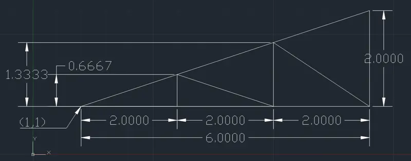
- Using the line command specify the first point as 1,1 and specify the next points as follow in order: