Creating a Floor plan, Footing detail and Isometric view using AutoCad
In this challenge, 6 geometries are provided and different aims are provided for respective geometries.
1:
AIM: To create the cross-section of load bearing wall over spread footing.
Introduction: This is created in AutoCAD using the following commands:
- Line
- Polyline : It is a connected sequence of line segments that are created as a single object.
- Rectangle
- Eraser
PROCEDURE:
- First, use the rectangle command to make the base rectangle i.e, 0.9 X 0.25
- Select rectangle from ribbon tab and specify the first point as 1,1
- Select the dimension option from the rectangle and give:
- Length = 0.9
- Width = 0.25
- After that use the polyline command to draw on a rectangle ( creating steps for footing).
- Select the polyline tool from the ribbon tab and specify the first point 1 as the top left corner of the existing rectangle using the snap cursor.
- And create a polyline by specifying the remaining points as follow.
- Point 2 @0.2<0
- Point 3 @0.4<90
- Point 4 @0.05<0
- Point 5 @0.4<90
- Point 6 @0.4<0
- Point 7 @0.4<270
- Point 8 @0.05<0
- Point 9 @0.4<270 and click on 'ESC'
- Creating left rectangle i.e, 1.15 x 0.15
- Using a rectangle from the ribbon tab create a rectangle by giving dimensions:
- Length = 1.15
- Width = 0.15
- Using a rectangle from the ribbon tab create a rectangle by giving dimensions:
- Create steps on that using polyline.
- Use the polyline command from the ribbon tool and start by specifying point 1 as top left corner of that rectangle.
- Point 2 @0.3<0
- Point 3 @0.15<90
- Point 4 @0.3<0
- Point 5 @0.15<90
- Point 6 @0.3<0
- Point 7 @0.15<90
- Point 8 @0.3<0
- Point 9 @0.15<90
- Point 10 @0.05<90
- Point 11 @1<90
- Point 12 @0.3<0
- Point 13 @1<270
- Point 14 @0.05<270
- Point 15 @0.6<270 and the click on 'ECS'.
- Use the polyline command from the ribbon tool and start by specifying point 1 as top left corner of that rectangle.
- The required cross-section of Load bearing wall over spread footing is created.
RESULT: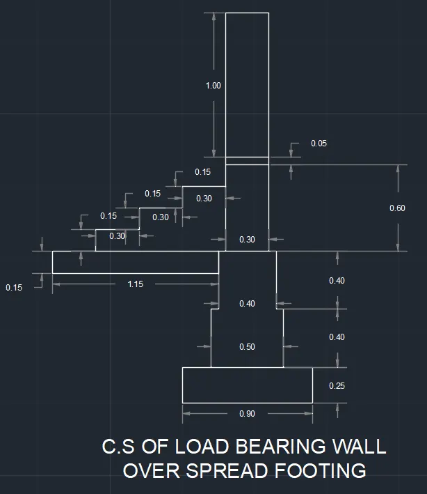
2:
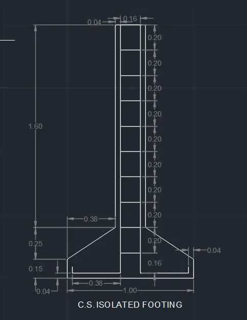
AIM: To create the Cross Section of Isolated Footing.
INTRODUCTION: Commands and modification tools which are used for this geometry are:
- Polyline
- Copy
- Array
PROCEDURE:
- Select polyline to create outer geometry
- ribbon tool < draw < Polyline
- Start at point 1 as 1,1
- And specify the next points as follow:
- Point 2 @0.15<90
- Point 3 @0.38,0.25
- Point 4 @0,1.6
- Point 5 @0.2,0
- Point 6 @0,-1.6
- Point 7 @0.38,-0.25
- Point 8 @0,-0.15
- Point 9 @-1,0
- Enter C to close the outer geometry.
- To create steel reinforcement inside the outer geometry again start polyline.
- Start at @0.04,0.09 from the bottom left corner of outer geometry.
- And specify the next points as follow:
- Point 2 @0,0.05
- Point 3 @0.38<0
- Point 4 @0.16<90
- Point 5 @0.16<0
- Point 6 @0.16<270
- Point 7 @0.38<0
- Point 8 @0,0.05 and press 'ESC' to end polyline
- For creating stirrups on the base reinforcement we are going to use Copy < Array tool
- First draw polyline on the base reinforcement
- Point 1 On the top left corner of the middle reinforcement
- Point 2 @0.2<90
- Point 3 @0.16<0
- Point 4 @0.2<270 and press 'ESC' to end it
- Then from Modify tab in the ribbon tab select copy option.
- Select the object-polyline that has been created now
- Select the bottom left corner of the polyline as a base point.
- Select the array option from the copy.
- Give the number of items= 9
- And copy it one up on one equally.
- Click 'ESC'
- First draw polyline on the base reinforcement
- The cross-section of ISOLATED FOOTING is created.
RESULT:
3.
AIM: To create a line diagram / Floor plan of two bedroom building
INTRODUCTION: In this layout, we are going to use the below commands and modifiers
- Polyline
- Line
- Copy
PROCEDURE:
- First, select polyline command and specify first point 1 at 1,1
- For the rest follow the points in order:
- Point 2 @0,3.6
- Point 3 @3.6,0
- Point 4 @0,0.3
- Point 5 @0,0.3
- Point 6 @0,0.3
- Point 7 @1,0
- Point 8 @0,-0.3
- Point 9 @0,-0.3
- Point 10 @0,-0.3
- Point 11 @4.2,0
- Point 12 @0,-3.6
- Point 13 @-4.2,0
- Point 14 @0,-0.3
- Point 15 @0,-0.3
- Point 16 @0,-0.3
- Point 17 @-1,0
- Point 18 @0,0.3
- Point 19 @0,0.3
- Point 20 @0,0.3
- Point 21 @-3.6,0 and enter 'ESC' to close the geometry
- And then take the line tool and draw the horizontal line of 1 unit from point 18 to point 15
- Copy that line from copy command from modifying tab of the ribbon tab
- Select Multiple options
- Copy that line to Point 19, Point 4, and Point 5 and click on 'ESC'
- The floor plan of Two bedrooms is Created in Auto CAD
RESULT: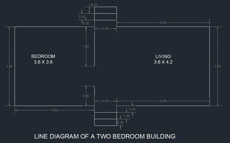
4.
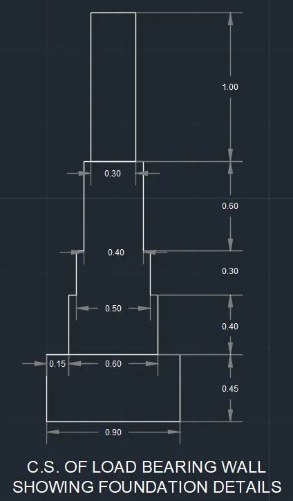
AIM: To create the cross-section of the load-bearing wall showing foundation details.
INTRODUCTION: This is created with the use of the following commands:
- Line
- Polyline
- Rectangle
- Eraser
PRODUCER:
- First, use the rectangle (REC) command to create the base rectangle
- Specify first point 1 as 1,1 and dimensions as:
- Length = 0.90
- Width = 0.45
- And use polyline to create the steps of footing:
- Point 1 is the top left corner of the base rectangle
- Point 2 @0.15<0
- Point 3 @0.40<90
- Point 4 @0.05<0
- Point 5 @0.30<90
- Point 6 @0.05<0
- Point 7 @0.60<90
- Point 8 @0.40<0
- Point 9 @0.60<270
- point 10 @0.05<0
- Point 11 @0.30<270
- point 12 @0.05<0
- Point 13 @0.40<270 and Press 'ESC' to close the geometry.
- Use rectangle to create a rectangle on top of the footing
- Specify starting point @0.05,0 from the top left end of step footing with dimensions:
- length=0.30
- width=1.00
- Specify starting point @0.05,0 from the top left end of step footing with dimensions:
- Specify first point 1 as 1,1 and dimensions as:
RECTANGLE:
5.
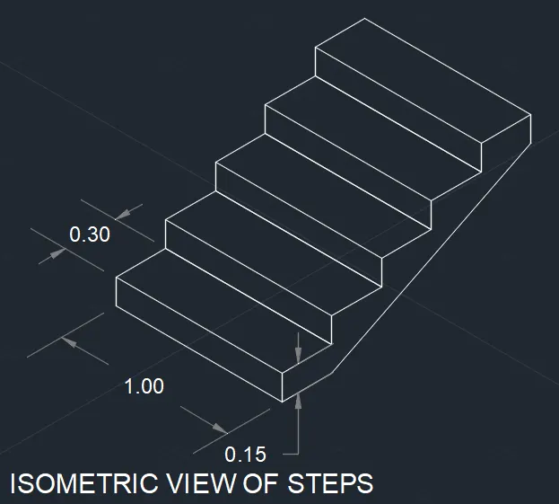
AIM: To create an ISOMETRIC view of steps in AutoCAD 2D
INTRODUCTION: In this geometry, we will introduce the new command known as ISODRAFT.
It can be found in AutoCAD's status bar ( bottom right corner ) or we can use the ISODRAFT command to jump into the isometric 2D view.
And the other commands that are used are :
- Line
- Polyline
- isoplane Left
- isoplane Right
- isoplane Top
- Copy
- Array
- Ortho
PROCEDURE:
- Turn on Isodraft view and ortho mode from the status bar
- Go to Isoplane left and follow the following steps
- Go to polyline to create the riser of the stairs and start point 1 at 1,1 and make the isometric rectangle with a length of 1.00 and height of 0.15.
- Go to the Isoplane top to create a thread and start the polyline at the left corner of the riser with a width of 0.30 and a length of 1.00
- Copy this geometry which has been completed and copy it using the copy tool
- Use an array to make multiple copies.
- Mention no of item=5
- Copy step by step.
- Go to Isoplane right:
- Start line of 0.30 at the bottom end of the first riser and end it.
- Start line of 0.15 at the top end of the top thread and end it.
- Join both ends using the line command.
- The staircase is created.
RESULT:
6.
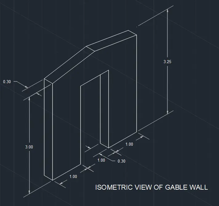
AIM: To Create the isometric view of GABLE WALL using AutoCAD 2D
INTRODUCTION: The commands that are used are :
- Line
- Polyline
- Isodraft
- isoplane Left
- isoplane Right
- isoplane Top
- Copy
- Array
- Ortho
PROCEDURE: Start with the ISODRAFT command:
- Go to Isoplane left and start polyline to create the thickness of at 1,1 and create with height and thickness of
- Height= 3.00
- Thickness= 0.30
- Go to Isoplane right view and start the polyline to create the front face of the wall as shown in the figure with ortho on.
- Point 1 1,1
- Point 2 1 to right
- Point 3 2.42 to top
- Point 4 1 to right
- Point 5 2.42 to bottom
- Point 6 1 to right
- Point 7 3 to top and close the geometry.
- Go to Isoplane left and provide thickness inside the opening.
- Turning off ortho provides the upper triangle as per dimensions.
RESULT: