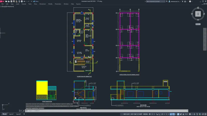
Project 1 _Creating an Architectural plan for the provided plot size and develop relevant basic structural drawings
AIM: To design and Draft a layout of a residential building of plot size 60'x20' with east facing by developing an architectural floor plan, elevations, sections and Structural drawings (column, beam and footing plan)
INTRODUCTION:
Creating a residential plan and making it understandable requires additional drawing. They are :
- Floor plan
- Structural plan:
- Beam plan
- Column plan
- Footing plan
- Architectural Elevation designs
- Sections at required levels
Some of the Commands and tools which are used for designing this drawing are:
- line
- xline
- polyline
- layers
- hatches
- dimensions
- annotations
- fillets
- curves
- blocks
- leaders
- texts
- colours
- linetypes
- scale
- trim
- extend
- erase
- UNITS
and many
PROCEDURE:
The text height used is 9" in maximum cases.
While starting the drawing the initial thing we have to do is select the unit and change it into feet (engineering)
After that create the layers and mentions those properties as follows:
Name Status On Freeze Lock Plot Color Linetype Lineweight Transparency New VP FreezeDescription
| 0 | kUsed | True | False | False | True | white | Continuous | ByLineWeightDefault | 0 | False | ||
| ANNOTATIONS | kUsed | True | False | False | True | white | Continuous | ByLineWeightDefault | 0 | False | ||
| BEAMS | kUsed | True | False | False | True | 210 | Continuous | ByLineWeightDefault | 0 | False | ||
| columns | kUsed | True | False | False | True | 242 | Continuous | ByLineWeightDefault | 0 | False | ||
| Defpoints | kUsed | True | False | False | False | white | Continuous | ByLineWeightDefault | 0 | False | ||
| DIMENSIONS | kUsed | True | False | False | True | 9 | Continuous | ByLineWeightDefault | 0 | False | ||
| DOORS | kUsed | True | False | False | True | 104 | Continuous | ByLineWeightDefault | 0 | False | ||
| exterior wall | kUsed | True | False | False | True | 50 | Continuous | ByLineWeightDefault | 0 | False | ||
| FLOORING | current | True | False | False | True | 130 | Continuous | ByLineWeightDefault | 0 | False | ||
| FOOTING | kUsed | True | False | False | True | 8 | Continuous | ByLineWeightDefault | 0 | False | ||
| HATCH | kUsed | True | False | False | True | 8 | Continuous | ByLineWeightDefault | 0 | False | ||
| PROJECTORS | kUsed | False | False | False | True | 251 | DASHED | ByLineWeightDefault | 0 | False | ||
| SECTION LINE | kUsed | True | False | False | True | 60 | JIS_08_11 | ByLineWeightDefault | 0 | False | ||
| STAIRS | kUsed | True | False | False | True | 32 | Continuous | ByLineWeightDefault | 0 | False | ||
| WINDOWS | kUsed | True | False | False | True | 160 | Continuous | ByLineWeightDefault | 0 | False |
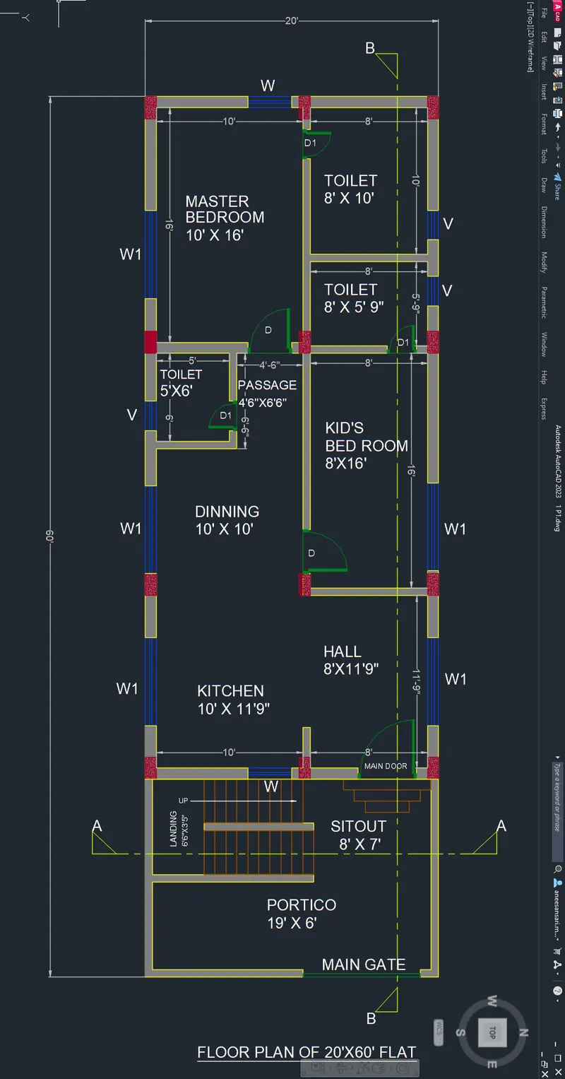
STEP1: Floor Plan:
- First by using the line command draw the outer border of the wall.
- Outer wall =9"
- Inner wall =6"
- Give the solid hatch inside the walls.
- provide doors and windows by changing the layers respectively
- Dimensions are assumed.
- And then provide the column in column layer at required places
- Column= 9"x18"
- Draw the stairs with a thread of 9"
- After that provide the texts at the required locations by using single-line text command.
- Provide dimensions as inner wards and outwards.
- Break dimensions at required locations.
- Every element will be in a unique layer.
- Provide section line at required locations.
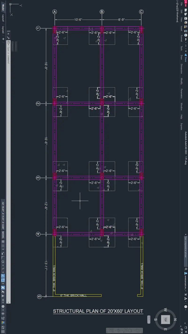
STEP 2: STRUCTURAL LAYOUT:
- In this plan, we are going to provide detailed information about footing, column, beam and walls
- For,
- beams pink colour
- column red
- footing grey
- walls yellow colour has chosen.
- While coming to dimensions:
- beam thk.9" and depth 15"
- column = 9"x 18"
- Footing will be 2'6" offset from every column
- The brick wall is 6" thick.
- These every element are layered separately
- This layout is drawn using xline projectors from the floor plan.
- dimensions, annotations and texts are provided at the required places.
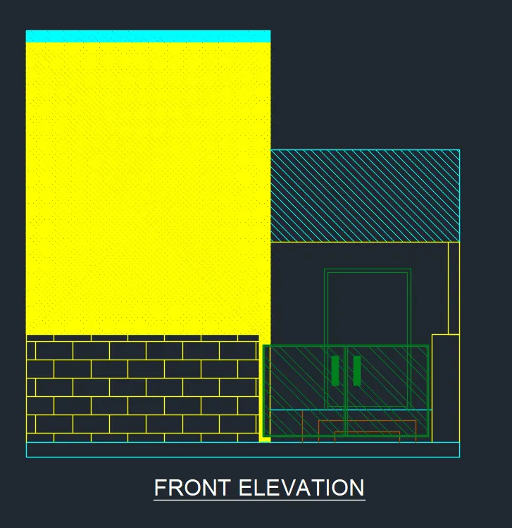
STEP3: Elevation :
- Since we do not have any desired elevation we can just draw in it a simple way.
- Draw vertical projectors using x line from the floor plan
- Draw the floor and slab,
- Draw the elevation of floor height 11' and stairs room height 9'.
- Draw portico stairs of riser 6"
- And provide the main gate to the elevation plan of a high 4.5'
- The compound wall height is 5'.
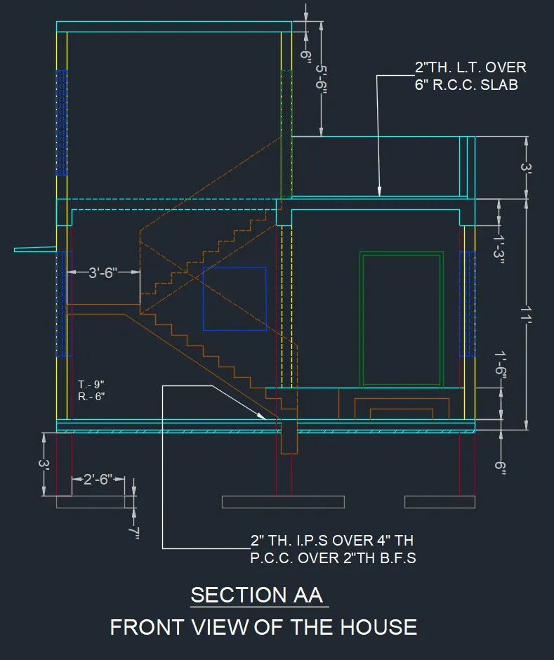
STEP4: SECTION AA :
- Draw the projector lines from the floor plan and start drawing Section AA.
- For the Indication have provided dashed lines for elements and entities which are behind the walls of the section line.
- The staircase is the most important element of the section:
- thread= 9"
- riser= 6"
- Footings are provided accordingly at the bottom of the section
- Footing hight = 6" and offset from column= 2.5'
- foundation column= 9"x18"
- Beam thickness= 9"
- Doors and windows are provided at the required locations in desired dimensions
- After that annotations, dimensions and texts are provided.
- Details of the slab and floor are indicated using LEADERS.
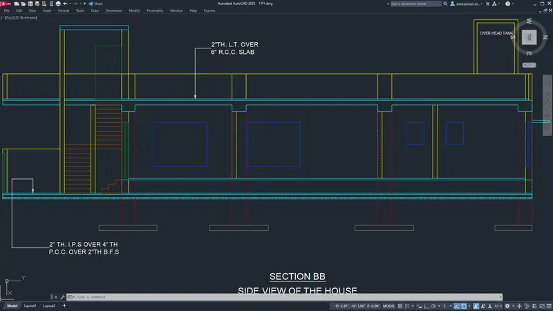
STEP5: SECTION BB :
- Draw the projector lines from the floor plan and rotate them at 90° to intersect the projectors of section AA and start drawing Section BB.
- For the Indication have provided dashed lines for elements and entities which are behind the walls of the section line.
- The staircase is the most important element of the section:
- thread= 9"
- riser= 6"
- Footings are provided accordingly at the bottom of the section
- Footing hight = 6" and offset from column= 2.5'
- foundation column= 9"x18"
- The beam width is 18"
- Doors and windows are provided at the required locations in desired dimensions
- After that annotations, dimensions and texts are provided.
- Details of the slab and floor are indicated using LEADERS.
After completion of that delete the XLINE for a better view.
RESULT:
The floor layout, structural plan, Front Elevation, and sections AA and BB are ready now.