Modelling of 25 storey building with the specified properties using ETABS
AIM: To model a 25-storey building on ETABS with specified structural properties.
OBJECTIVES:
- To know the modelling of a high-rise building in ETABS software.
- To verify the seismic code requirements from ETABS analysis.
INTRODUCTION: To design the 25-storey building on ETABS required data is given below:
Ground floor or plinth floor level can be taken at a height of 1.5 metres from the base. Each of the successive 25 storeys has a storey height of 3 metres.
Structural Element size:
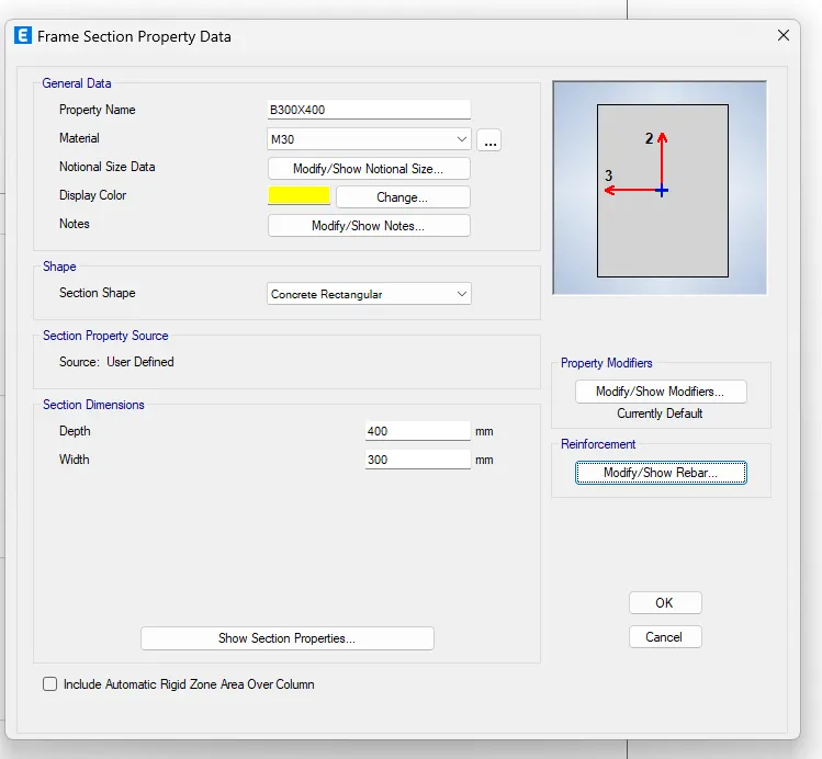
- Beam: 300 X 400 mm
- Columns: 800 X 800 mm
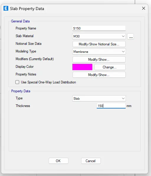
- Slab: 150 mm thick
Material Properties:
- Grade of concrete: M30
- Grade of steel Reinforcement Bars: Fe 415
Loading
- Dead Load on beams from infill wall: 10 kN/m (Let us assume the same for the roof floor in view of the parapet)
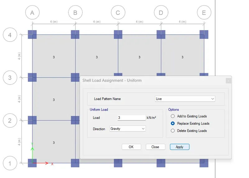
- Live load on the floor : 3 kN/m2 (Let us assume the same for the roof floor)
a) Buildings are assumed to be pinned at the base
b) All columns in all storeys are of the same size
c) All beams in all storeys are of the same size
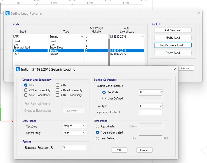
d) Building is located on Soil type II and in Zone III. Assume other factors if required.
PROCEDURE:
Open ETABS software:
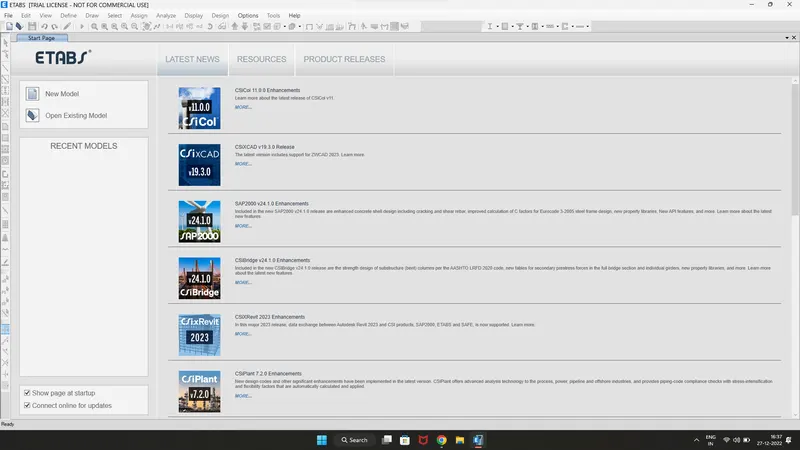
Select New model
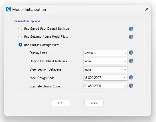
Give model information:
- Use built-in settings with:
- Metric SI
- Indian
- Indian
- IS 800:2007
- IS 456:2000
Then set the template as required:
- Provide gride and storey data:
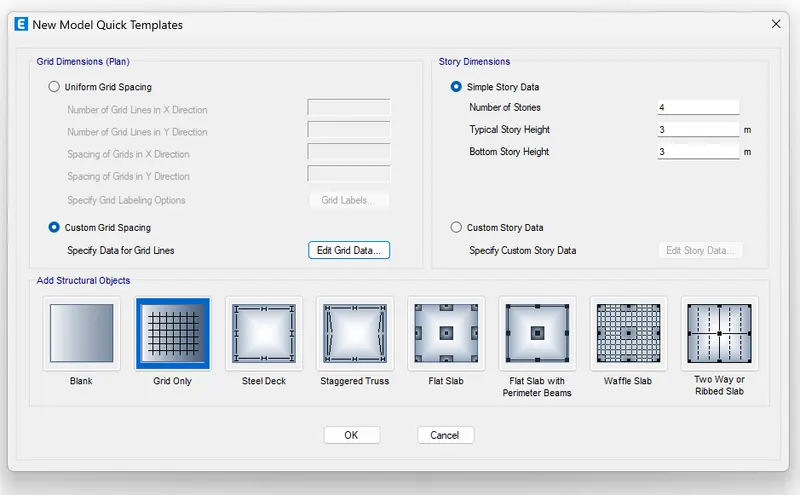
- Grid data:
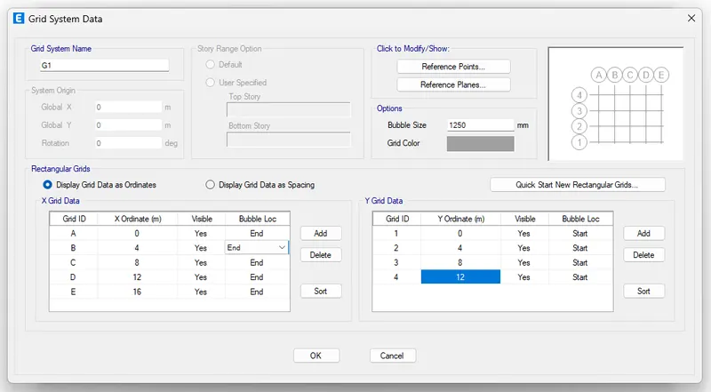
- Storey data:
- Add additional storeys:
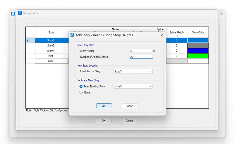
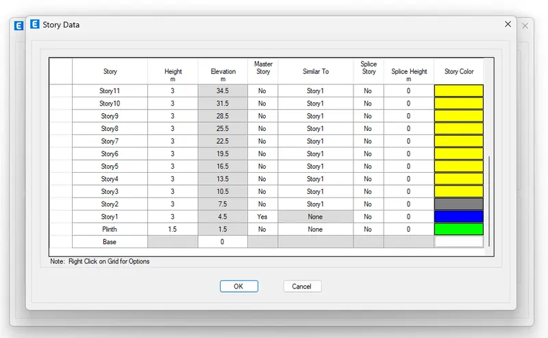
- Add additional storeys:
- Grid data:
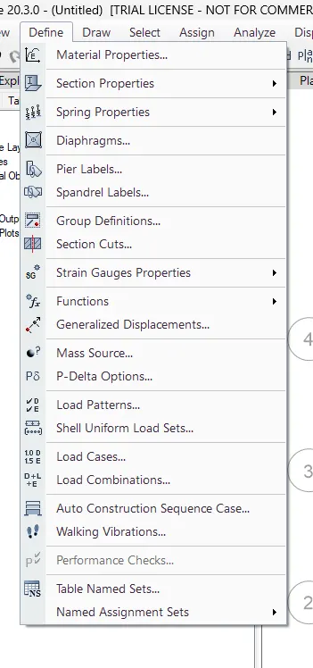
Provide materials for the project. 'Define<material property<add new material'.
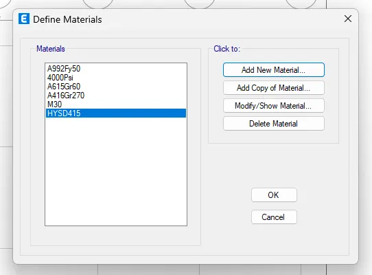
Go to section properties in define and create a new frame section:
- give desired reinforcement details and dimensions for beams, and columns.
Go to define and define slab sections
And go for load patterns in define and add new loads (brick wall loads, seismic loads, eccentric loads)
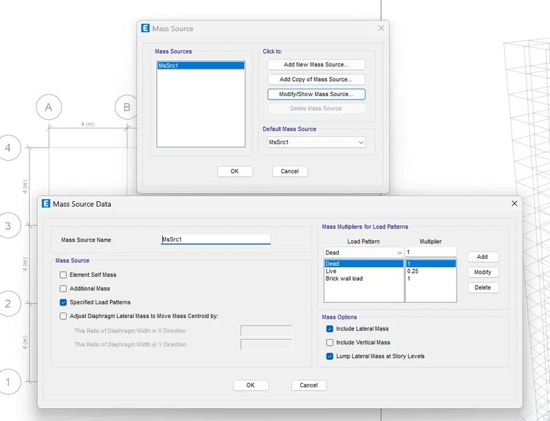
Add mass source data
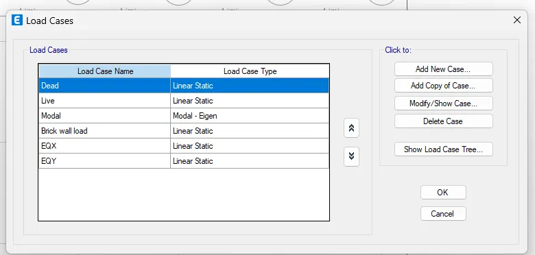
Edit load cases:
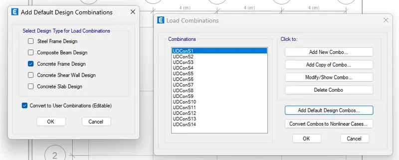
Define load combinations:
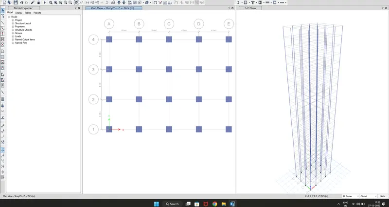
Now it's a modelling state:
Add columns and beams to the respective storeys:
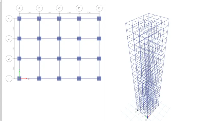
Now its time to model the slab:
Go to story 1, change the type to similar storeys and design the slab there:
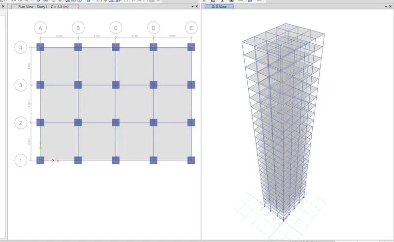
In default, supports are pinned supports.
The modelling part is done now.
We have to assign loads now.
Go to select and select every beam to assign brick wall load.
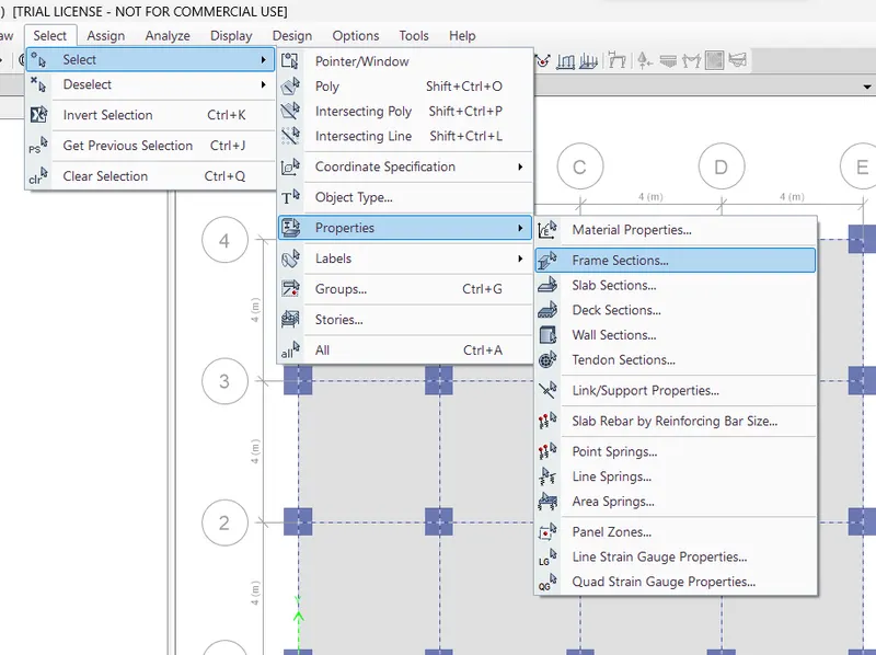
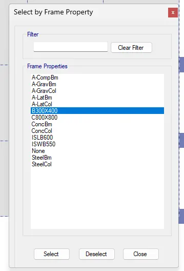
Assign loads from assign option
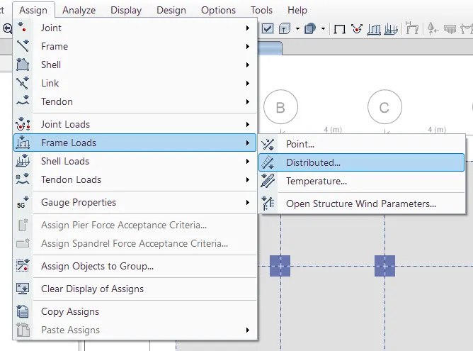
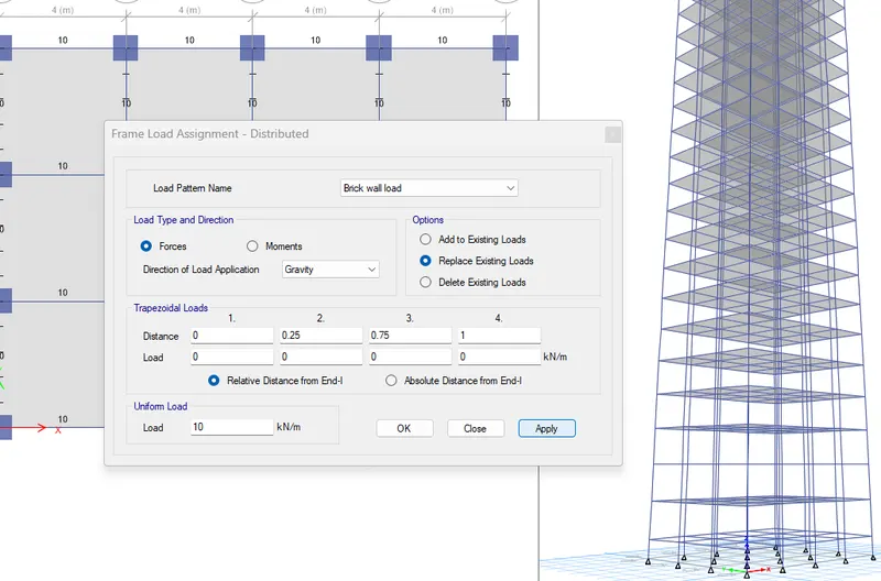
In the same way assign the slabs loads:
Select slabs again to assign diaphragms
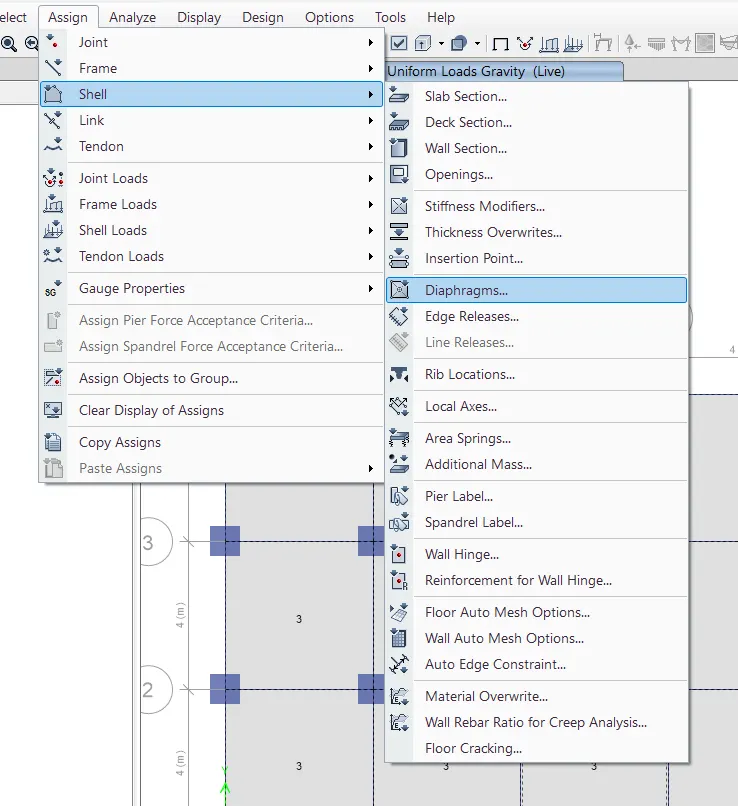
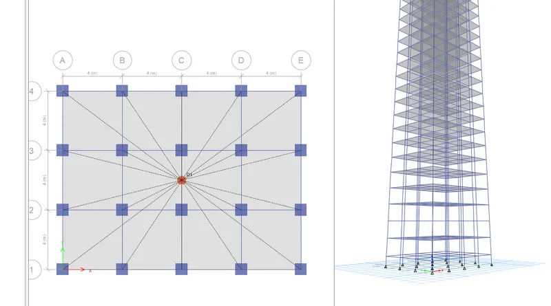
These diaphragms are very much helpful to calculate the lateral load calculations.
Now analyse the model by saving it.
Click the F5 button to analyse the model.
It is 25 storey building, so it takes some time to analyse it.
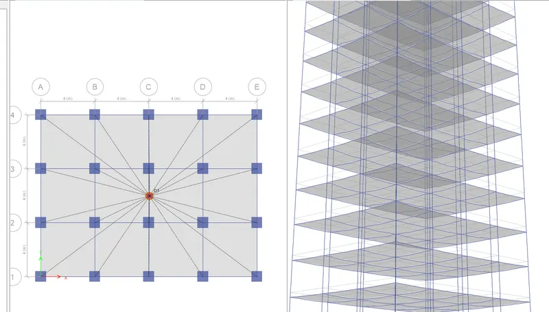
The analysis is done and we can see the deflections in the 3D model.
Now we have to check for the questions asked in the challenge.
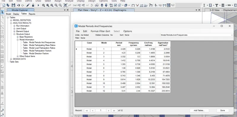
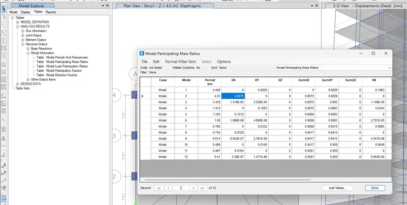
Go to the respective tables to check the results:
RESULT:
| Criteria | Desirable Solution | Exercise result | |
| The translational fundamental natural period | X-direction | 4.4 seconds | 4.43 |
| Y-direction | 4.2 seconds | 4.23 | |
| Torsional irregularity | IS 1893-2016(Part-1) table-5 | The torsional mode Time period should be lesser than the X and Y direction time periods | Yes |
| Vertical irregularity | IS 1893-2016(Part-1) table-6 clause-7 | The first three modes together should contribute at least 65% of the mass participation factor in each principal direction. | Yes |
| Fundamental lateral natural periods in two principal plane directions are away from each other by at least 10% | No. | ||
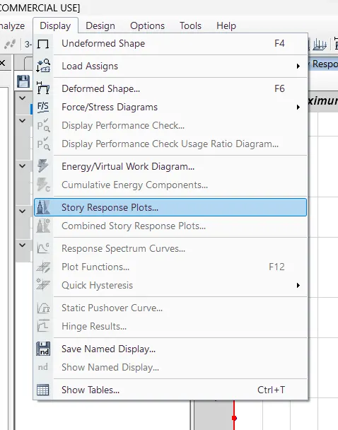
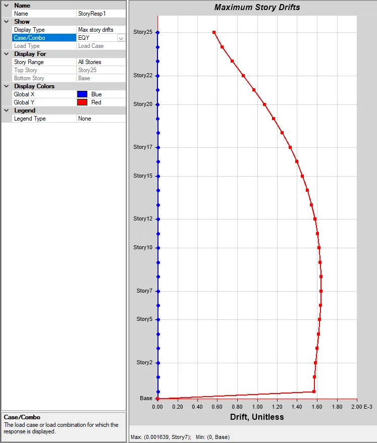
| Inter-storey Drift | IS 1893-2016(Part-1) clause-7.11.1.1 | Storey drift shall not exceed 0.005 times the storey height for base shear with no load factors (4x10^-3) | Yes, We have achived it . It is not exceeding 1.5-1.6E-3 |