Creating Conceptual mass in REVIT and Creation of Sinusoidal curve and a Parametric stadium using Dynamo
1) Using Dynamo create a set of sinusoidal points and create a curve and create a surface out of the curve.
Ans:
AIM: To create a set of sinusoidal points and create a curve and surface out of the curve in DYNAMO.
INTRODUCTION: Dynamo is a visual programming tool of REVIT, which is used to create Parametric structures in REVIT.
We can find Dynamo in the Manage Tab of REVIT.
PROCEDURE:
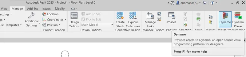
Initially open the Revit window and go to the manage tab, In the right side top corner we can fine DYNAMO.
Open it to access DYNAMO.
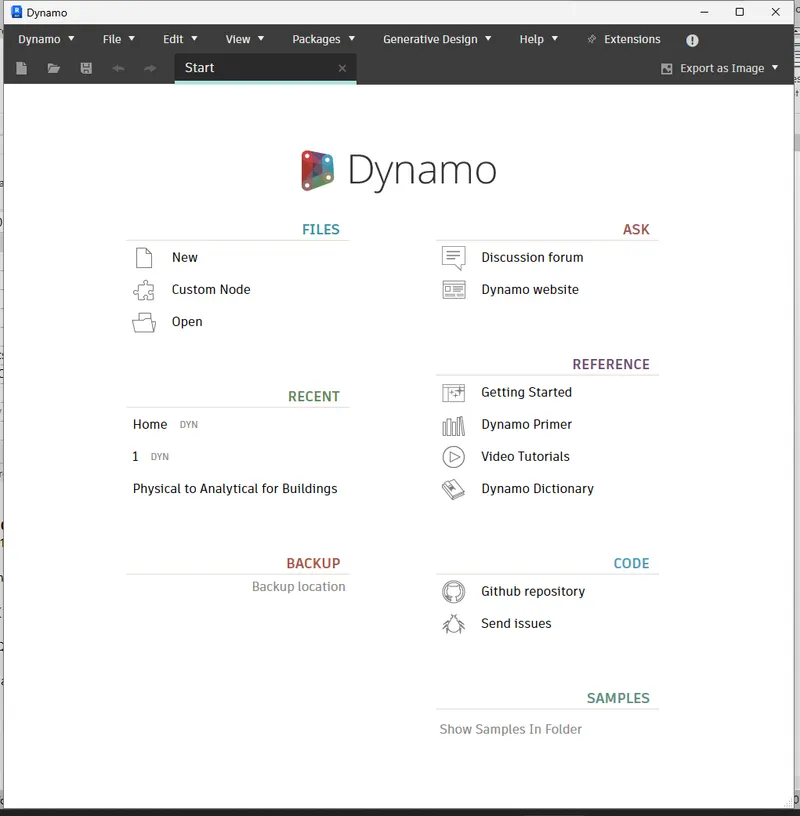
Open NEW file.
In the new file, We can find the LIBRARY tab on the left of the window.
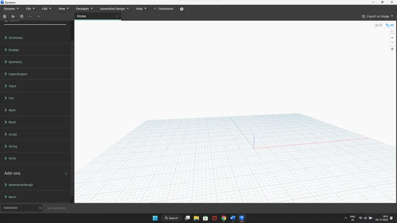
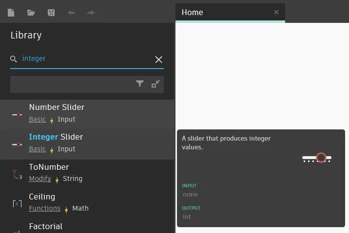
Open the Number slider to create a number.
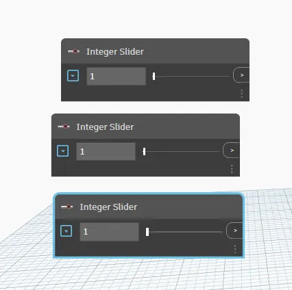
Use Ctrl+C and Ctrl+V to copy and paste the slider.
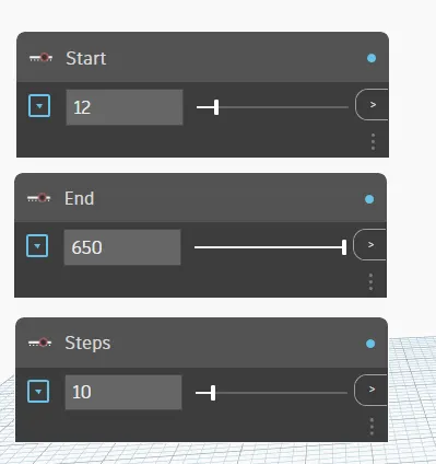
Rename the sliders and set limits to them.
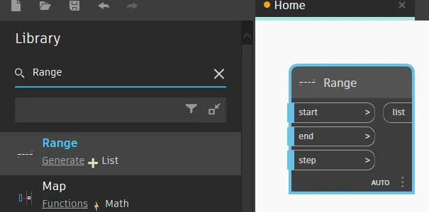
Open range to specify the range of the points:
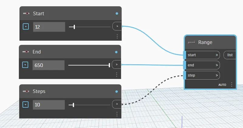
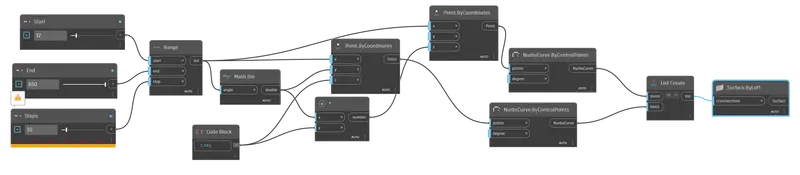
Connect the range and sliders as shown below:
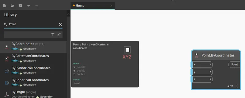
To specify the point open POINT.BYCOORDINATES
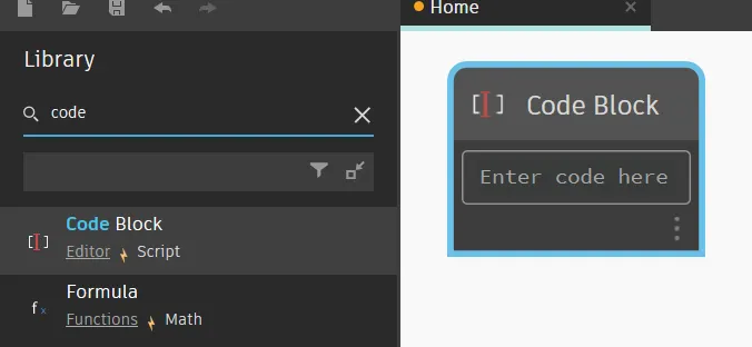
Open code block to denote a code:
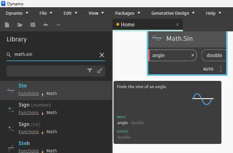
To provide a curve in the model, open Math.Sin:
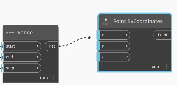
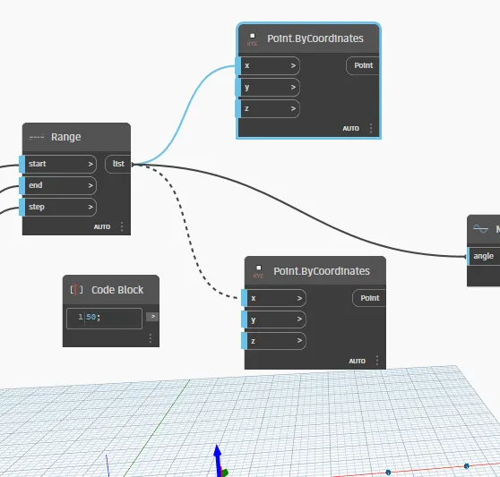
Connect Range and Point.ByCoordinates as shown below:
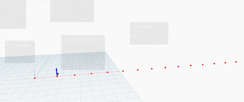
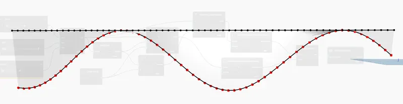
Nodes will be formed as defined:
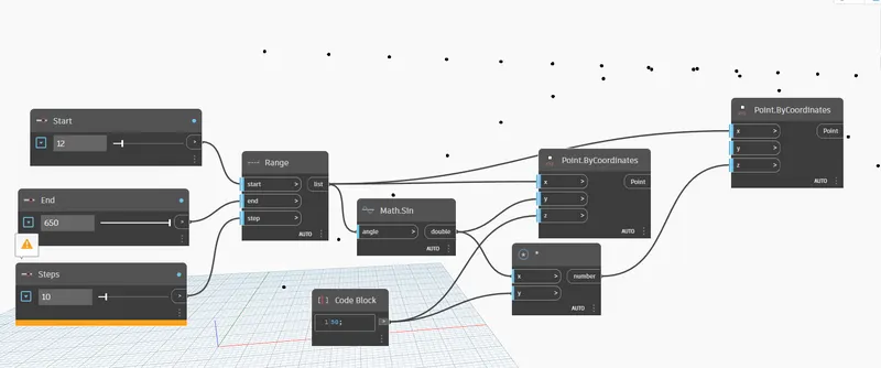
Provide the number in the Code block as 50, and connect the Range to math sin and second Point.Bycoordinates:
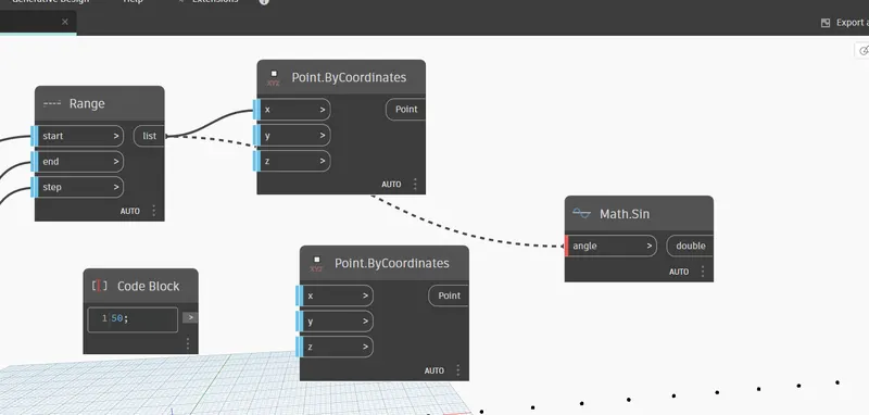
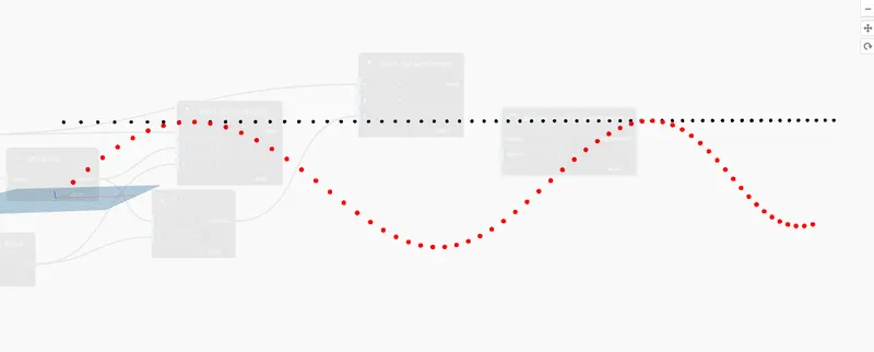
The curve of the Dotes and Line of dotes will be formed.
Open NurbsCurve.ByControlPoints to connect the dots in curve:
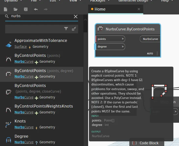
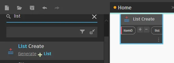
Open List Create to create the list:
Connect them as shown below:
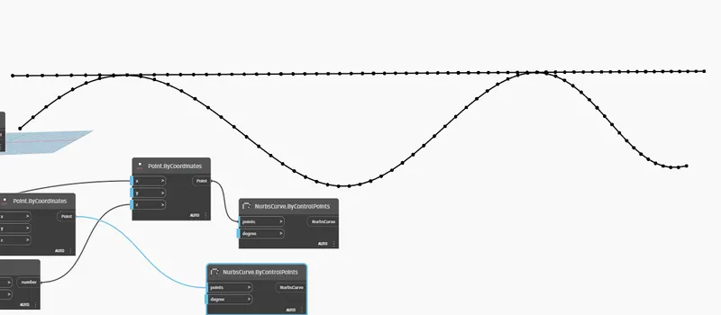
A line and a curve are formed.
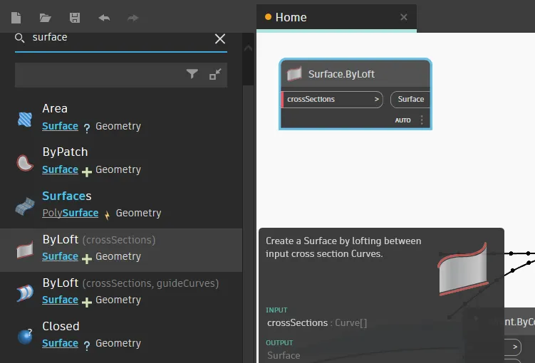
Then open the surface. ByLoft to create a surface from the curves
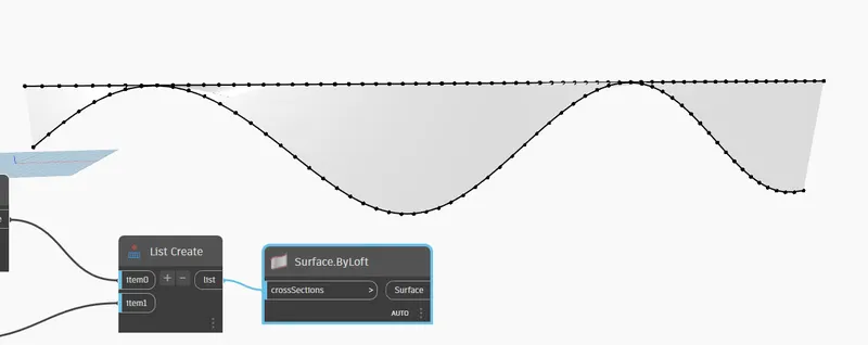
RESULT:
This is the Programme to create the sinusoidal Curve and surface from it:
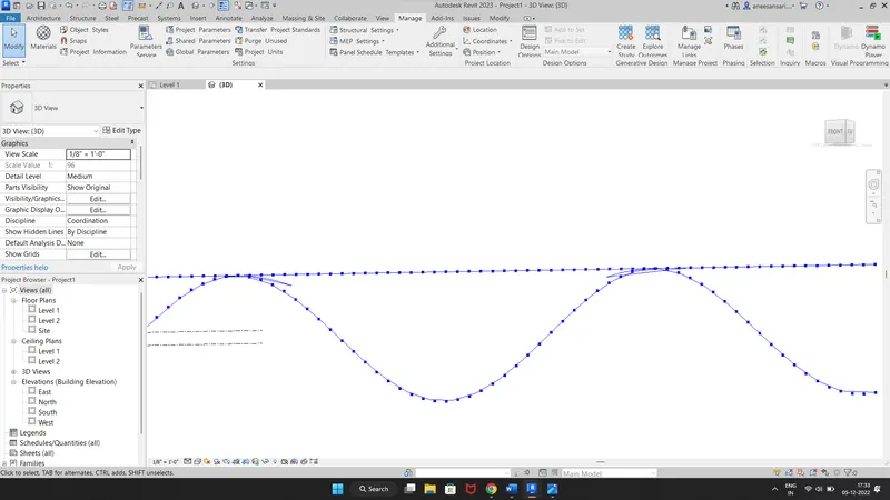
Open Revit screen in the background, We can see it is also formed in Revit:
2) Create a conceptual layout of floor plan in dynamo. Using the tools available in dynamo link the lines to appropriate model elements in Revit by choosing the wall types and wall parameters. Make use of the sliders to slide through the height of the wall and the length of the wall.
Ans:
AIM: To create the conceptual layout of the floor and walls in Revit using DYNAMO.
INTRODUCTION: F In DYNAMO is mainly used to create parametric structures. It can be done for buildings, things and many objects. In this project, we are going to create a conceptual layout out of the floor plan in dynamo and using the tools available in dynamo link the lines to appropriate model elements in Revit by choosing the wall types and wall parameters. And to make use of the sliders to slide through the height of the wall and length of the wall.
PROCEDURE:
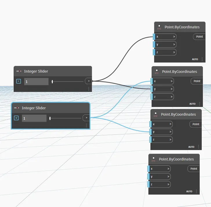
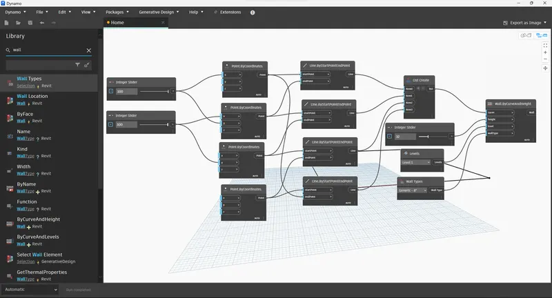
Go to DYNAMO in the new file of Revit, and open two integer sliders.
For drawing the wall open the 4 points by Coordinates.
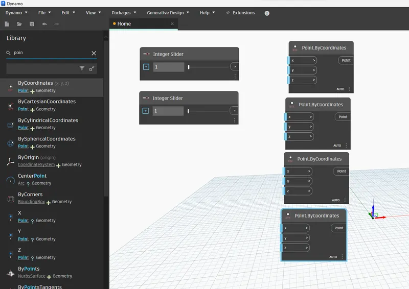
Connect them as shown below to make the corners of the layout:
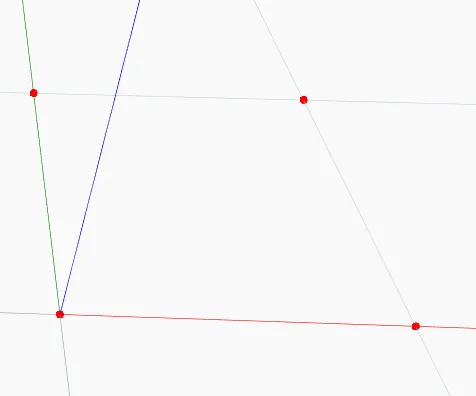
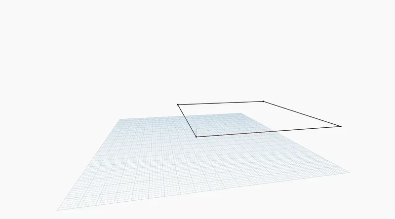
We can see that Points are made in the background:
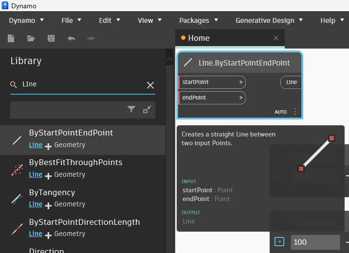
An open line to connect the nodes:
Connect them as shown in figure:
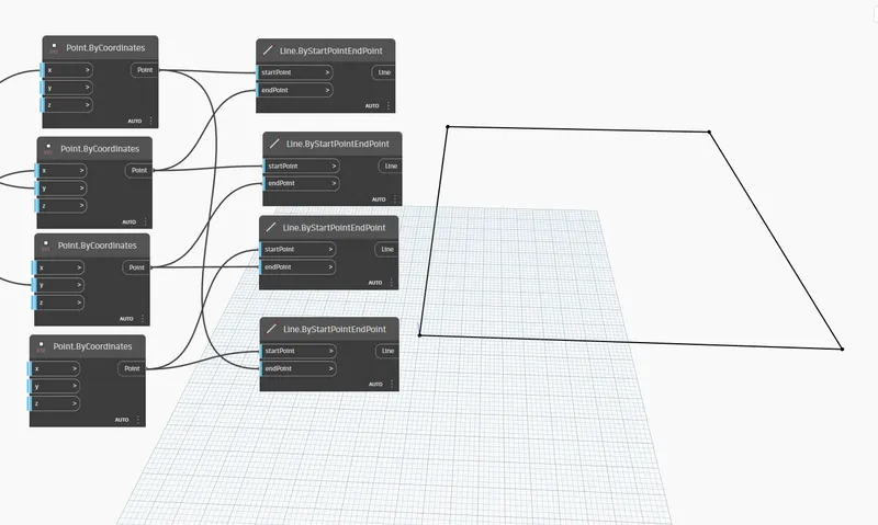
Open the list create option and connect the lines to the list to create the walls
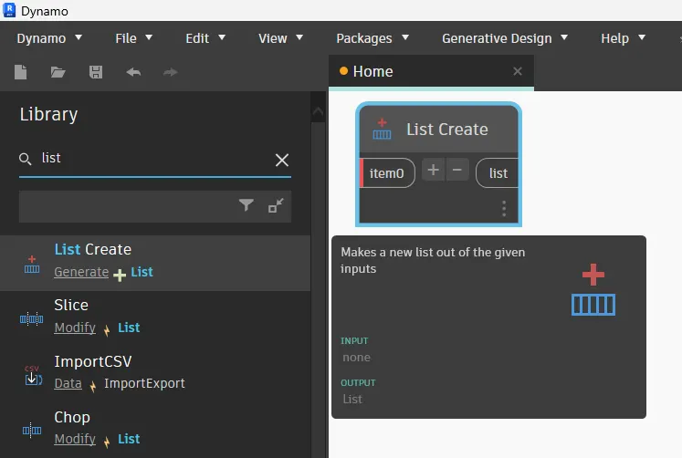
open levels
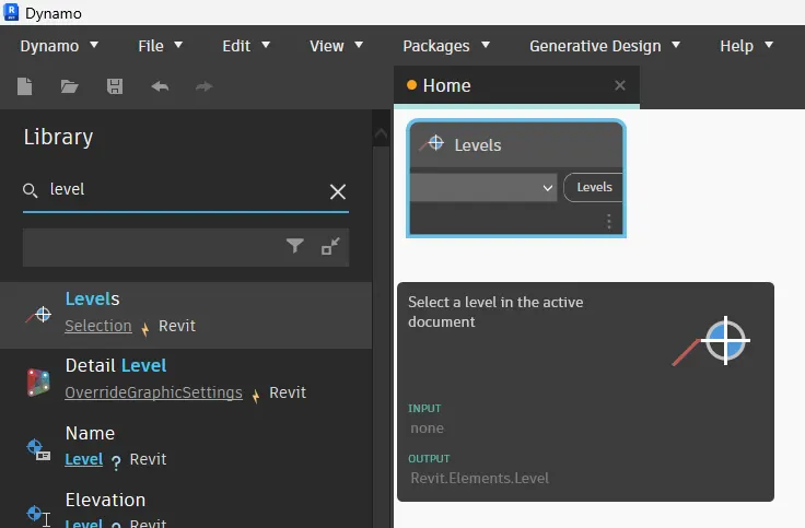
Open wall types to define the type of wall:
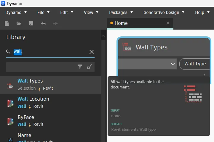
Open Wall.Bycruveandheight to build the wall:
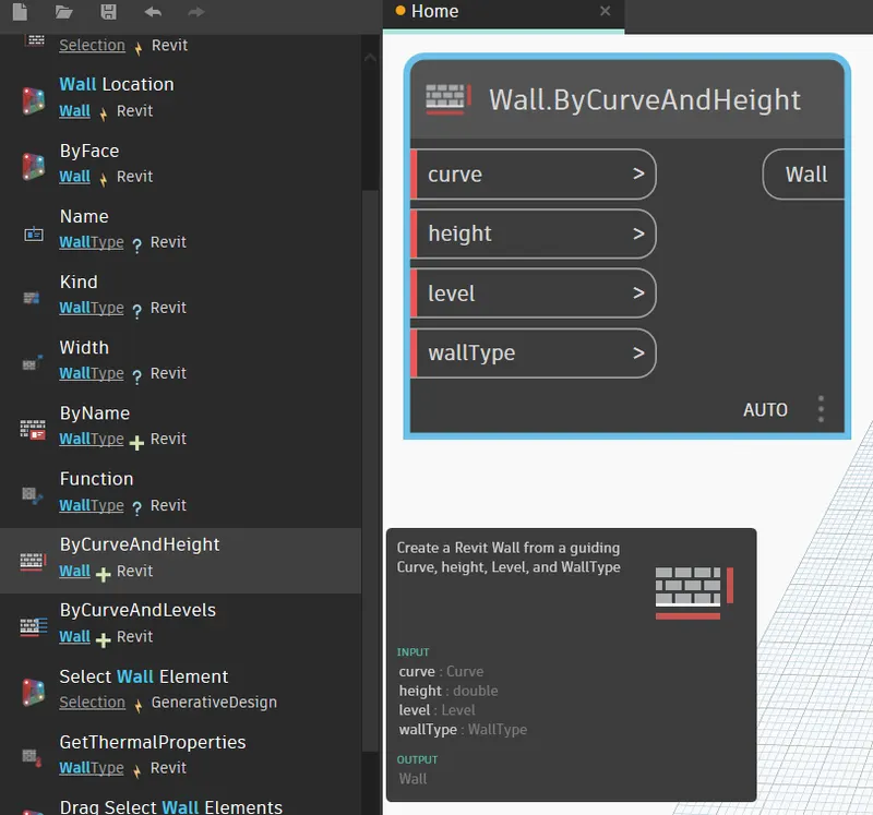
And connect them as shown below:
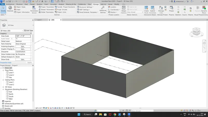
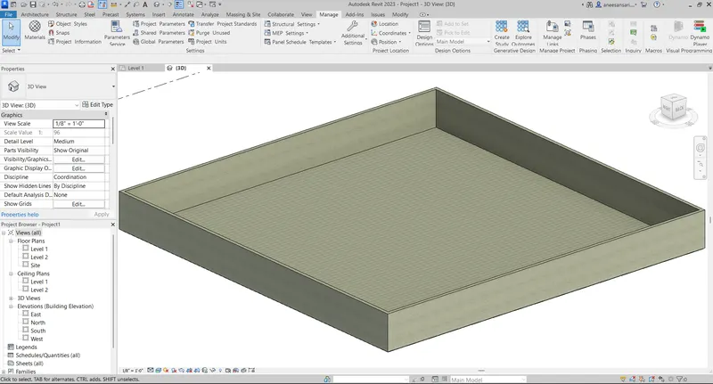
On Revit window, we can see the wall :
Now we should create the floor using dynamo:
Open floor Type and floor by outline curve:
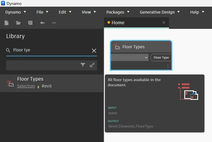
Open Floor types to define the type of floors
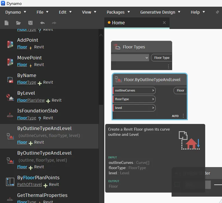
Choose floor type and connect them as shown in the figure:
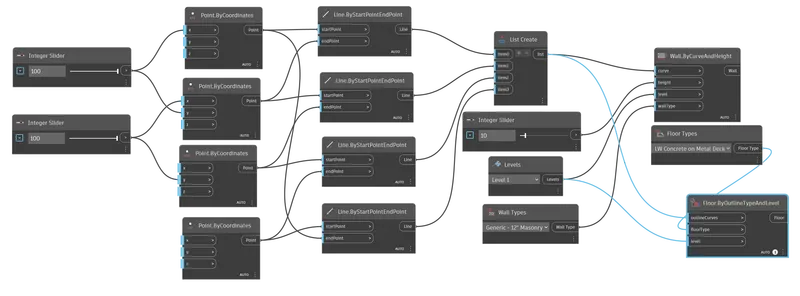
And this is the background 3D view:
RESULT:
Open the Revit file in 3d view to view the output result:
3) Create an array of model elements in Revit. Use dynamo to vary the properties of model elements by using the slider or code block
Ans:
AIM: To create an array of model elements in Revit and to vary the properties of model elements by using the slider or code block in DYNAMO.
INTRODUCTION: Dynamo is a visual programming tool of REVIT. We can modify the model in DYNAMO which we have designed in the Revit window.
That is the objective of this project.
PROCEDURE:
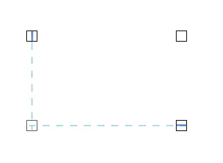
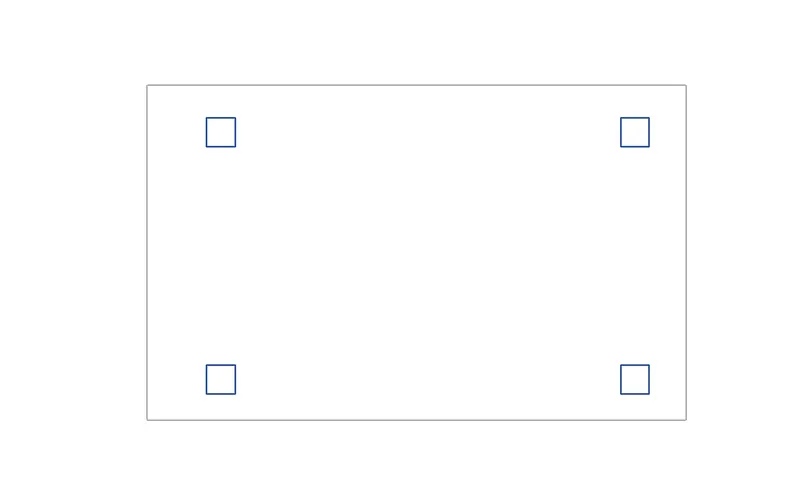
Open the Revit project initially, provide any one component and place it on the screen. I have provided an Architectural column.
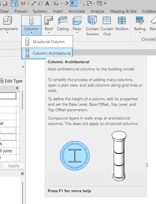
Provide 4 columns as shown below:
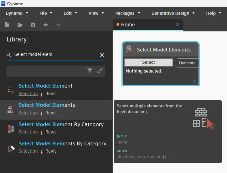
Now open dynamo and close select model element( multiple ) Option to select elements in architectural model:
We need to rotate that column to 45 degrees. So insert the set-by-rotation option in the dynamo window
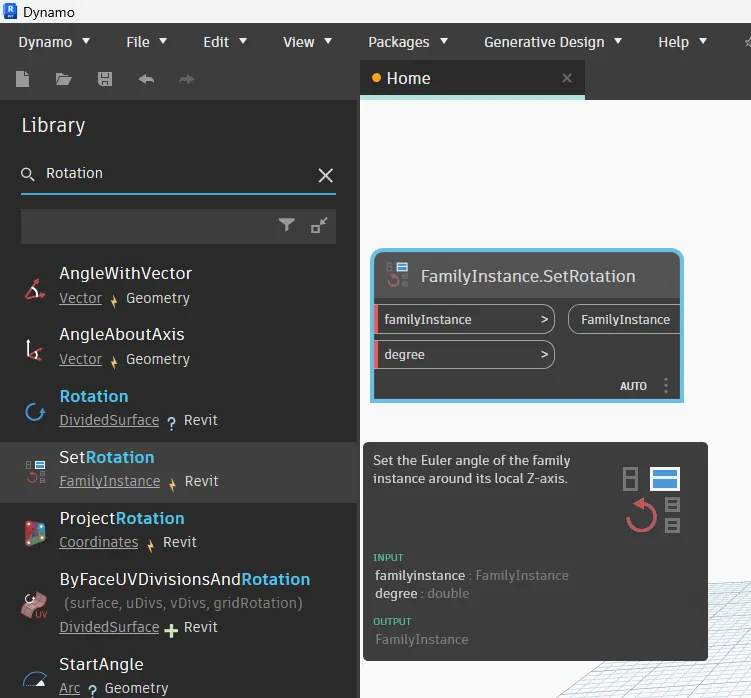
And open the integer slider to provide a rotation angle to the column:
Now there is nothing selected in the Select model element tab.
We have to click the select option:
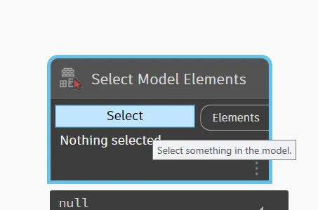
then Go to revit screen and select four columns:
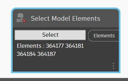
And now those 4 columns are been selected in dynamo:
Rename the integer slider as a rotational angle and give the angle as 45 degrees.
Now connect all blocks as shown below:
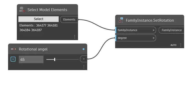
RESULT:
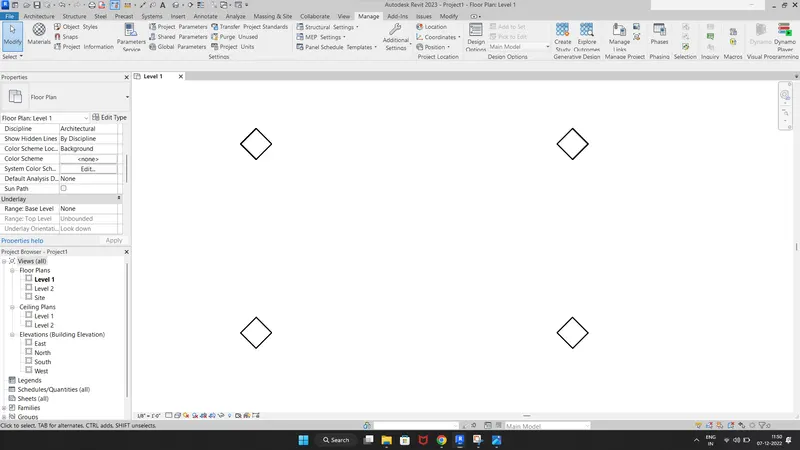
All 4 columns are been rotated at 45 degrees in the Revit screen:
4) Create a conceptual mass in Revit and develop a parametric column by dividing the surfaces and apply the concepts similar to used in parametric walkway modelling. Use triangular bent or square shaped panels to add finish to the parametric column
Ans:
AIM: To create a conceptual mass in Revit and develop a parametric column by dividing the surfaces and applying concepts similar to parametric walkway modelling which has been made in previous lectures and to use triangular bent or square-shaped panels to add a finish to the parametric column.
INTRODUCTION: Up to now we have discussed the design of parametric models using DYNAMO. In this, we are going to make a parametric column using REVIT conceptual mass. We can also define the panelling shapes in REVIT.
PROCEDURE:
Go to the architectural template and then create conceptual mass.
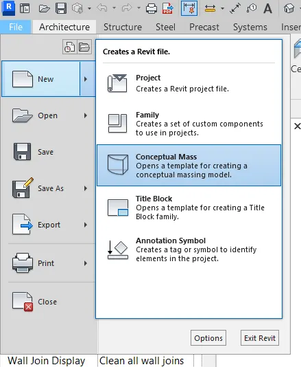
Go to File, click on New and then conceptual mass:
Open Metric Mass template.
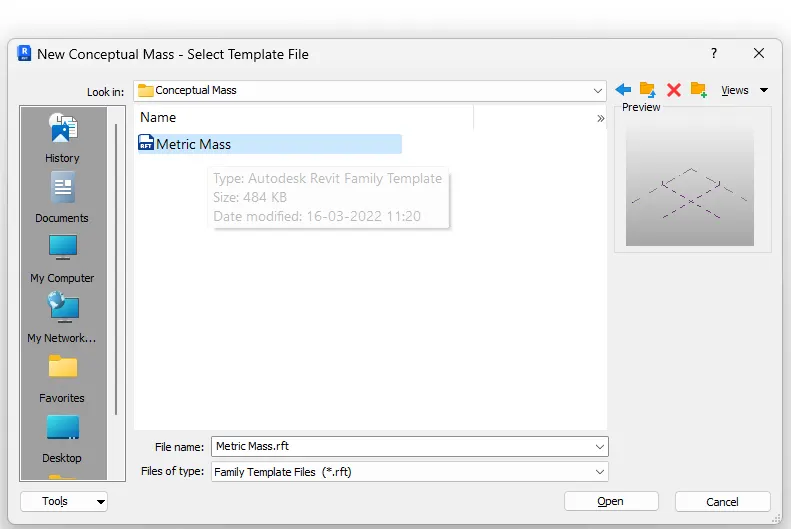
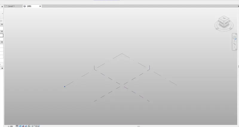
This is the template of metric mass:
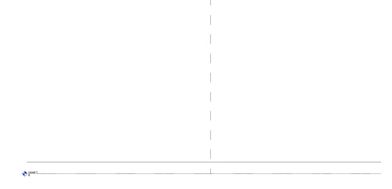
Open the Elevation view and create a new level at 12' from the base level:
Now go to create the spline curve by creating the model lines:
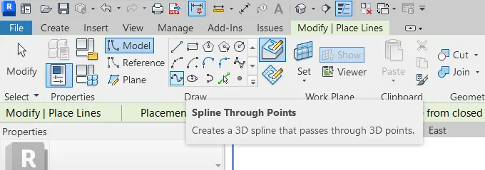
This is now Spline curve is created:
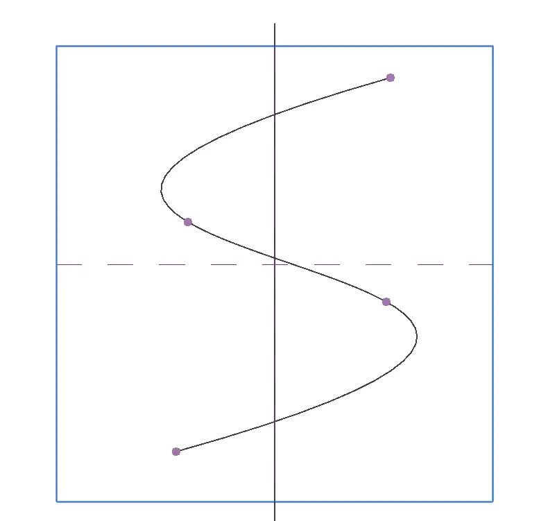
Set the Surfaces at each Nodes of spline curve:
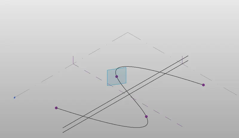
Draw the inscribed polygon with radius of 12' at each node:
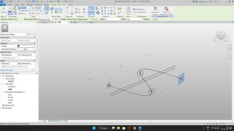
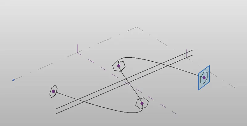
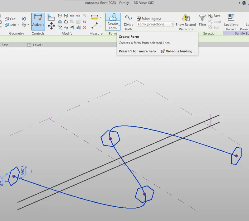
By selecting reference line and polygons , create the form
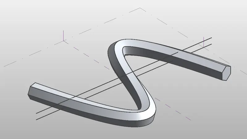
Form is created
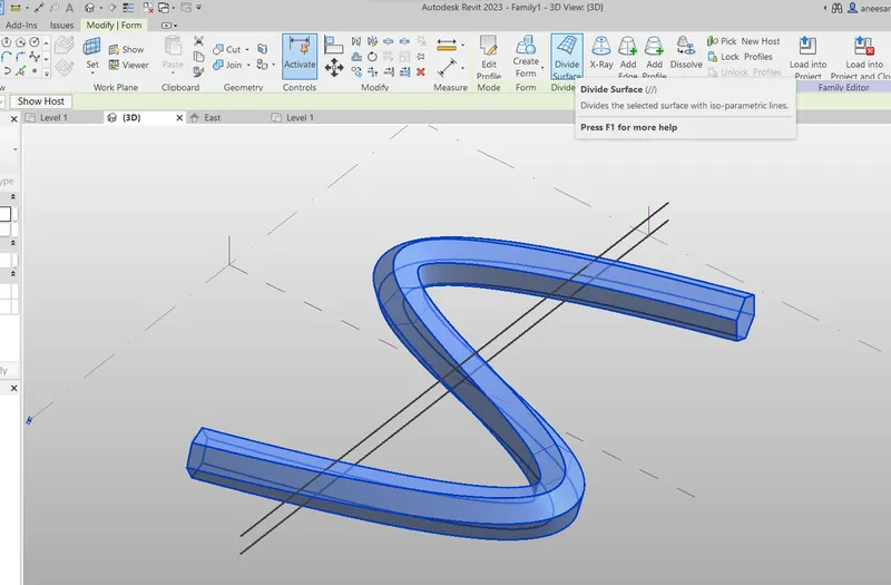
Select the form and divide it as U 100 V 10
Unselect corner surfaces:
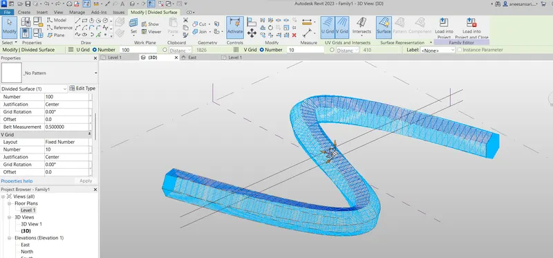
Select divided surfaces and make them as triangle (bent)
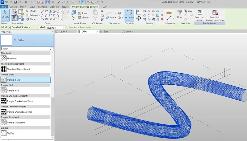
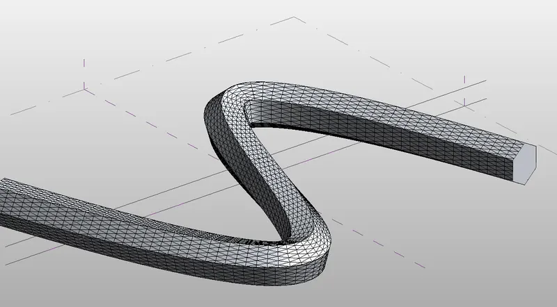
Form is created:
Open new family < metric curtain panel pattern based:
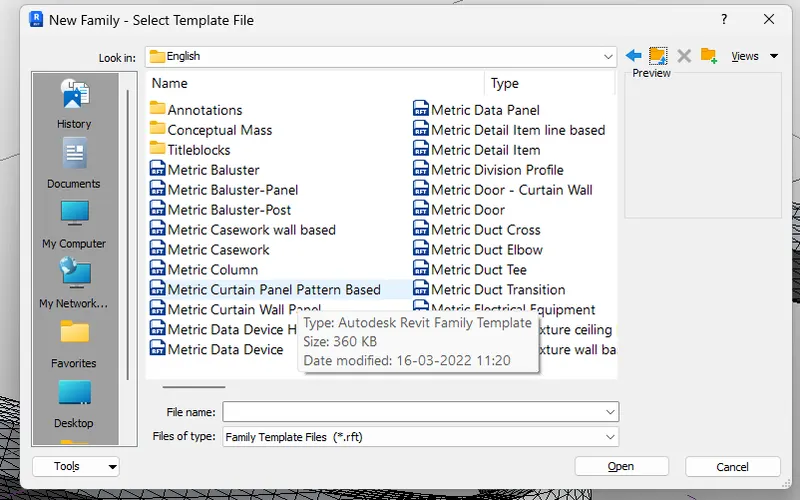
Family template is opened and make it as triangle ( bent ) to match our model:
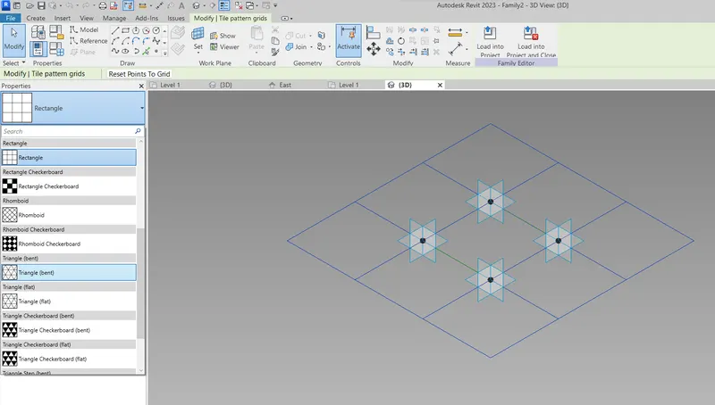
Triangle bent:
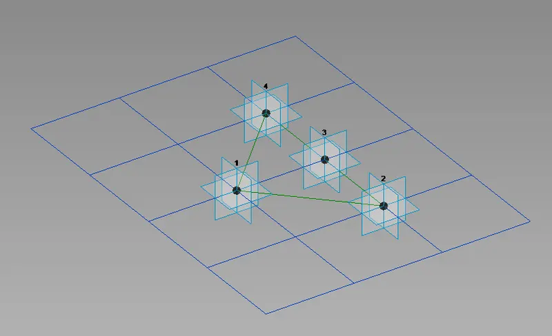
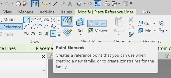
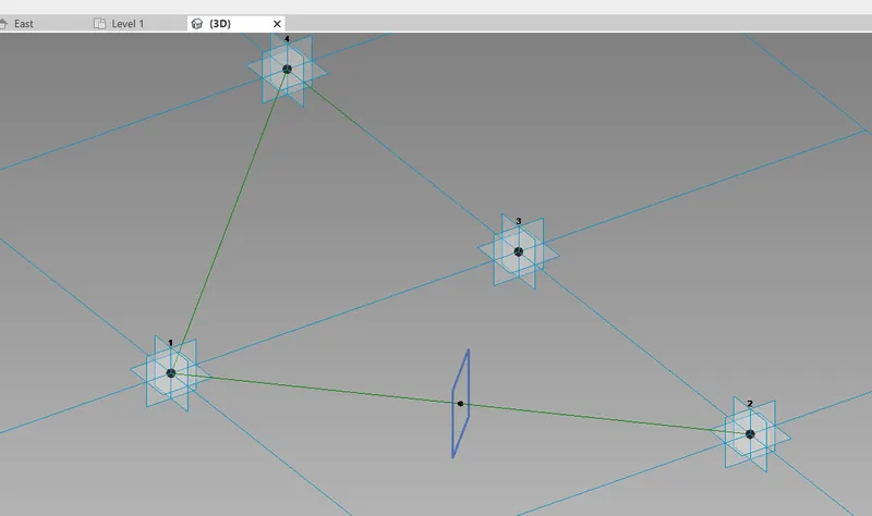
Select reference and create point at centre of any line
Set surface at that point
And create circle at that surface:
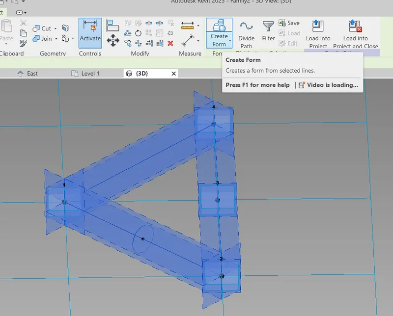
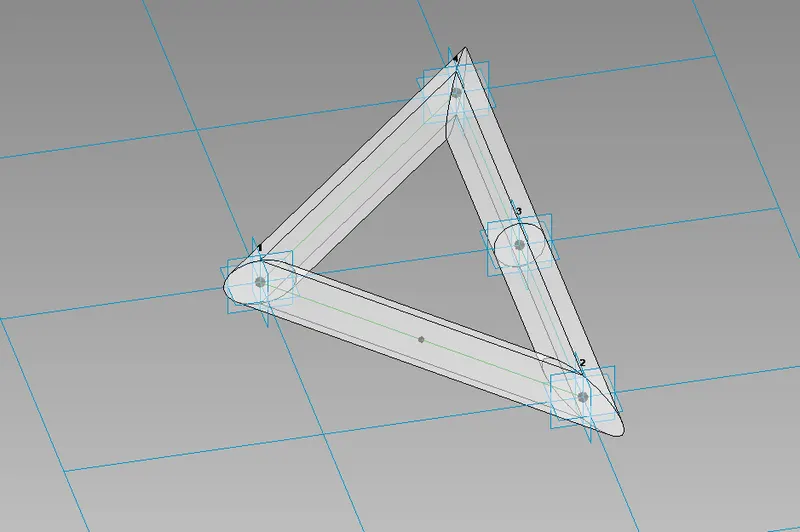
Select family and circles, and make it a form.
We can give material to the form as we wish.
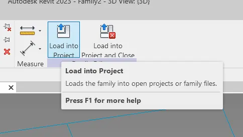
Load it into the project :
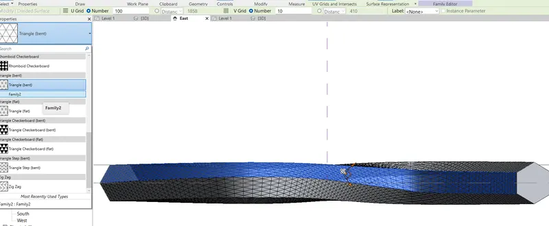
Now, select divided surfaced one by one and change the surface texture to which we have created:
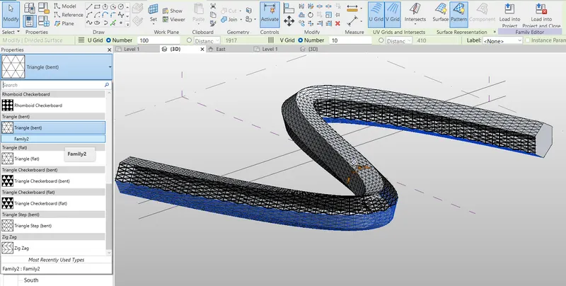
RESULT:
The parametric walk through is finished:
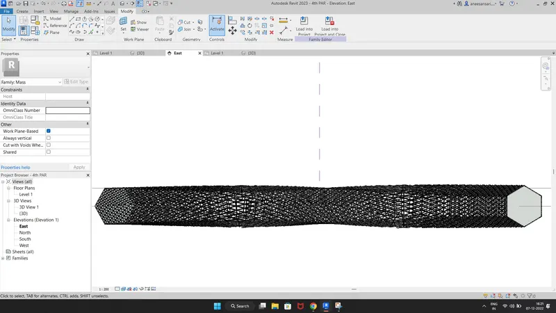
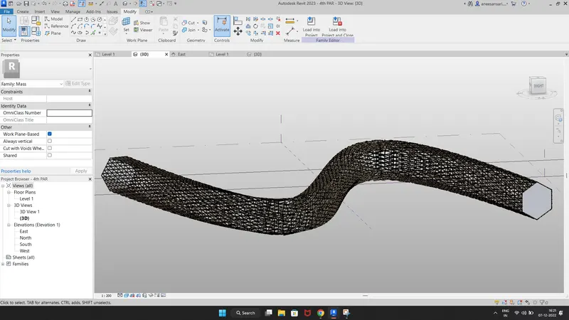
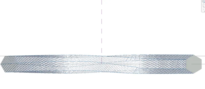
5) Use Dynamo to work on developing a Parametric Stadium. List your parameters and use the visual programming approach to complete the modelling, You can use the concepts discussed in parametric high rise tower in class for reference
Ans:
AIM: To create a Parametric Stadium using DYNAMO and list the parameters and use the visual programming approach to complete the modelling.
INTRODUCTION: Nowadays parametric models are getting into trend and aesthetics. To design that kind of parametric model we need to use visual programming software.
In this project, we are going to use DYNAMO to create a Parametric Stadium.
PROCEDURE:
Open a new dynamo file from the new Rivet file
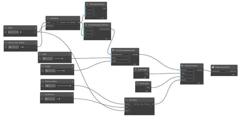
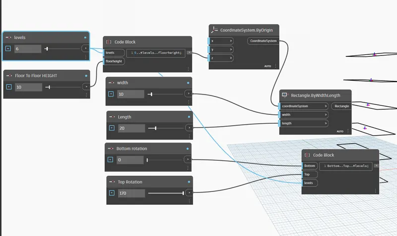
Open two integer sliders and rename them as LEVEL and FLOOR height
Set the level as 5 and the height as 10
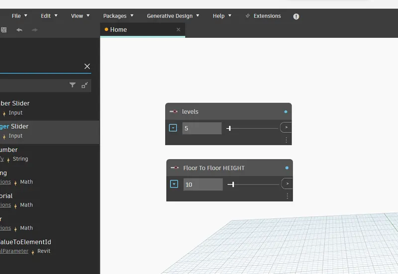
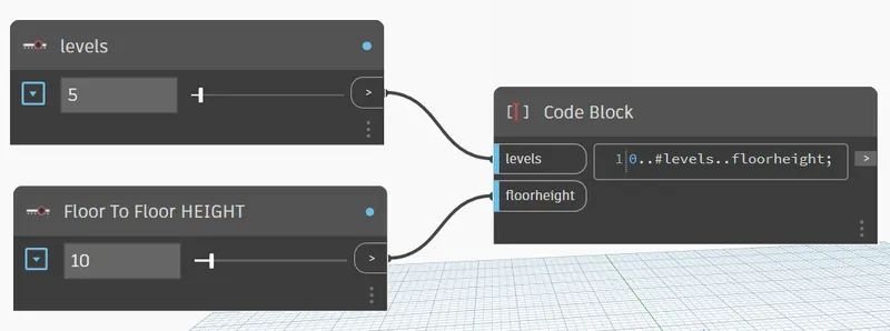
Open code block and manually write code '0..#levels..floor height and connect them as shown below
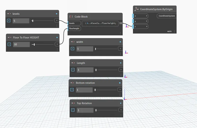
Now, we have to define the width and length of the building.
For that insert the CoordinateSystem.Byorigin and provide 4 integer sliders for width, length, bottom floor rotation and top floor rotation
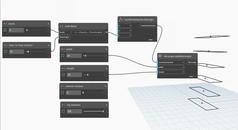
Insert Rectangle.ByWidthLength ( coordinate system )
Connect them as shown below:
Insert code blocks for floor rotation and give code as 'Bottom..Top..#levels' and connect them as shown bellow
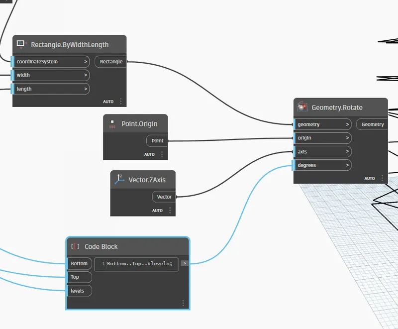
Now we have to connect this code block to geometric rotation.
For that insert origin and vectorZ.axis
Now insert Geometry.Rotate (geometry origin axis degree)
And connect them as below:
Now we have to create the surface:
For that insert polysurface.byloft and connect it to Geometry.Rotate
RESULT:
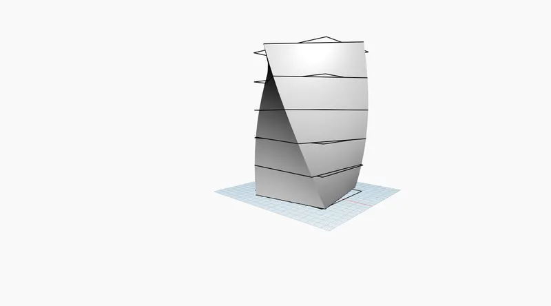
A parametric structure has formed :