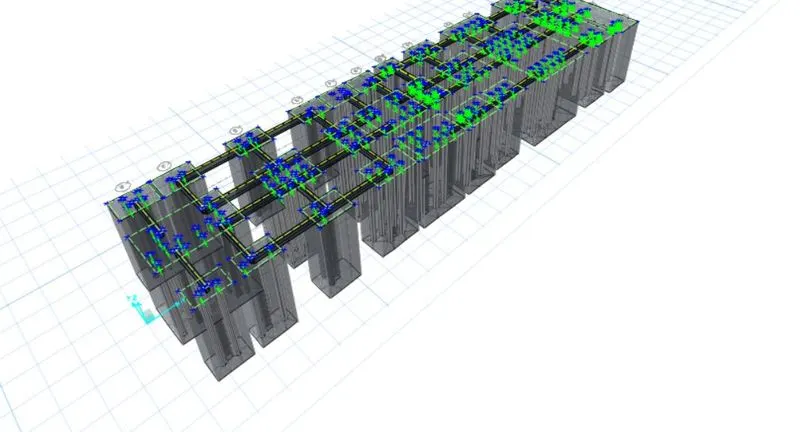
Project 2_Design & Analysis of a Hostel building at Guwahati, Assam
AIM: To Create and Analyse the given building in ETABS and the structural model has to be prepared in accordance with IS 1893 and IS 13920. To design the pile cap and pile reinforcement details, Tie the beam connecting the pile caps, and sketch the column reinforcements, to produce the framing plan and beam detailing for the ground floor.
GIVEN DATA:
- Location – Guwahati, Assam
- Function – Hostel block in an academic institute
- Walls are made of AAC blocks Pile capacity - 280 kN
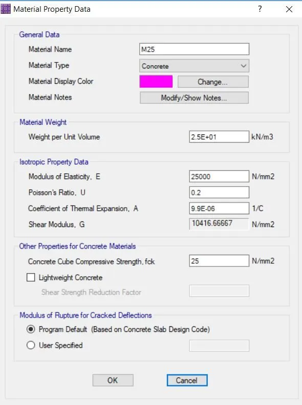
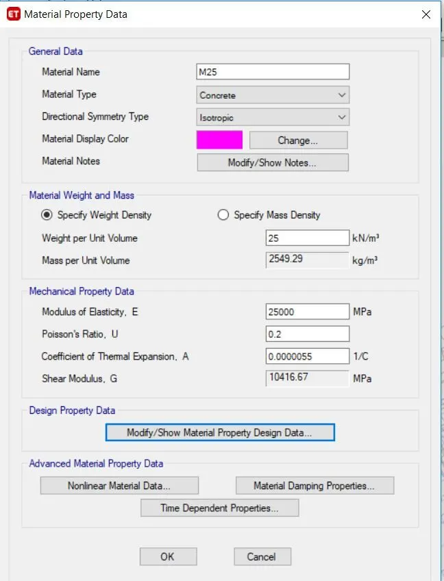
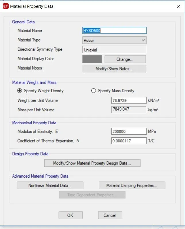
- M25 concrete Fe 500 Steel
- Soil type is 3
INTRODUCTION:
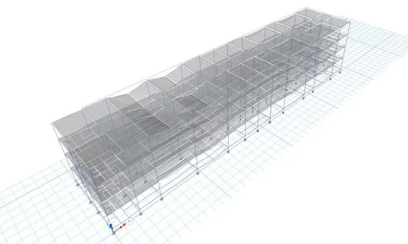
- In ETABS, We can create a structural model of the building with the given Data
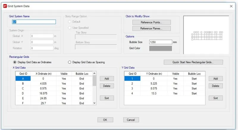
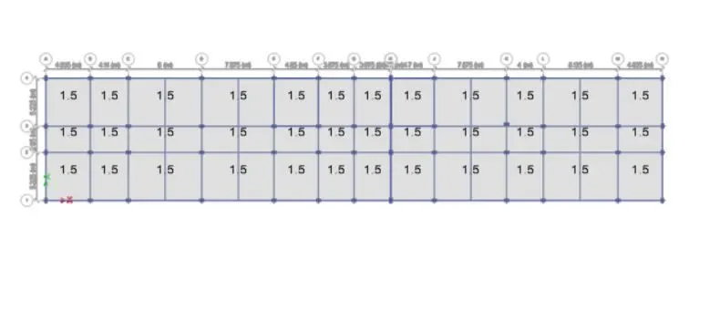
- In this, the first step is to note down the values of grid spacing from the given structural plans.
- After that, we have to create the structural model and run the analysis.
- Analyse the result and note down the result values from ETABS.
- Next is to export the model to SAFE 2016 software in order to design the foundations.
PROCEDURE:
- in the first step open the ETABS software go to the file and click on the new model.
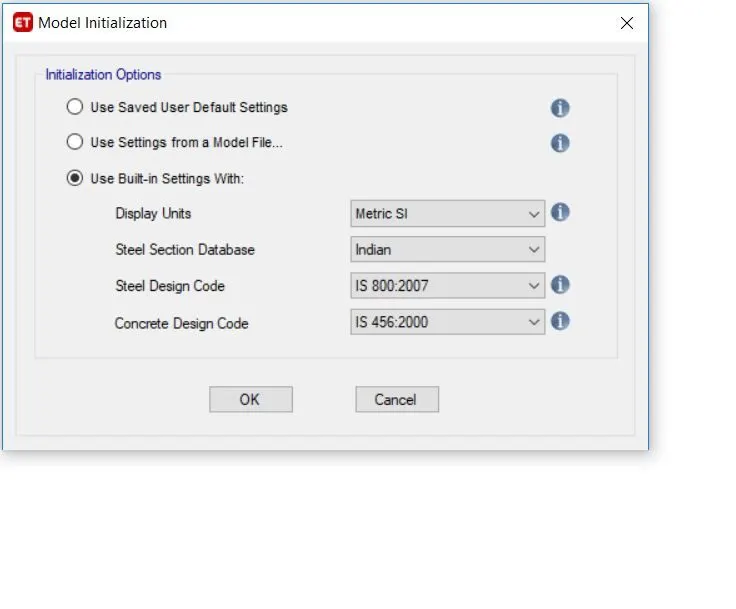
- Model initialisation window will appear.
- Click on the use built-in setting and select the Indian codes and click ok.
- Click on the custom grid data and click ok.
- Now the values as per the given plans are inserted and our model will be ready.
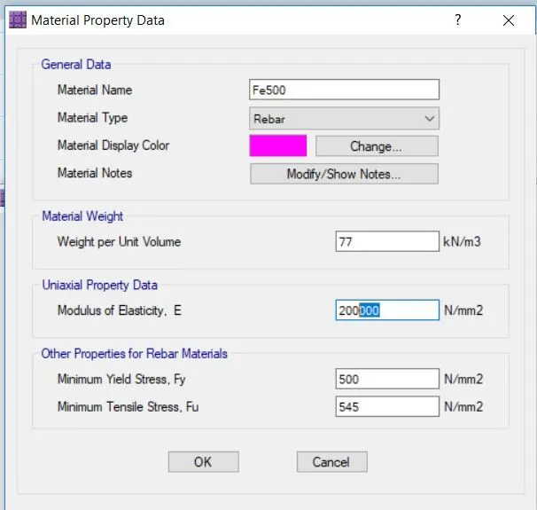
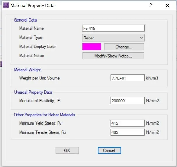
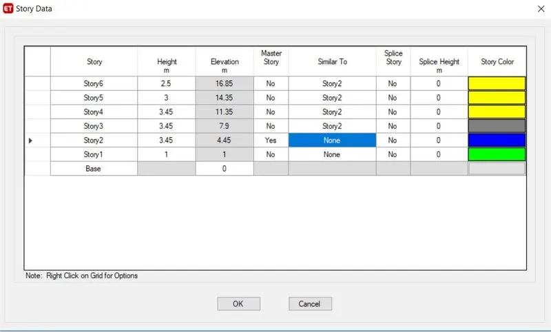
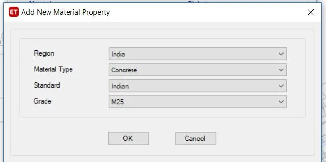
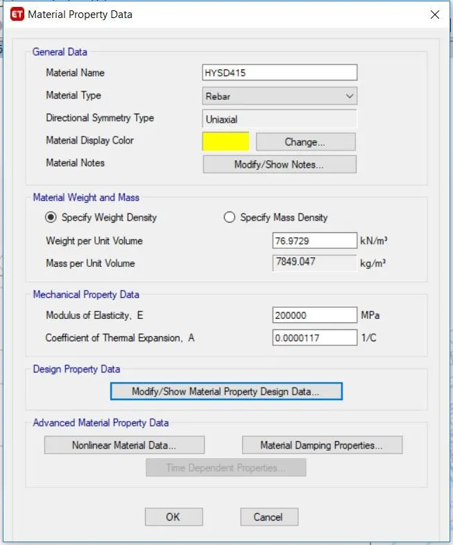
- In the next step, the material has to be defined. Go to define and click on material properties and add the concrete and rebar material specifications.
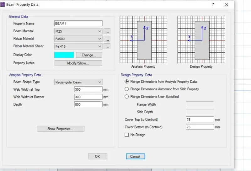
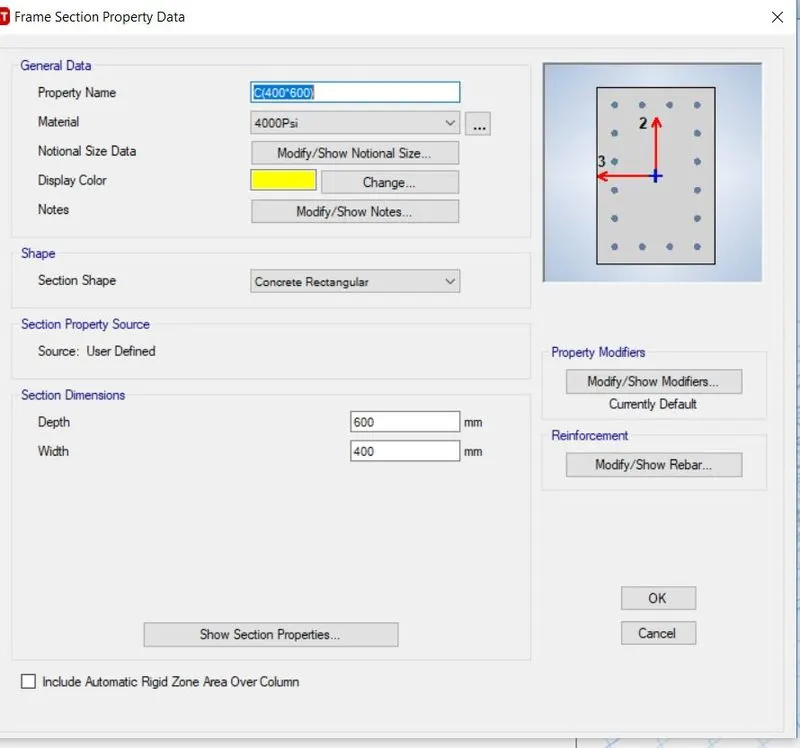
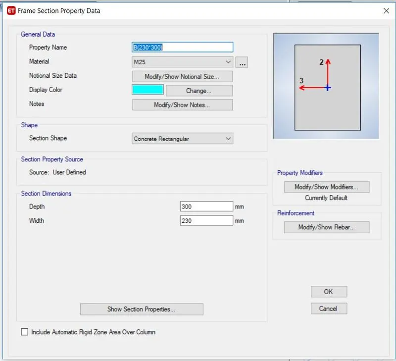
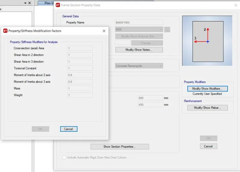
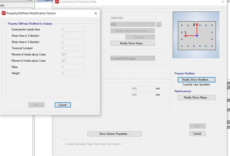
- In the next step, section properties have to be defined. Go to define and click on section properties and add the beam and column specification.
- 450 mm x 600 mm beam size is provided for all the beams.
- 450 mm x 600 mm beams are provided for the beams at the periphery so as to increase the torsional resistance of the building
- The moment of inertia for beams and columns should be reduced by 0.35% and 0.4% respectively.
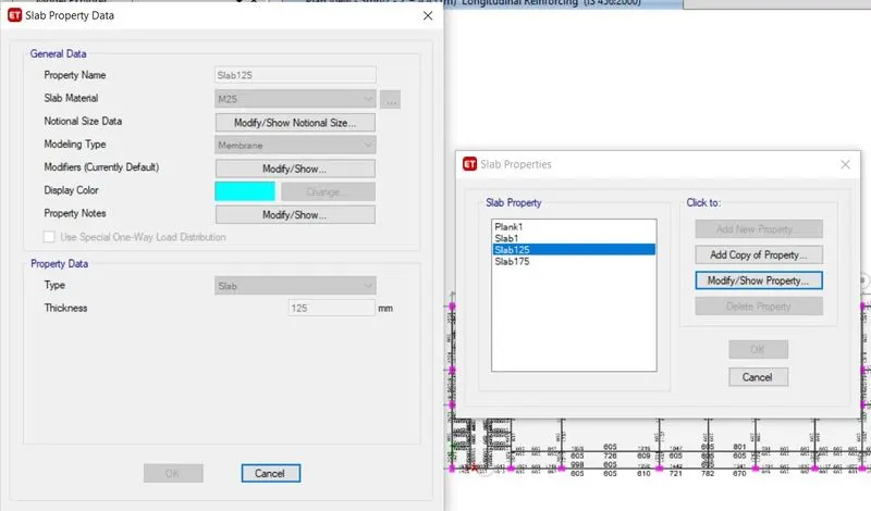
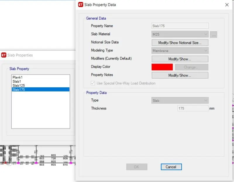
- In the next step define the slab properties by going in to define slab sections. Add the slab property as While defining the slab for Staircase it should be One way.
- Define the staircase slab and provide its thickness as 175 mm( varies from 175-225mm)
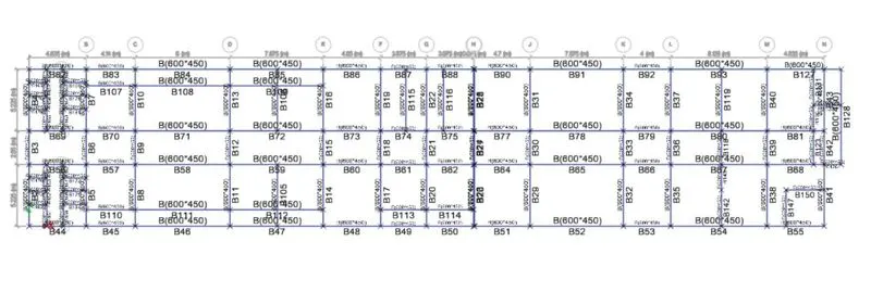
- Draw all the beams using the beam command.
- Draw all the columns using the column command
- In the next step, slabs are drawn using the slabs command
- Now we have to decide the location of the shear walls and how much should be the length of the shear wall.
- As per Indian standards, the length of the wall should be 5-2% in each direction.
- The thickness of the shear wall is assumed to be 250 mm.
- Now go to define and define the loads.
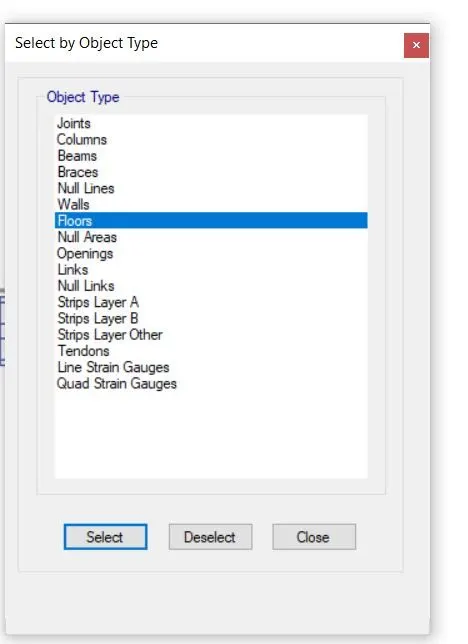
- Next, select the beams and floors and add the loads.
- AAC load of 3.5 kN/m since the aac blocks are used.
- The live load values are got from Is 1875 part 2 for residential buildings.
- As per table 1 of IS 875 part 2
- For hostel buildings
|
Living Rooms, Bedrooms and dormitories |
2 kN/m^2 |
|
Kitchen and Laundries |
3 kN/m^2 |
|
Billiards and public lounges |
3 kN/m^2 |
|
Store rooms |
5 kN/m^2 |
|
Dining rooms, cafeterias and restaurant |
4 kN/m^2 |
|
Office rooms |
2.5 kN/m^2 |
|
Bath and toilets |
2 kN/m^2 |
|
Corridors, passages, staircase |
3 kN/m^2 |
|
Balconies |
4 kN/m^2 |
- As per clause number 875 part 2 reduction factor should be applied to the imposed loads.
- The live load at the roof floor needs to be reduced hence 2 kN/m is applied.
- Floor finish on all the floors 2 kN/m is applied.
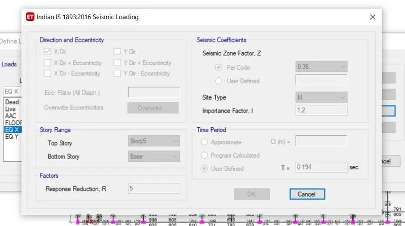
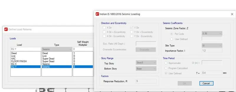
- Seismic loads should be defined so as per IS 1893 Table no. 8 importance factor should be 1.2
- Since the building.
- The time period is calculated as per clause number 7.6.2 of IS 1893
T=0.09h/sqrtd
Tx=(0.09*16.85)/(67.7)^0.5=0.184 Seconds. Or Ty=0.09*16.85/(13.3)^0.5=0.415 sec
- Now define the load combinations
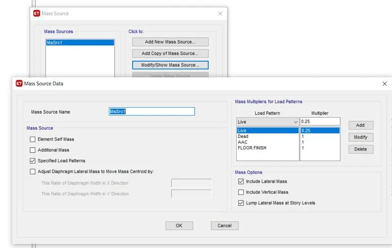
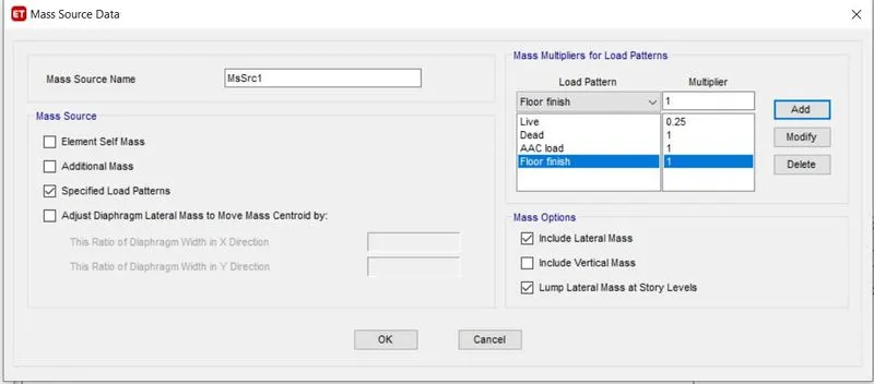
- In the next step we have to define the mass source, for that go to define and click on the mass source and add on the new, and click on specified load data, in the mass options click on include lateral mass and lump lateral mass at story levels, in the load pattern add multiplier 0.25 for LL and 1 for all the dead and super dead loads.
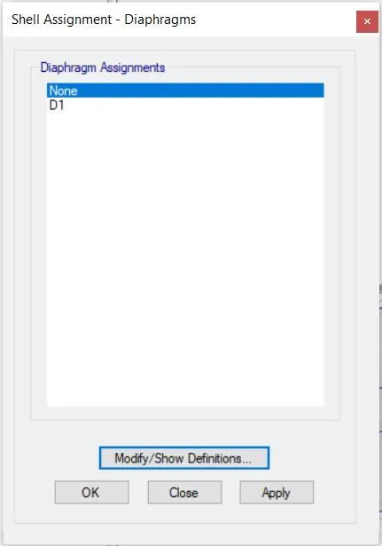
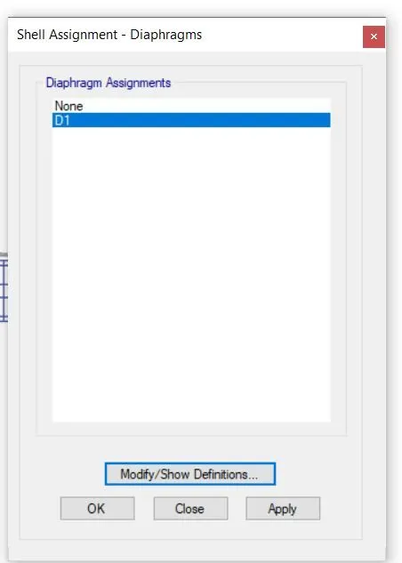
- And select all the floors and apply diaphragm D1
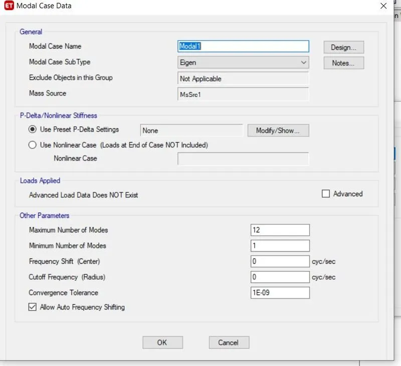
- In the next step we have to define the modal cases for that go to define and click on modal cases click add new model cases select eigen and put the number of modes shape required.
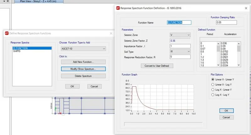
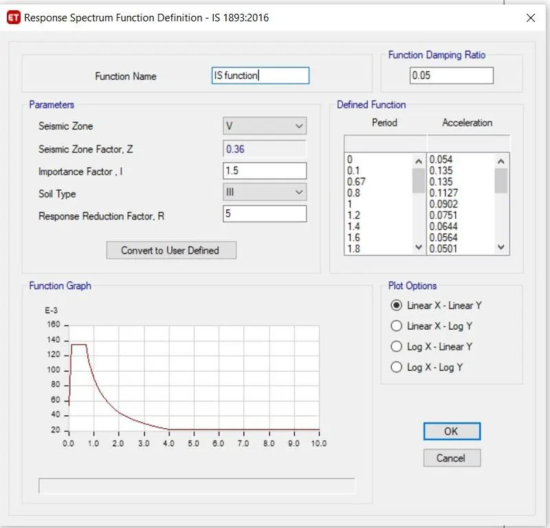
- now go to define the function and click on response spectrum and add a new function in accordance with IS 1893-2016 check all the values and click ok.
- Name the function as IS function, Response spectrum IS function IS 1893-2016 tab will appear to check all the values Seismic zone factor soil type, importance factor click on linear x linear y click ok.
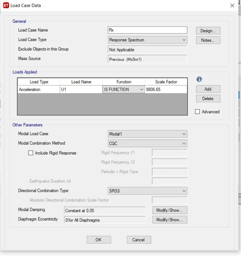
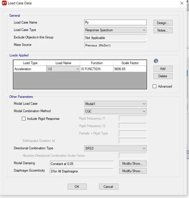
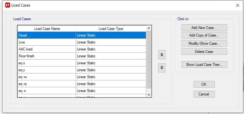
- now go to define Load cases and click on Add the new case and Add RSX and Rsy
- select the response spectrum to click on Add select the function as IS function and U1 for Rx, and U 2 for Rsy and IS function
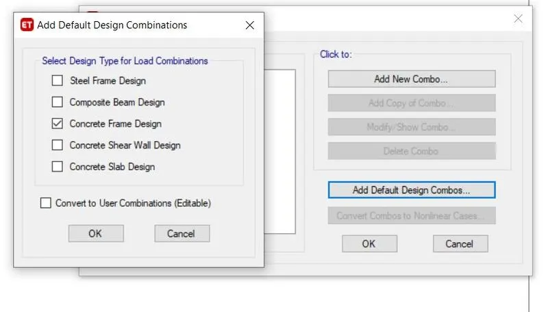
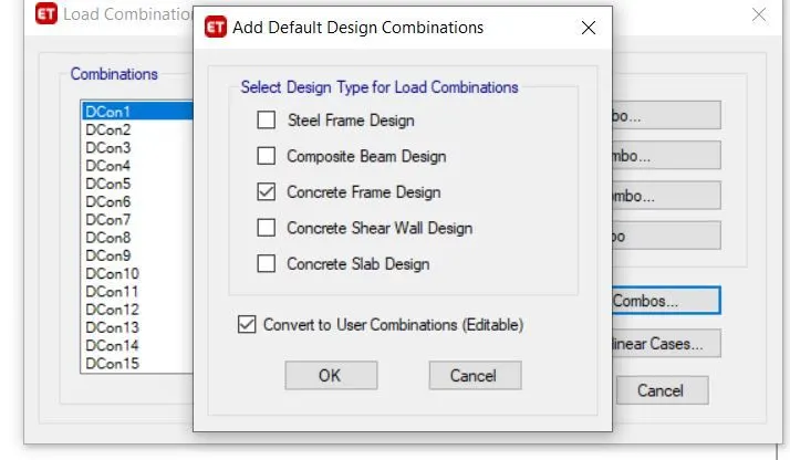
- Go to define click on load combinations and click on default design combo, click on create frame design and click on convert to design combo click ok.
- Now check the model if there are any warnings correct them and run the model.
RESULT:
- Go to display then click show tables and then structural data click ok.
- Click on show tables, select the Analysis results structure output click ok.
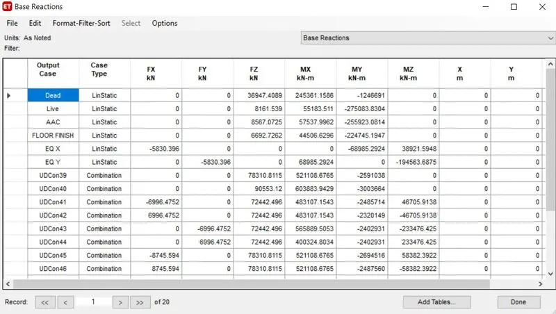
- Select the base reaction and check the eqx eqy values, Rx and Ry values see which values are larger if the rX RY values are lesser than the Eqx Eqy unlock the model and then go to define load case and delete the Rx RY cases and again select the load combinations and define that again.
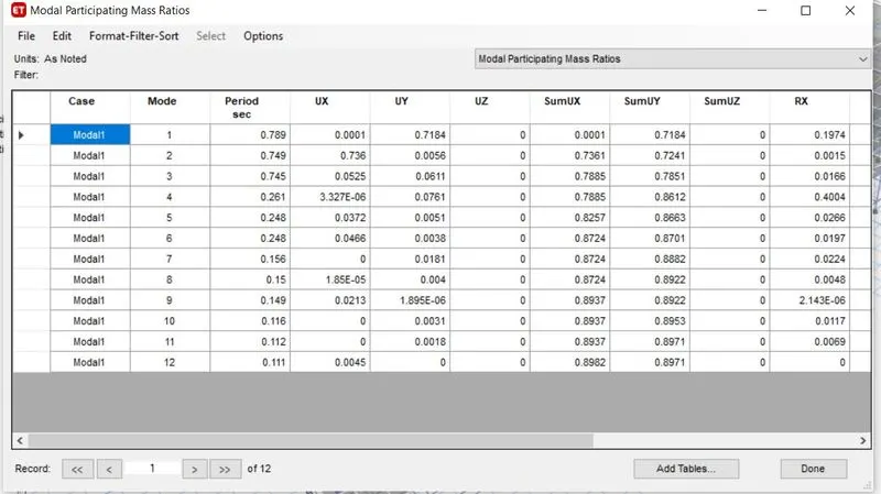
- Go to modal mass participation ratio and check the values for U1 U2 U3 values some of these UX Uy UZ for the first 3 modes it should be greater than 65%.
- Go to concrete frame design and select the start design or check. and note down the vaLues of reinforcement details.
- select modal participating ratios we have got that at mode 7 we have got above 90% so it's okay.
- now select the base reactions to check that Eqx Eqy values should be the same and Rsx and Rsy values also should be at least equal to Eqx and Eqy respectively. if not then just take the Rsx values and divide them by Eq values whatever the values will get that value needs to be multiplied in the load cases Rsx tab.
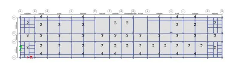
- check for the share of shear walls go to base level and click on reaction Ex and ey values will be available take these values and divide it by the Total base shear which should be greater than 90%. If now add the shear walls in the appropriate directions
 .
.
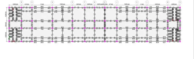
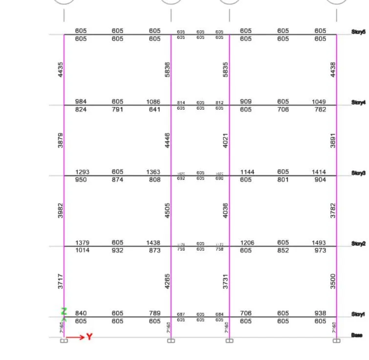

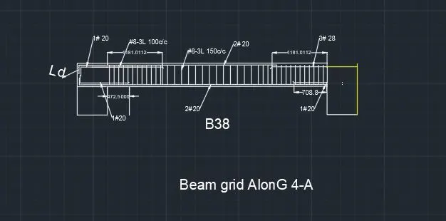
| Beam 14 | Right end | Centre | Left End |
| Bottom Reinforcement | 672 | 605 | 609 |
| required | |||
| Dia of bars | 20 | 20 | 20 |
| Number of bars | 2.140127389 | 1.926751592 | 1.939490446 |
| Bottom Reinforcement | 675 | 605 | 605 |
| Provided at Top | 2.149681529 | 1.926751592 | 1.926751592 |
| 1#24 +2#24 extra is provide | 2#20 is provide | 2#20 is provide |
| COLUMN DESIGN | |||||
| COLUMNS ALONG THE GRID 1B | Column dimension | 450*600 | |||
| 1 | Longitudinal Reinforcement calculation | ||||
| a) | Minimum Reinforcement | 0.8% of the Gross cross-sectional Area | 2160 | mm^2 | |
| As per clause no.26.5.3.1 of Is 456 2000 | |||||
| b) | Maximum Reinforcement | 6% of the Gross cross-sectional Area | 15600 | mm^2 | |
| As per clause no.26.5.3.1 of Is 456 2000 | |||||
| c) | Maximum Ast along 3 A | 4739 | mm^2 | ||
| As per clause no.26.5.3.1 of Is 456 2000 | |||||
| Dia of the longitudinal Reinforcement should be 12 mm or more | |||||
| There for using 16 mm dia bars | |||||
| Dia of bar | 24 | ||||
| Area of 1 bar | 452.448 | ||||
| number of bars | 10.47413183 | ||||
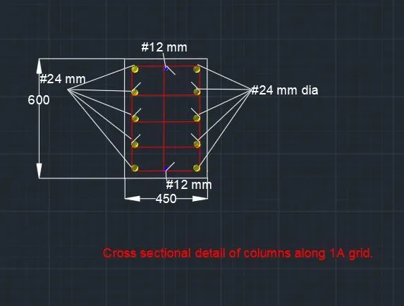
| There fore using 8 28 mm dia bars | Ast | 4524.48 | mm^2 | ||
| remaining St | Ast | 214.52 | mm^2 | ||
| 2 number #12 extra longitudinal Reinforcements need to be provided | Ast | 628 | mm^2 | ||
| There fore total longitudinal reinforcement provided | |||||
| 10 no. of 24 mm dia bars | 4525 | ||||
| 2no. Of 12 mm dia bars | 628 | ||||
| Ast provided | 5152.48 | mm^2 | |||
| The spacing between the longitudinal bars should not exceed 300mm. | |||||
| 2 | Shear Reinforcement calculation | ||||
| a) | Minimum dia for shear Reinforcement for 32 mm dia | 8 mm | |||
| As per clause no 7.4.2 of IS 13290- 2016 | |||||
| b) | Maximum Shear reinforcement from the Etabs output | 665 | mm^2 | ||
| c) | There for using 8 mm dia bars | mm^2 | |||
| Dia of bar | 8 | ||||
| Area of 1 bar | 50.272 | ||||
| Special confining reinforcement clause no 8 of IS 13290 2016 | |||||
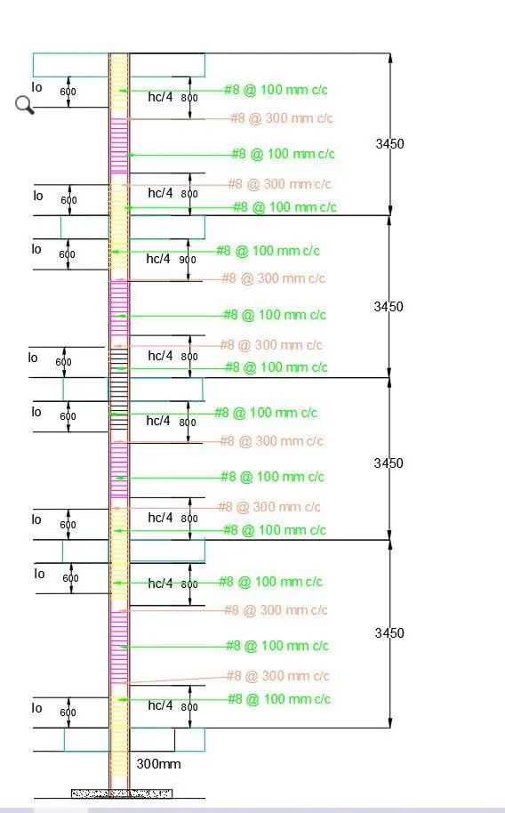
| The special confining reinforcement shall be provided at lo. | |||||
| lo should not be less than | |||||
| the larger lateral dimension of the column | 600 | ||||
| 1/6 of the clear span of the member | 554.1666667 | ||||
| 450 mm | 450 | ||||
| There fore lo = 600 mm | |||||
| The spacing of shear reinforcement along lo should not be more than | |||||
| a | 1/4 of the minimum dimension of the beam/column | ||||
| minimum dimension of the column | 150 | mm | |||
| 1/4th of the minimum dimension of the column | 112.5 | mm | |||
| b | 6 times the dia of the smallest longitudinal reinforcement bar | ||||
| Dia of smallest longitudinal reinforcement bar | 12 | mm | |||
| 6 times the dia of the smallest longitudinal reinforcement bar | 72 | mm | |||
| c | 100 mm | 100 | mm | ||
| Therefore special confining reinforcement #8mm @100 mm c/c is provided in the lo zone. | |||||
| Transverses Reinforcement calculation for the zone up to h/4. | |||||
| hc in m | Beam depth | h | |||
| Height of the column of Plinth level column | 1 | 0.6 | 0.4 | ||
| Height of the column of column | 3.45 | 0.6 | 2.85 | ||
| Height of the column of FF column | 3.45 | 0.6 | 2.85 | ||
| Height of the column of SF column | 3.45 | 0.6 | 2.85 | ||
| Height of the column of TF column | 3.45 | 0.6 | 2.85 | ||
| h | h/4 | approximate | |||
| Plinth level | 0.4 | 0.1 | 200 mm | ||
| GF | 2.85 | 0.7125 | 800 mm | ||
| FF | 2.85 | 0.7125 | 800 mm | ||
| SF | 2.85 | 0.7125 | 800 mm | ||
| TF | 2.85 | 0.7125 | 800 mm | ||
| Transverse reinforcement in the splice Zone as per clause number 7.4.of IS 13290 2016 | |||||
| As per clause no. 7.4.1 of IS 13290 2016 the ends should have 135 hooks with an | |||||
| extension of 6d of bars. | |||||
| d | 32 | mm | |||
| 6d | 192 | mm | |||
| As per the clause nuo. 7.4.2 of IS 13290 2016 | |||||
| a | 8 mm dia bars are used in stirrups if the dia of longitudinal bars is less than or equal to 32 mm | ||||
| b | The maximum c/c spacing of stirrups is 300 mm | ||||
| c | a cross tie should be provided if the dimension of the column exceeds 300 mm. | ||||
| There fore upto h/4 #8mm @300 mm c/cis provided in the lo zone. | |||||
| As per clause no. 7.3.2.1 of IS 13290 2016 | |||||
| 100 mm space should be provided within this splicing zone | |||||
| There fore in the splice zone #8mm @100 mm c/cis provided in the lo zone. | |||||
| For the columns terminating in the footing | |||||
| as per clause nummber 8.2 of IS 13290 2016. | |||||
| special confinement reinforcement should be provided up to 300 mm or larger length inside the footing. | |||||
| COLUMNS ALONG THE GRID 3B | Column dimension | 450*650 | |||
| 1 | Longitudinal Reinforcement calculation | ||||
| a) | Minimum Reinforcement | 0.8% of the Gross cross-sectional Area | 2340 | mm^2 | |
| As per clause no.26.5.3.1 of Is 456 2000 | |||||
| b) | Maximum Reinforcement | 6% of the Gross cross-sectional Area | 17550 | mm^2 | |
| As per clause no.26.5.3.1 of Is 456 2000 | |||||
| c) | Maximum Ast along 3 A | 5022 | mm^2 | ||
| As per clause no.26.5.3.1 of Is 456 2000 | |||||
| Dia of the longitudinal Reinforcement should be 12 mm or more | |||||
| There for using 16 mm dia bars | |||||
| Dia of bar | 28 | ||||
| Area of 1 bar | 615.832 | ||||
| number of bars | 8.154821445 | ||||
| There fore using 8 32 mm dia bars | Ast | 4926.656 | |||
| Remaning Ast | Ast | 95.344 | |||
| There for using 16 mm dia bars | |||||
| Dia of bar | 16 | ||||
| Area of 1 bar | 201.088 | ||||
| number of bars | 0.474140675 | ||||
| There fore using 2 20 mm dia bars | Ast | 402.176 | |||
| There fore total longitudinal reinforcement provided | |||||
| 8 no. of 28 mm dia bars | |||||
| 2no. Of 16 mm dia bars | |||||
| Ast provided | 5328.832 | mm^2 | |||
| The spacing between the longitudinal bars should not exceed 300mm. | |||||
| 2 | Shear Reinforcement calculation | ||||
| a) | Minimum dia for shear Reinforcement for 32 mm dia | 8 mm | |||
| As per clause no 7.4.2 of IS 13290- 2016 | |||||
| b) | Maximum Shear reinforcement from the Etabs output | 720.48 | mm^2 | ||
| c) | There for using 8 mm dia bars | mm^2 | |||
| Dia of bar | 8 | ||||
| Area of 1 bar | 50.272 | ||||
| Special confining reinforcement clause no 8 of IS 13290 2016 | |||||
| The special confining reinforcement shall be provided at lo. | |||||
| lo should not be less than | |||||
| the larger lateral dimension of the column | 650mm | ||||
| 1/6 of the clear span of the member | 554.1666667 | ||||
| 450 mm | 450 | ||||
| There fore lo = 650 mm | |||||
| The spacing of shear reinforcement along lo should not be more than | |||||
| a | 1/4 of the minimum dimension of the beam/column | ||||
| minimum dimension of the column | 450 | mm | |||
| 1/4th of the minimum dimension of the column | 112.5 | mm | |||
| b | 6 times the dia of the smallest longitudinal reinforcement bar | ||||
| Dia of smallest longitudinal reinforcement bar | 20 | mm | |||
| 6 times the dia of the smallest longitudinal reinforcement bar | 120 | mm | |||
| c | 100 mm | 100 | mm | ||
| Therefore special confining reinforcement #8mm @100 mm c/c is provided in the lo zone. | |||||
| Transverses Reinforcement calculation for the zone up to h/4. | |||||
| hc in m | Beam depth | h | |||
| Height of the column of Plinth level column | 1.5 | 0.5 | 1 | ||
| Height of the column of column | 4 | 0.5 | 3.5 | ||
| Height of the column of FF column | 3.45 | 0.5 | 2.95 | ||
| Height of the column of SF column | 3.45 | 0.5 | 2.95 | ||
| Height of the column of TF column | 3.45 | 0.5 | 2.95 | ||
| 3.45 | 0.5 | 2.95 | |||
| h | h/4 | approximate | |||
| Plinth level | 1 | 0.25 | 300 mm | ||
| GF | 3.5 | 0.875 | 900 mm | ||
| FF | 2.95 | 0.7375 | 900 mm | ||
| SF | 2.95 | 0.7375 | 900 mm | ||
| TF | 2.95 | 0.7375 | 900 mm | ||
| Transverse reinforcement in the splice Zone as per clause number 7.4.of IS 13290 2016 | |||||
| As per the clause nuo. 7.4.1 of IS 13290 2016 the ends should have 135 hooks with an | |||||
| extension of 6d of bars. | |||||
| d | 32 | mm | |||
| 6d | 192 | mm | |||
| As per the clause nuo. 7.4.2 of IS 13290 2016 | |||||
| a | 8 mm dia bars are used in stirrups if the dia of longitudinal bars is less than or equal to 32 mm | ||||
| b | The maximum c/c spacing of stirrups is 300 mm | ||||
| c | a cross tie should be provided if the dimension of the column exceeds 300 mm. | ||||
| There fore upto h/4 #8mm @300 mm c/cis provided in the lo zone. | |||||
| As per clause no. 7.3.2.1 of IS 13290 2016 | |||||
| 100 mm spacing should be provided within this splicing zone | |||||
| There fore in the splice zone #8mm @100 mm c/cis provided in the lo zone. | |||||
| For the columns terminating in the footing | |||||
| as per clause nummber 8.2 of IS 13290 2016. | |||||
| special confinement reinforcement should be provided up to 300 mm or larger length inside the footing. |
Importing the software Safe 2016
- Go to file click on export and select the safe v12.fk.
- A tab will appear then click on the story as a base and select the loads and loads from above click on the combination click ok,
- Goto SAFE 2016 and fo to file click import and select the file and save the file as FDB.
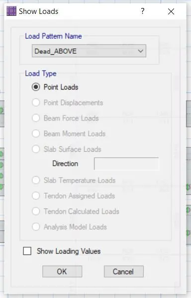
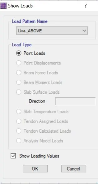
- Go to display click on the show loads select dead above and love above the values will be appeared.
GIVEN DATA:
Column of size:- 450mm *600 mm & 600mm*450m m
the pile has a load-carrying capacity of 280kN
Pile length-16 m and dia of pile -500 mm
SBC-150kN/m^2
SOLUTION:
- Number of piles=Total Axial load/pile capacity=(1.5DL+1.5LL)/280= numbers
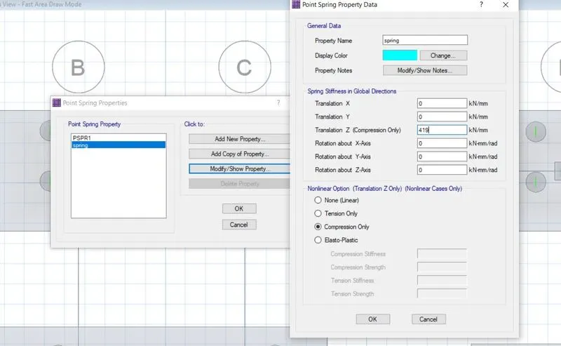
- Piles in the springs are defined as spring so for that the spring constant
K=EA/L
E=5000(fck)^0.5=5000(25)^0.5=25000 N/mm^2
Area of pile =22/7*d^2=3.142*(500)^2/4=196375m^2
L-10000m
K=25000*0.7855/16=306835.9N/mm==419.
- Spacing of the piles as per clause number 6.6.2 of IS 2911 the spacing between the piles =2.5dia of the piles =2.5*500=1250mm
- Now in the next step, we have to define the material properties for go to define and define the material properties of Concrete and Reinforcement properties Fe500 & Fe 415.
- Select the values.
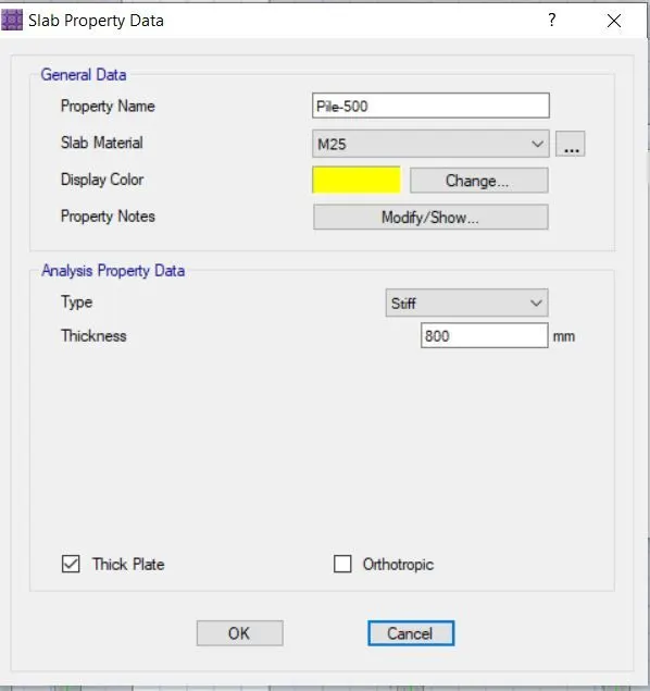
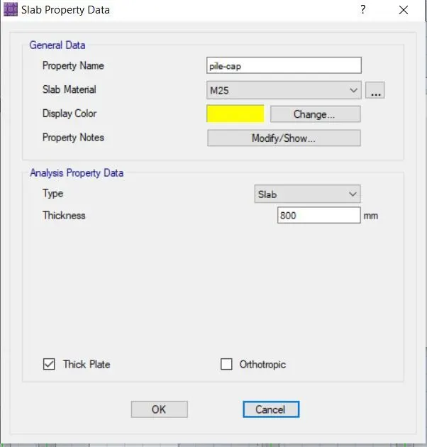
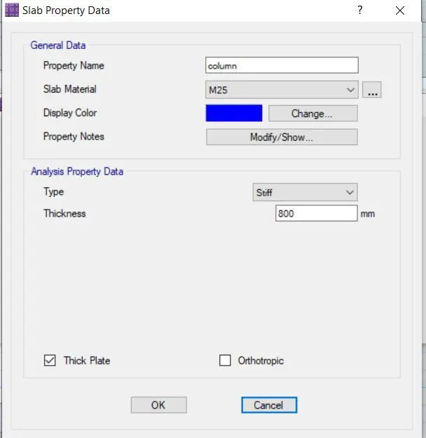
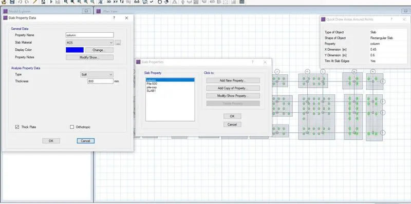
- Go to define section properties and define pile caps, pile Dia, and column
- Add new, defined pile cap pile 500 as Mat, and Column as Stiff.
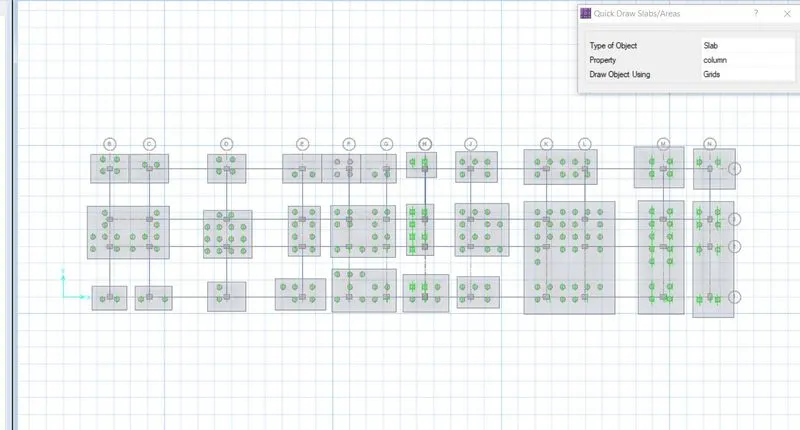
- Click on the quick draw around the plots a window will open there insert the columns sizes and these columns to their specified positions. Columns should be stated as stiff material.
- In the next step pile caps needs to be drawn for that go to the Quickdraw slab command select pile caps and add it. Piles and pile caps should be stated as stiff material.
- Select the pile caps and changed the rebar material to Fe 500.
- Next, go to draw and draw points and a window will open up there draw the points where piles are to be drawn.
- Now again select the quick draw around the pints there select the property circular slab to add piles dia in this case 0.5m and add to the points. Select these piles and again check for the rebar materials.
- Now we have to define all the piles as springs for that goes to define
- select soil spring properties add new property there click on compression only and add the calculation value of K=EA?L.
- Select all the piles and go to assign and select support data and select spring properties and assign it.
- Go to define and select the defined beam and define the tie beams whose thickness should be as of pile caps.
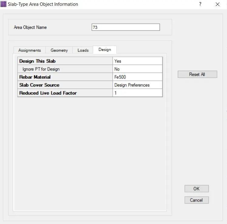
- Check whether the rebar material is Fe 500 under design preferences
- Go to define and define the load combinations sls and uls
- Go to design and design preferences
- Save the model and run the Analysis
- Deformed shapes showed that deformations are negligible
- Assign add the design strips
- Run the analysis
- Deformed shape all the values are less than 25 mm hence ok.
- Now go to display and click on the punching shear the values we have to go are less than 1 hence ok.
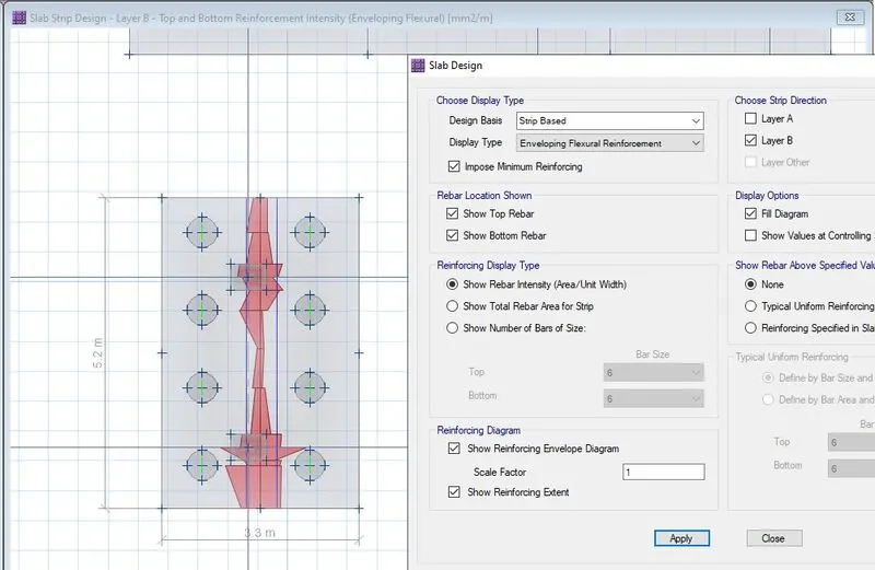
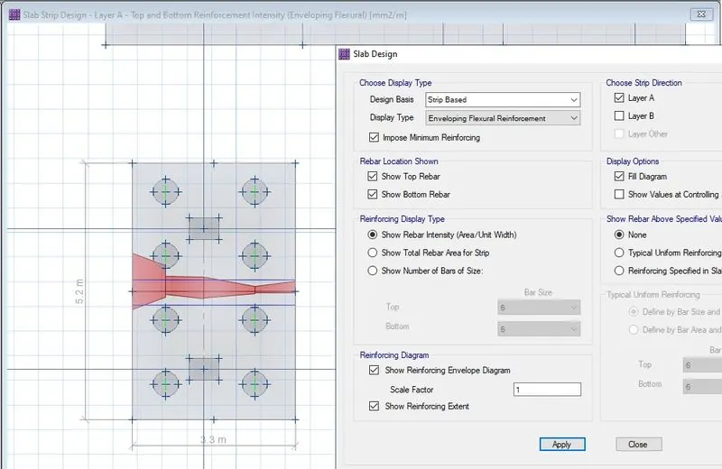
- Now go to display and select slab design.
- All the reinforcement details will be available
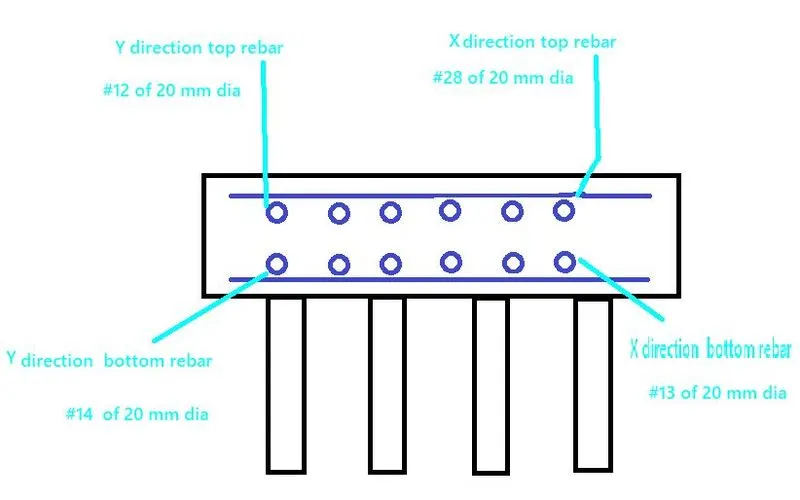
- For X DIRECTION MIDDLE STRIP
maximum Reinforcement was
For Top:- 29834 mm^2/m=29834/3.3=9041 mm^2=28 nos. 20 mm dia are provided
For Bottom-13326mm^2/m=4038 mm^2=13 nos., 20 mm dia are provided
- For layer Y direction
maximum Reinforcement was
For Top:- 19926= 3831mm^2/m=12 nos of 20 mm dia are provided
For Bottom-22784mm^2/m=4398 mm^2=14 nos 20 mm dia are provided