Project 2_Creating a 3D rendered model for a Residential Building in AutoCad
AIM: To create a 3-dimensional model of the residential building with a rendered view in AutoCAD.
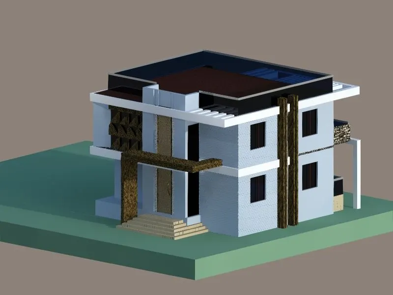
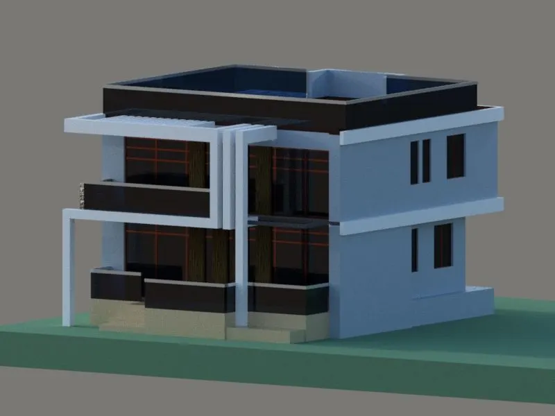
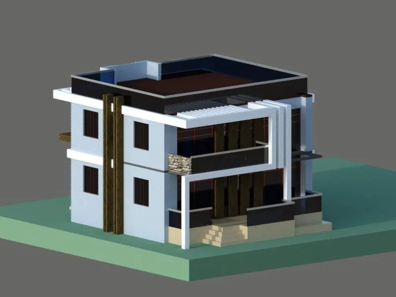
INTRODUCTION: Rendered view of the G+1 residential building is designed for this project.
In this project, the Main objective is the usage of rendering in AutoCAD by giving correct materials, lights, view and rendering property.
RENDERING is a process of generating the 2d or 3d model into a photorealistic or non-photo-realistic image using a computer program.
It is useful to show the final result of the model.
Following rendering there are some more important 3d tools are used to do this model.
PROCEDURE:
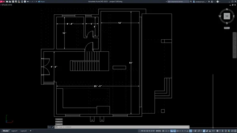
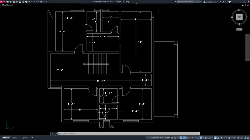
- Initially, we need to plot a 2d plan of a residential building that needs to be worked on with respect to its dimension.
- Ground floor:
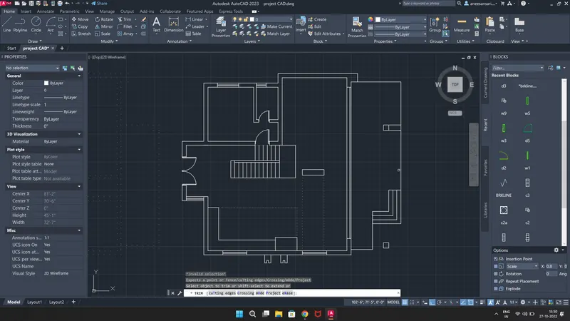
- First floor:
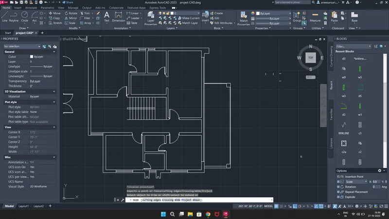
- Ground floor:
- Create the layers that we need in the 3d model as follows. The plan will remain in the 0 layers.
Name Status On Freeze Lock Plot Colour Linetype Lineweight Transparency 0 kCurrent TRUE FALSE FALSE TRUE white Continuous ByLineWeightDefault 0 CLAD WOOD kUsed TRUE FALSE FALSE TRUE 152,98,3 Continuous ByLineWeightDefault 0 clad wood 2 kUsed TRUE FALSE FALSE TRUE 117,74,6 Continuous ByLineWeightDefault 0 Defpoints kUsed TRUE FALSE FALSE FALSE white Continuous ByLineWeightDefault 0 doors kUsed TRUE FALSE FALSE TRUE white Continuous ByLineWeightDefault 0 external stairs kUsed TRUE FALSE FALSE TRUE 255 Continuous ByLineWeightDefault 0 GLASS kUsed TRUE FALSE FALSE TRUE 140 Continuous ByLineWeightDefault 0 handle kUsed TRUE FALSE FALSE TRUE 64 Continuous ByLineWeightDefault 0 LAND kUsed TRUE FALSE FALSE TRUE 107 Continuous ByLineWeightDefault 0 Layer1 kUsed TRUE FALSE FALSE TRUE 25,52,55,255 Continuous ByLineWeightDefault 0 parapet kUsed TRUE FALSE FALSE TRUE 8 Continuous ByLineWeightDefault 0 rack kUsed TRUE FALSE FALSE TRUE 9 Continuous ByLineWeightDefault 0 SLAB 1 kUsed TRUE FALSE FALSE TRUE white Continuous ByLineWeightDefault 0 SLAB CLAD kUsed TRUE FALSE FALSE TRUE 40 Continuous ByLineWeightDefault 0 walls kUsed TRUE FALSE FALSE TRUE 9 Continuous ByLineWeightDefault 0 window frame kUsed TRUE FALSE FALSE TRUE 210 Continuous ByLineWeightDefault 0 windows kUsed TRUE FALSE FALSE TRUE 80 Continuous ByLineWeightDefault 0 - Following this, the plan 3d modelling is started.
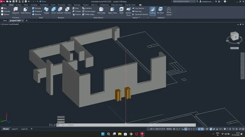
- First, we have to extrude the walls from the plan. Interior wall thickness=6" , Exterior wall thickness=9"
- Using region command make the wall area as a region and extrude it up to 3' by leaving space for the main door and back entrance.
- Window height is 5' on both floors, So sil level is 8' from the floors. (Floor height=10')
- Provide sil for all the windows and union the body.
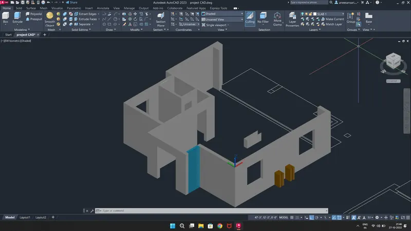
- Provide a Slab for the first floor by using the 1st-floor plan and extrude it for 5" thickness.
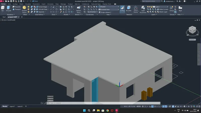
- In the same way as the ground floor, create the first floor at 10' in height and provide a slab to it.
- Leave space for windows and doors in the wall while extruding.
- Provide a floor with a thickness of 3' by using the respective layer.
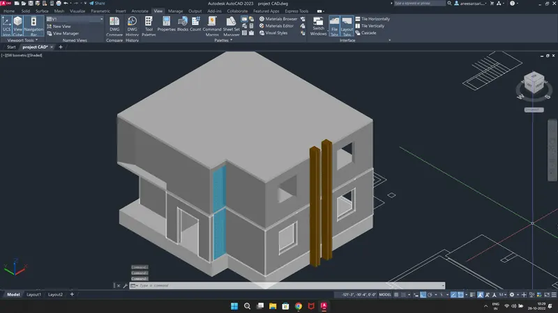
- And now it's time to provide architectural elements to the building.
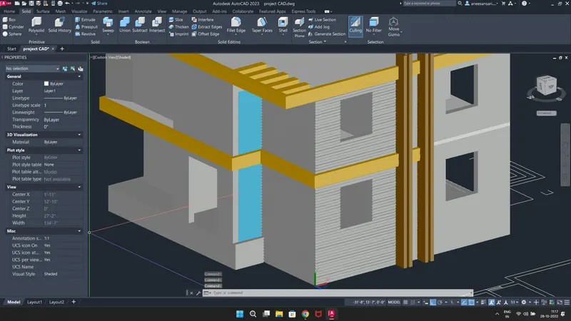
- Provide fake beams, fake columns and borders with the respective layer and colours to the slab as shown in the figure.
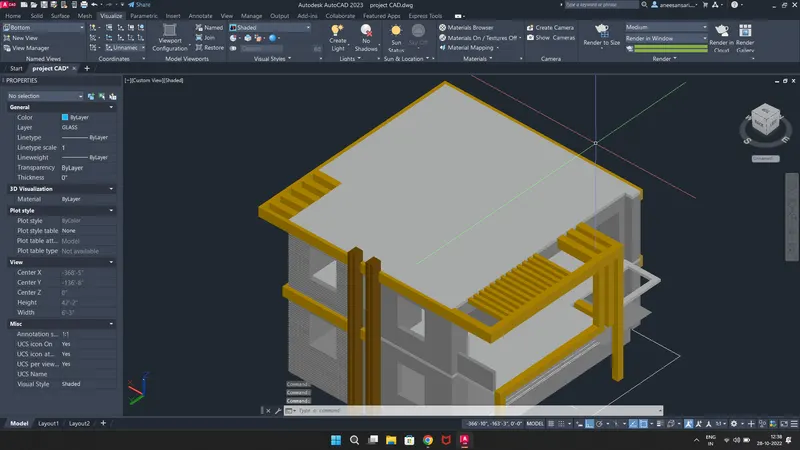
- Provide texture on the front wall by subtracting solids:
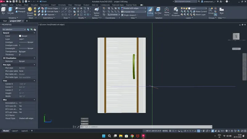
- Make a door which suits the building and provide a handle to it seperatly.
- For the front wall, we need to provide more aesthetic, and architectural elements. So, make a square which is a combination of cladding and glass and place it at the first-floor wall.
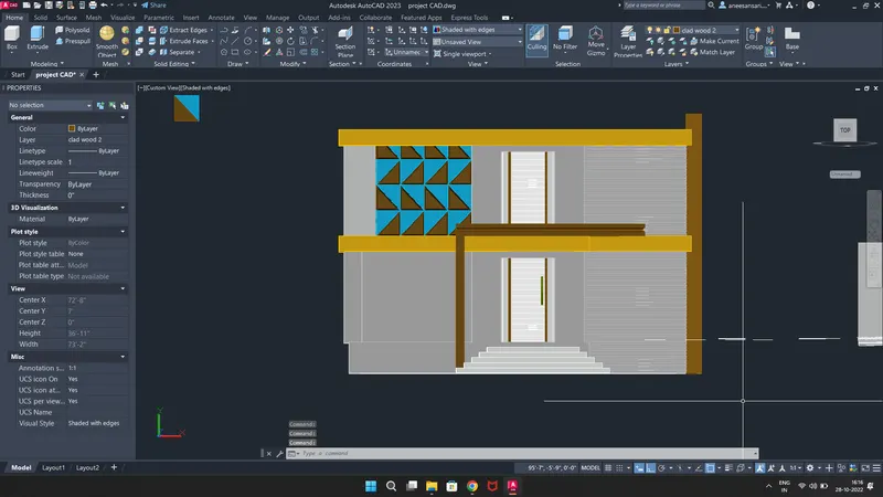
- Provide fake beams, fake columns and borders with the respective layer and colours to the slab as shown in the figure.
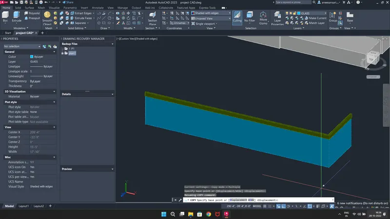
- Provide parapet wall to the building by using glass.
- Use polysoild command to make the glass.
- Making of windows.
- Note the size of windows as using sweep make window frames in 2"x2".
- Provide mullians where they are required.
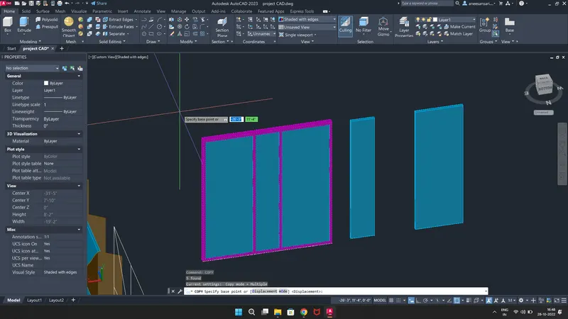
- And in end provide glass to the window frames and place the where they belongs to.
Left side: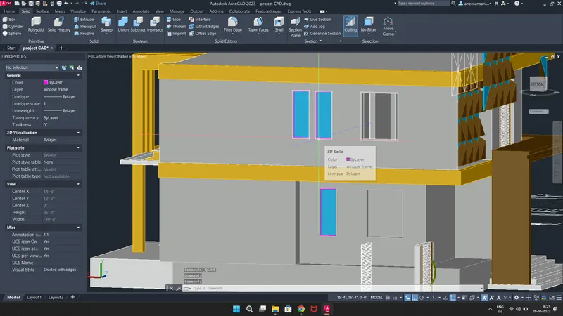
Right side: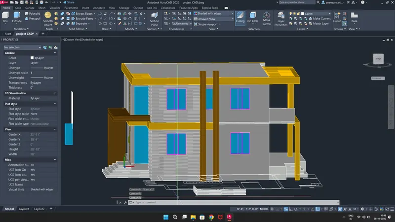
Isometric from front: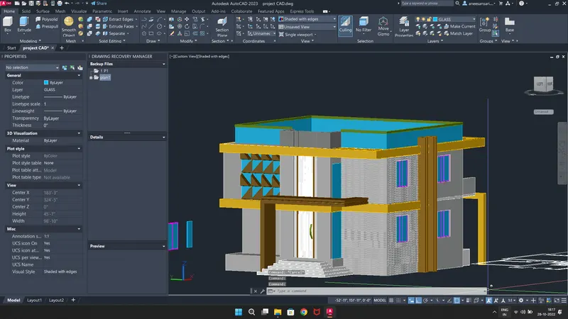
- Note the size of windows as using sweep make window frames in 2"x2".
- Now Provide the glass doors in both floors including wooden decorative cladding walls:
- First make the frames for those doors and place mullians in between using PULLPUSH & SWEEP command"
- Now make the Wooden cladding by subtracting solids to get that texture and place them accordingly in middle of glass doors.
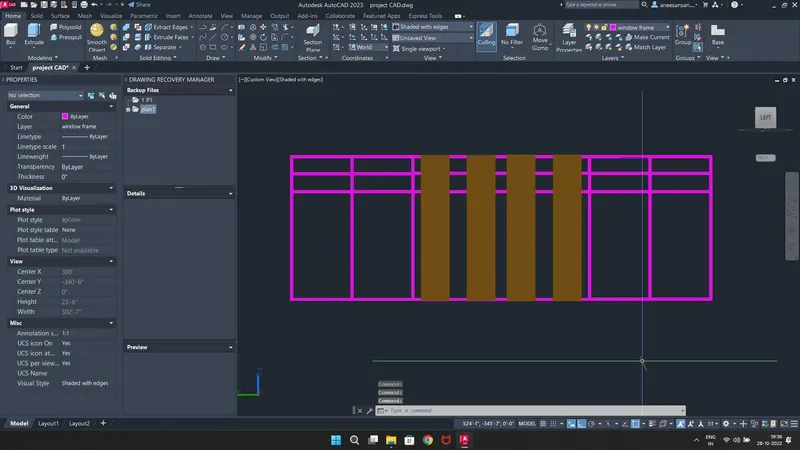
- Place a glass of 1" thickness in between.
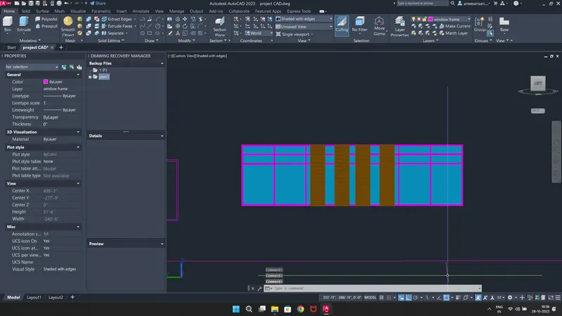
- Height of first floor glass doors is 8'.
- Height of ground floor glass doors is 10'.
- Place them in the places where they belongs to: (turn of layers temporarily to work smoothly)
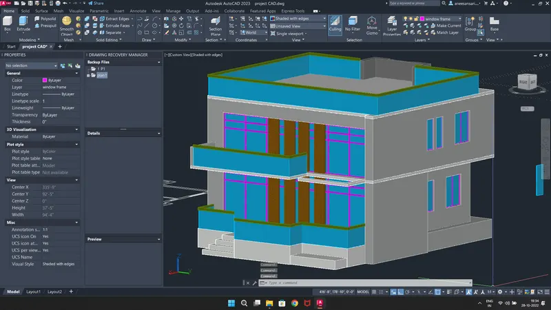
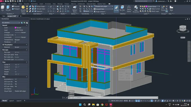
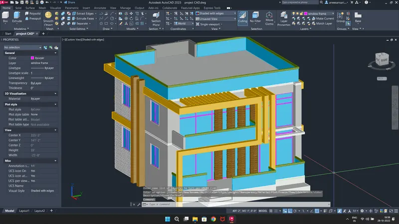
- Provide ground for the model for better look.
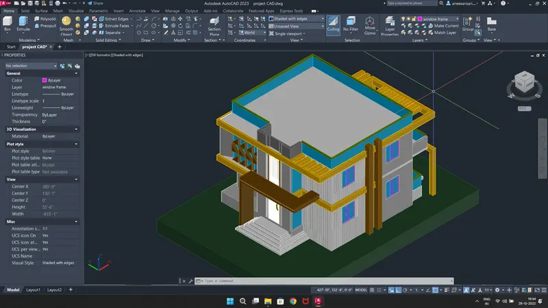
- Modelling part is done now. Its time to provide lights to the building. For that go visualiser tab.
- Provide point spot lights around the building in required intensity and properties.
- Provide spot lights around the building by creating a tall cylinders and place on them with required intensity.
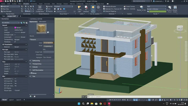
- Providing materials:
- In material browsers in visualiser tab we can find number of materials that we can use for the building.
- Edit material properties as desired.
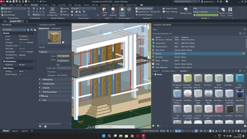
- Provide materials at required places respectively.
- Rendering time:
- In visualiser tab, go to render and provide the render environment and other properties to render the model. Set the camera angle perfectly as desired.
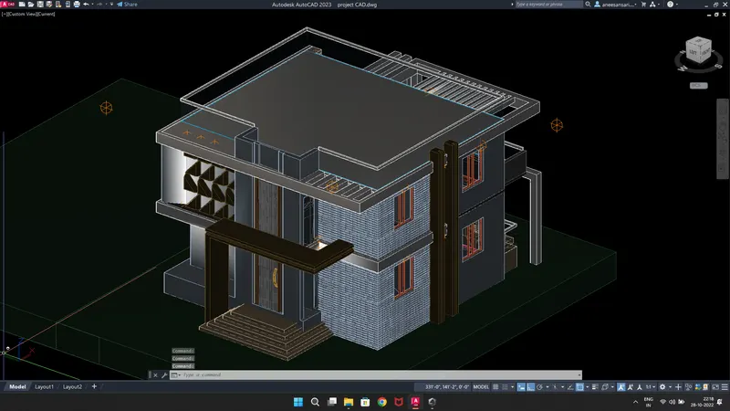
- Take a sample renders to check the quality.:
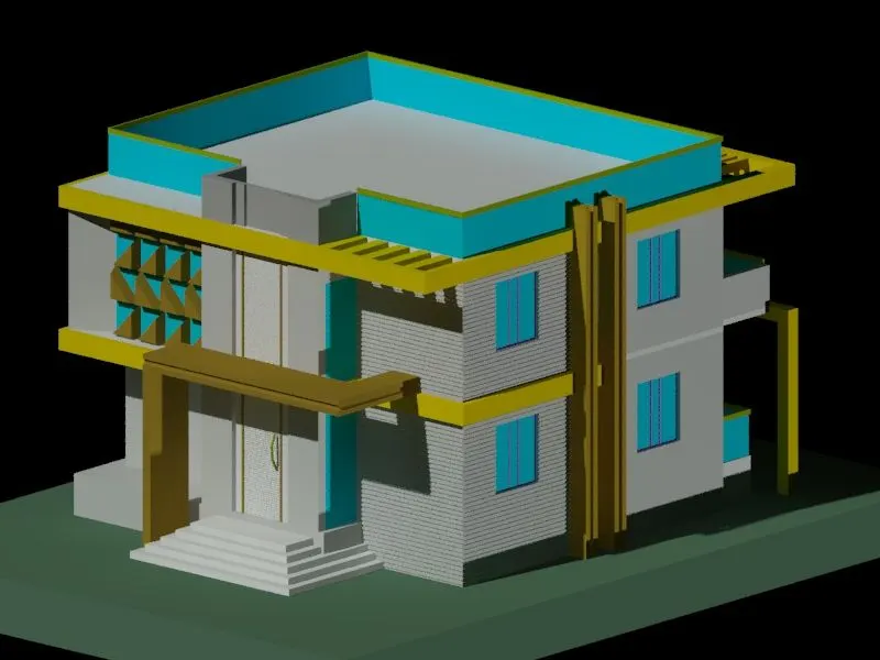
- In visualiser tab, go to render and provide the render environment and other properties to render the model. Set the camera angle perfectly as desired.
- Finally go to layouts and create multiple view ports to show the detailed view of model in single sheet.
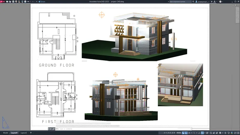
- SAVE THE MODEL AND CLOSE TH APPLICATION.
RESULT: