Drafting of various geometries using Chamfer, Fillet tool in AutoCad
Drafting of various geometries using Chamfer, Fillet tool in AutoCAD.
1
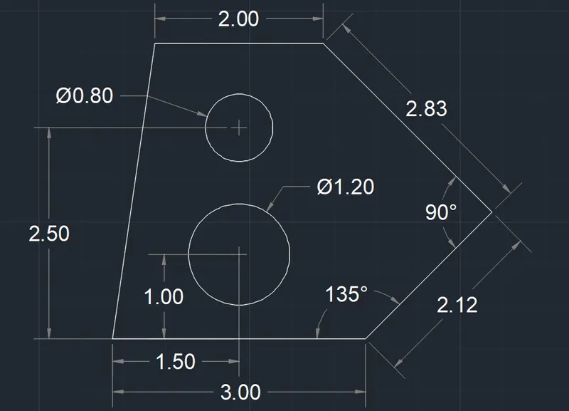
AIM: To create the given geometry using some tools in AutoCAD
INTRODUCTION: In this geometry various tools, options and commands are used.
Most importantly snap tools are used while drawing this geometry.
Commands used are:
- Polyline
- Circle
- Mid of
PROCEDURE:
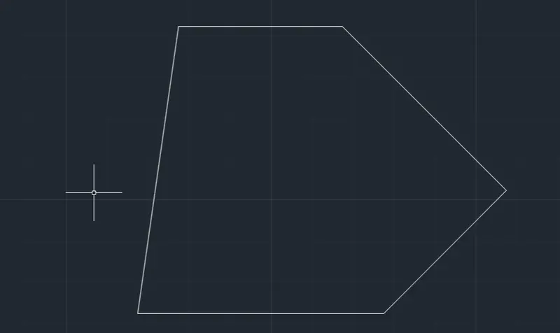
- First, start the line at any point 1 in the AutoCAD window and follow the below points in order to create the outer geometry.
- point 2: @3<0
- point 3: @2.12<45
- point 4: @2.83<135
- point 5: @2<180
- And press C to close the geometry.
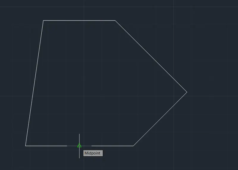
- And next use the snap tool in the status bar, toggle the midpoint option on
- Go to the centre of the bottom line and drag the reference line up to 1 unit to the top
- Create the circle of 1.2 units dia
- Go to the centre of the bottom line and drag the reference line up to 2.5 units to the top and create a circle of 0.8 units dia.
- Press 'ESC' to complete the geometry
RESULT:
2
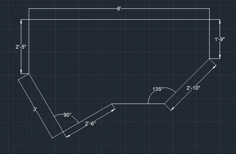
AIM: To create the geometry as shown in the figure using some tools in AutoCAD
INTRODUCTION: The tools/commands which are used to draw this geometry are:
- Polyline
- Rotate
- Move
- End of
- Units
PROCEDURE:
- First, change the units from decimal to Architectural.
- Then draw the upper geometry i.e start the polyline at any point 1 and then:
- Point 2 @ 2'5"<90
- Point 3 @ 8'<0
- Point 4 @ 1'9"<270
- Then draw the lower geometries separately :
- Left-hand side:
- Start at any point
- And draw a 3' line to the bottom then a 2'6" line to the 90 degrees right
- Right-hand side:
- Draw a 2'10" line to the bottom
- And extend the line to the right at 135 degrees dia.
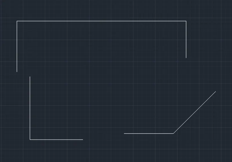
- Using the move tool brings both of their endpoints to the upper geometry
- Using rotate command and taking the base point as the intersection point of 1st and second geometry join them.
- The baseline of the right geometry should be horizontal.
- ESC
- Left-hand side:
RESULT:
3
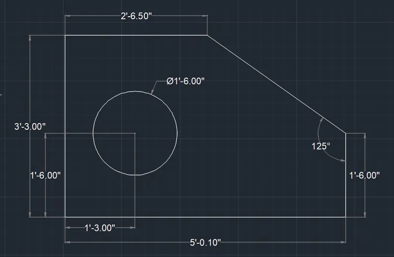
AIM: To Create the geometry as shown in the figure using AutoCAD
INTRODUCTION: The commands and tools used in this geometry are:
- Polyline
- Circle
- Snap reference
- End of
- offset
PROCEDURE:
- First, create the outer geometry with polyline:
- Point 1 @ random
- Point 2 @ 2'6.5"<180
- Point 3 @ 3'3"<270
- Point 4 @ 5'0.1"<0
- Point 5 @ 1'6"<90 and press 'C' to close the geometry
- And then draw the offset of the line 3'3" to the distance of 1'3" inwards.
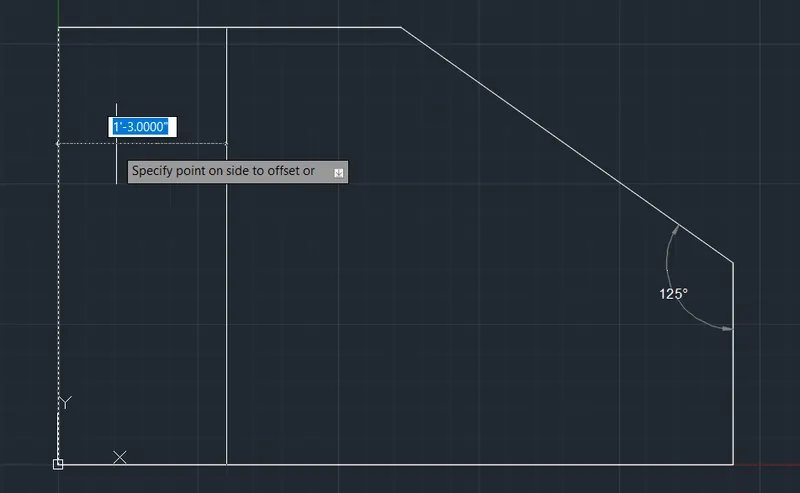
- Take the reference line of the end of 1'6" to the offset and draw the circle of dia 1'6"
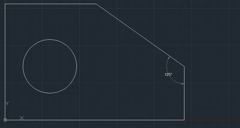
- ESC
RESULT:
4
AIM: To draw the geometry using projectors in AUTOCAD.
INTRODUCTION: In this given geometry we should mainly use the XLINE command
Commands used:
- XLINE hor
- XLINE ver
- trim
PROCEDURE:
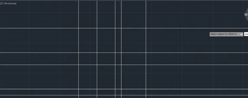
- At first, take the X line command and draw a horizontal random line.
- create the offsets to the top for horizontal lines in the following distances :
- 0.50
- 2.50
- 3.50
- 5.50
- In the same way, create a vertical random line on it and take create offsets to the left side for that as follow:
- 2.00
- 4.50
- 2.50
- And then trim the unwanted outer and inner lines as shown in the figure of the question.
- ESC.
RESULT: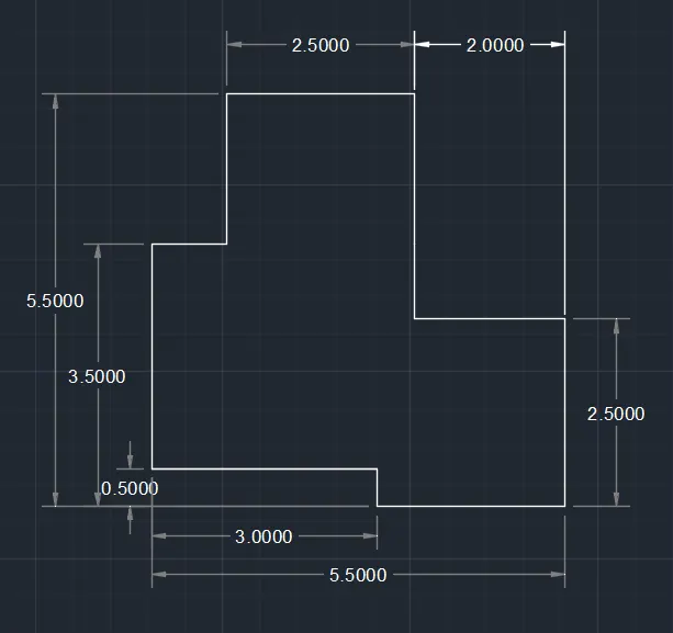
5
AIM: To create the geometry using tools of AUTOCAD
INTRODUCTION: To create this geometry tools that are used are:
- Rectangle
- Line
- Circle
- Snap
- Mid of
- centre of
- COPY
PROCEDURE:
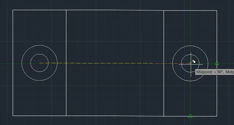
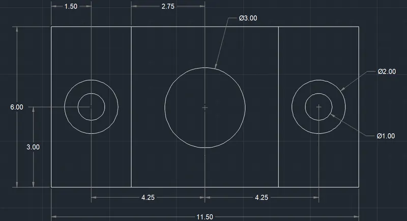
- Start with a rectangle of a length of 3 and a width of 6 units.
- Copy the rectangle to 8.5 units distance horizontally.
- Join the rectangles with a line
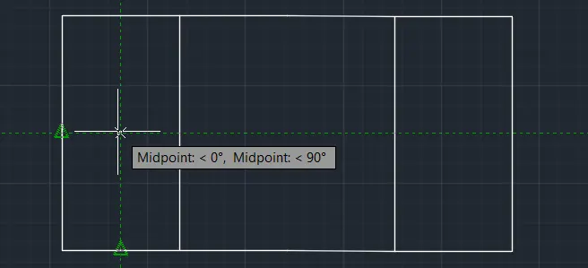
- With the help of mid-of snap draw the circles of dias 2 and 1 unit in the centre of both the rectangles and dia of 3 units in between the rectangles
RESULT:
6
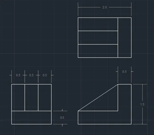
AIM: To draw the 3D Model of given geometry using AutoCAD.
INTRODUCTION: To draw this geometry the following commands are used:
- X LINE
- line
- trim
PROCEDURE:
- Start the horizontal x line and draw 10 offsets to that with intervals of 0.5 units
- Start the Vertical x line and draw 10 offsets to that with intervals of 0.5 units
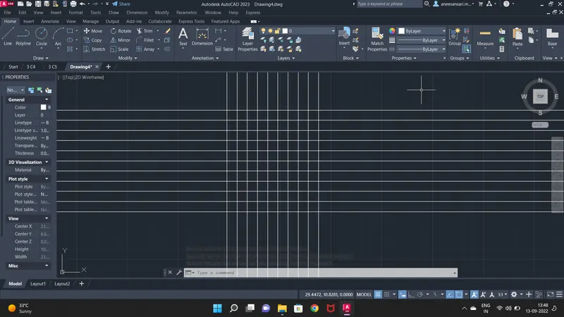
- Draw the inclination as shown in the figure and trim all unwanted lines.
- ESC
RESULT:
7
AIM: To create the geometry using a different kinds of tools in AUTOCAD
INTRODUCTION: To draw this geometry many tools are used, they are:
- line
- Offset
- Curve: start end radius
- fillet
- trim
- snap: centre of, mid of, end of
PROCEDURE:
- Draw the horizontal line of 210 units
- Draw the offset of the line downwards in intervals of 10,40,20 units
- Draw the vertical line of 100 units on the left end and 75 units in the right end
- Using offset draw the rectangles inside the geometry as shown below:
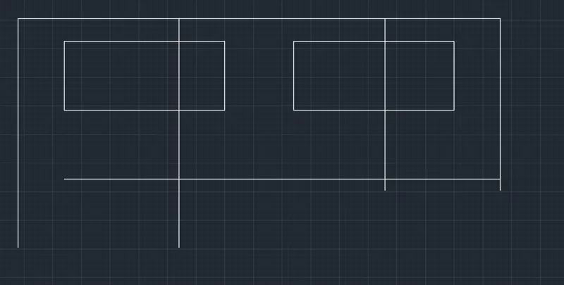
- Then trim the useless lines.
- Draw the offset of 100 units lines inward to 70 units and 75 units lines to 50 units and trim the extensions.
- Draw the curve at the bottom opening with help of start-end radius curves.
- Radius left = 35
- radius right = 25
- Draw circles inside those curves using the centre of the snap tool with radius:
- left=25
- right=15
- Then draw a fillet for every corner in the required radius:
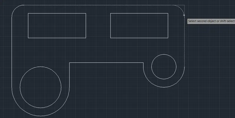
- ESC
RESULT: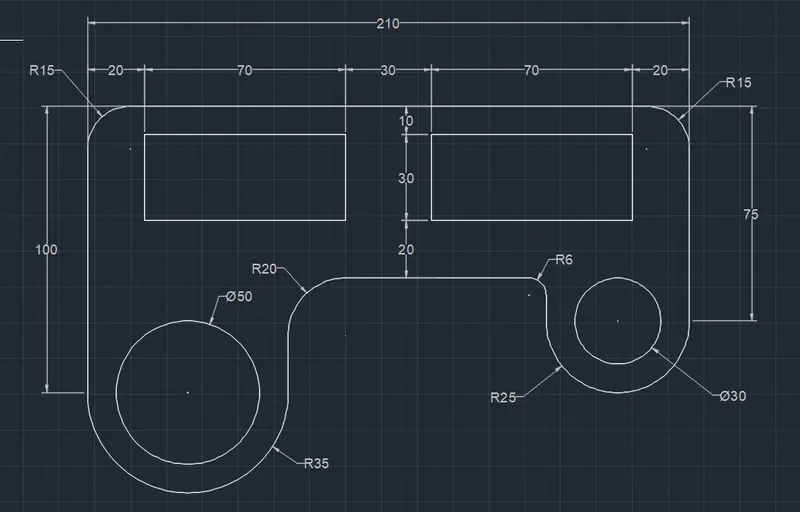
8
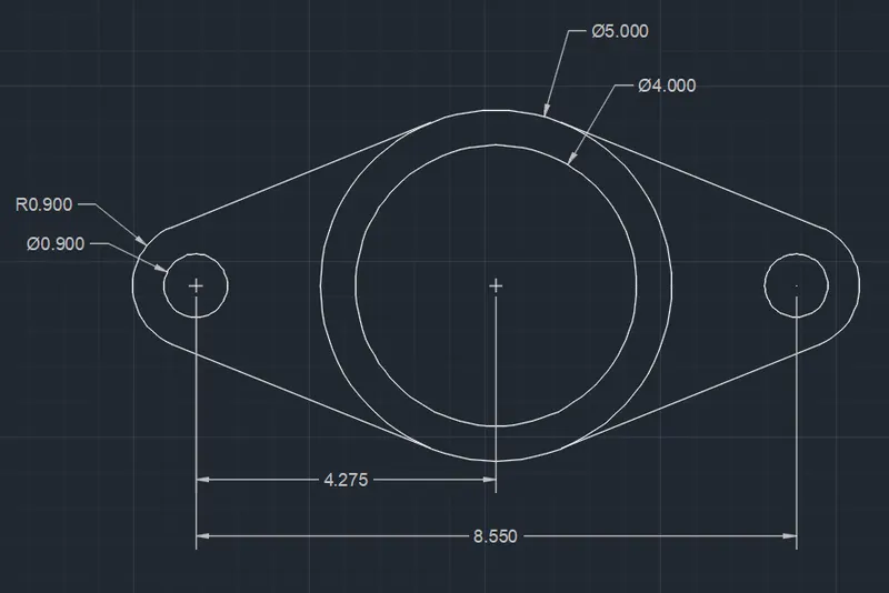
AIM: To create the given geometry using AutoCAD
INTRODUCTION: To create the geometry following tools are used:
- Circle
- Line
- Centre of
- tan of
- trim
PROCEDURE:
- First, draw the circle of dia 5 units and 4 units with the same centre
- Next, draw the circles of dia 0.9 from and radius 0.9 from 4.275 units of the first circle horizontally in both directions.
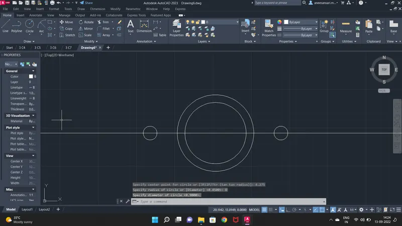
- Draw tangents using line command and tan of command to the circles as shown
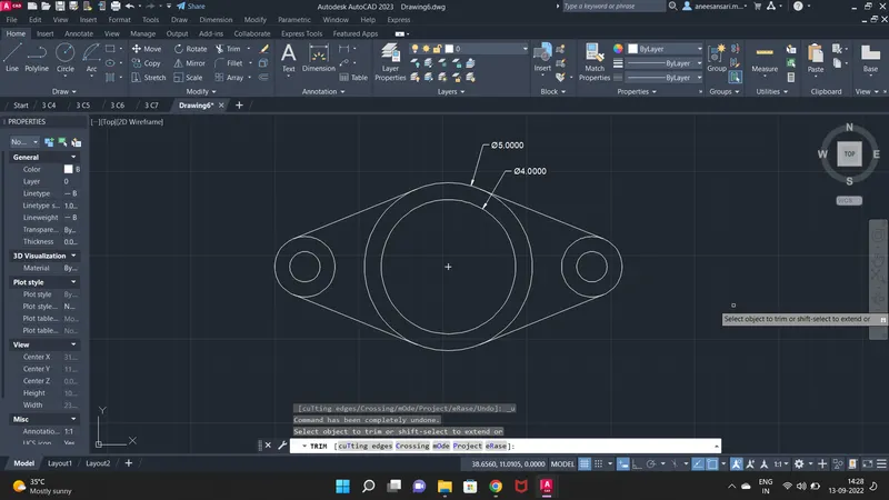
- trim unwanted curves of the circle.
- ESC
RESULT:
9
AIM: To draw the geometry like an eye mask in AUTOCAD.
INTRODUCTION: The tools used in this geometry are:
- Circle
- Fillet
- Start,end,radius curve
- trim
- end of
- centre of
PROCEDURE:
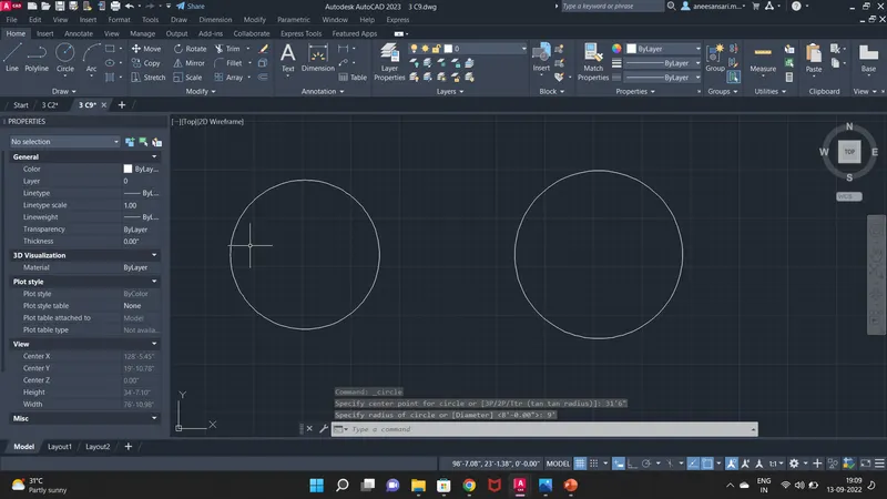
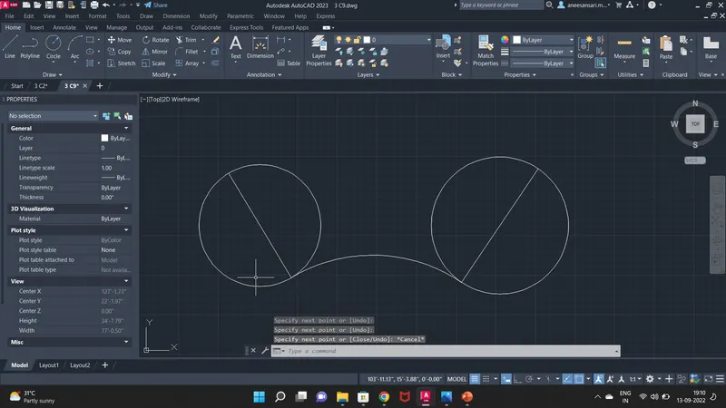
- First, draw the circle of 8 units and from the centre of the circle to 32'6" draw another circle of 9 units
- Draw the fillet to both circles at the bottom with a radius of 20'10"
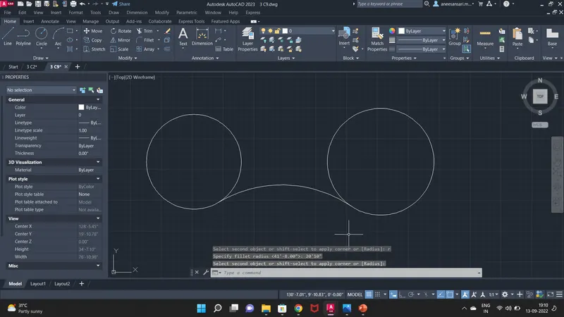
- Draw the line of intersection of the fillet to the centre in the circle like a diameter.
- Draw the start end curve, start at 9 units circle with end of snap and end at 8 units curve using end of snap with a radius of 41'8"( end snapped are ends of the dia line).
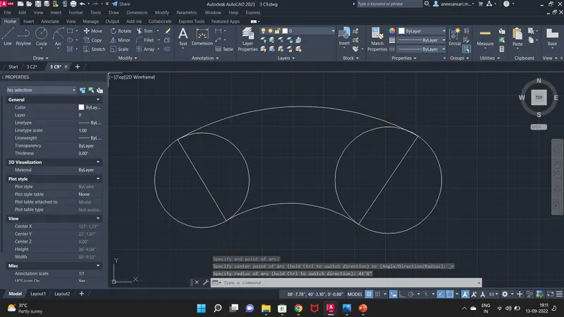
- Trim the unwanted extra curve
- ESC
RESULT: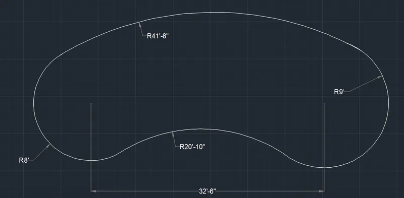
10
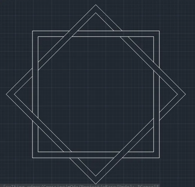
AIM: To create the given geometry in AUTOCAD
INTRODUCTION:
Commands used are
- rectangle
- rotate copy
- mid of, the centre of
- trim
PROCEDURE:
- First, draw the rectangle of equal sides i.e 100,100
- Create an offset of 10 units outwards to the rectangle
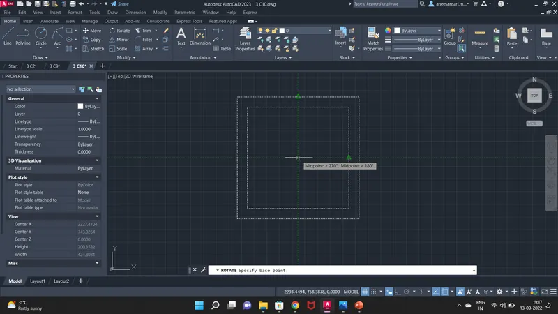
- Taking the centre of geometry of two rectangles rotate and copy them with the angle of 45 degrees
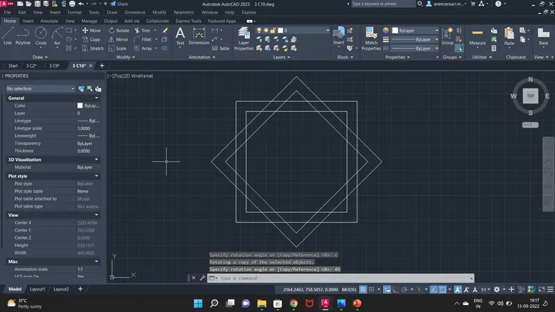
- Trim unwanted lines.
- ESC
RESULT:
11
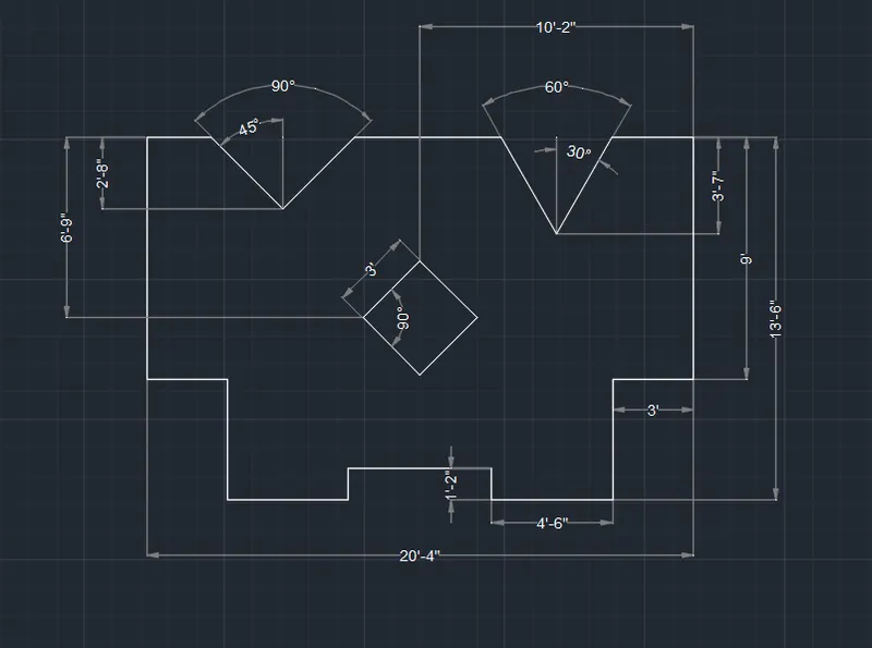
AIM: To create geometry as shown in the figure using various tools of AutoCAD
INTRODUCTION:
The tools used in this geometry are:
- polyline
- line
- break
- snaps
- mid of
- centre of
- parallel
- perpendicular
- rotate
PROCEDURE:
- First, draw the outer geometry with polyline
- Start at any random point and follow the below points in order:
- point 1: Random
- point 2: @1'2"<270
- point 3: @4'6"<180
- point 4: @4'2"<90
- point 5: @3'<180
- point 6: @13'6"<90
- point 7: @20'4"<0
- point 8: @13'6"<270
- point 9: @3'<180
- point 10: @4'2"<270
- point 11: @4'6"<180
- point 12: @1'2"<90 and then C to close the outer geometry
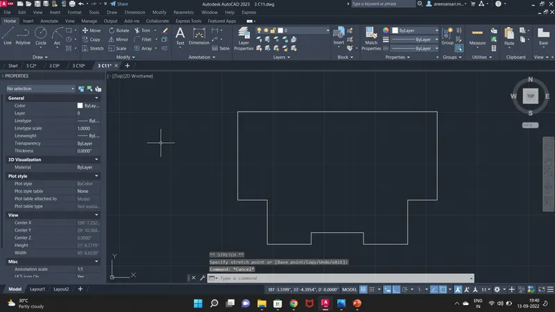
- Using the mid of the snap start line at 1'2" from the middle of geometry and draw a square of side 3' in 45 degrees angle.
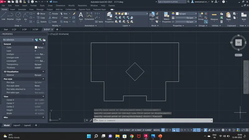
- Then break the upper line into 2
- draw the line in the middle of the left-hand line with a depth of 2'8" and for a right-hand line depth of 3'7"
- Draw rotate the lines on both sides at an angle of 45 degrees on the left and 30 degrees on right
- extend rotated lines to the border
- trim unwanted lines.
- ESC
RESULT: