Analysis & Design of RCC shear walls in the model using ETABS
Objectives of the Challenge:
- To extract values of longitudinal steel ratio, boundary element length and shear reinforcing ratio from the design results.
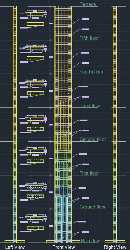
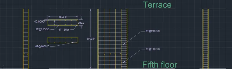
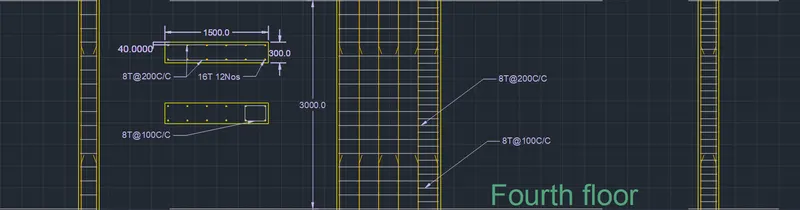
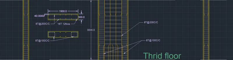
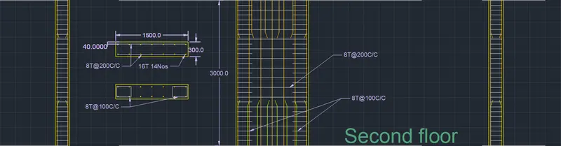
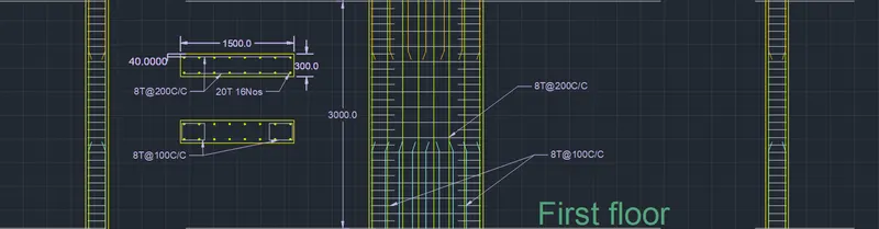
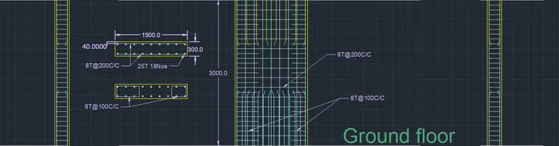
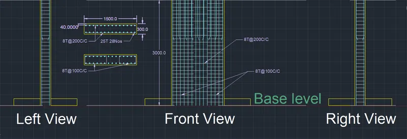
- To provide a cross-sectional steel arrangement of the shear wall from its base up to the terrace, in compliance with provisions of IS 13920 – 2016. AutoCAD application can be used for this exercise. Alternatively, it can be drawn by hand as well.
- To provide elevation drawings of the reinforcement details of the shear wall from the base up to the terrace.
Procedure:
- Import the model of the G+6 building into ETABS.
- Go to elevation 11 to design the A11 shear wall.
- No run the analysis for the entire model.
- Click on 'Shear wall design
 ' to design the reinforcement area of the shear wall.
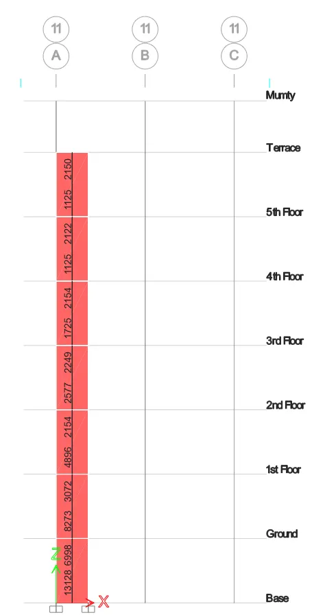
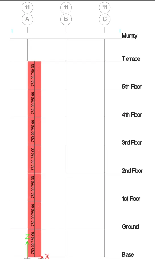
 - Check each value of the area of reinforcement in the shear wall:
- Longitudinal reinforcement or vertical reinforcement:
- Shear reinforcement or horizontal reinforcement:
- Boundary zone width:
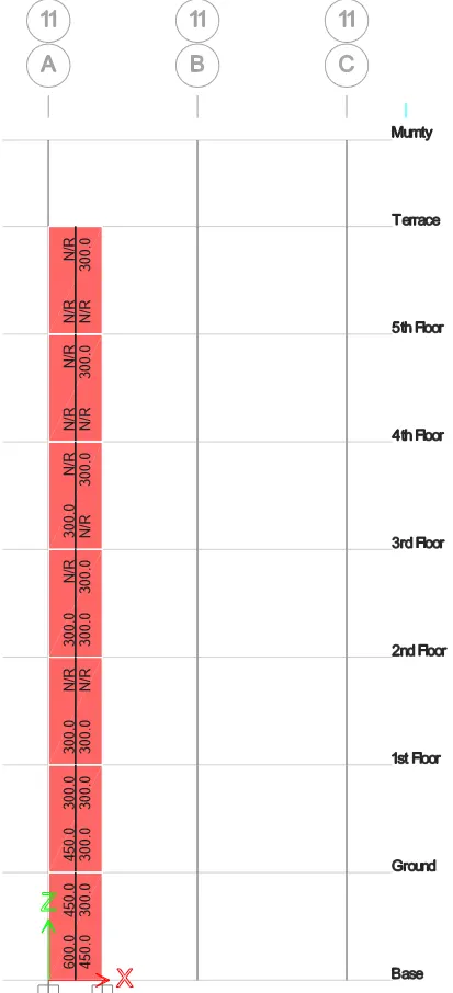
- Longitudinal reinforcement or vertical reinforcement:
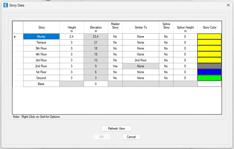
- Storey assignment table to refer to Elevation of Shear wall:
Detailing guidelines for the Shear wall:
Whichever is greater from the following, Should be drawn in RC shear wall detailing
- Minimum reinforcement for shrinkage & temperature
- Ultimate limit state design rebar requirement
- Ductility rebar requirement
- Classification of the shear wall as per IS-13920-2016 clause 10.1.4 Slender wall
hw/Lw=21000/1500=14>2 - Minimum net vertical reinforcement as per IS-13920-2016 Table-1 (iii) 2363 mm2
= 0.0025 + 0.01375 (300/1500) - Minimum vertical reinforcement within boundary element Table-1 (iii)
1440 mm2 on left (600mm width boundary element
1080 mm2 on right (450mm width boundary element
Detailed AutoCAD Sketches of Reinforcement in Shear wall A11: