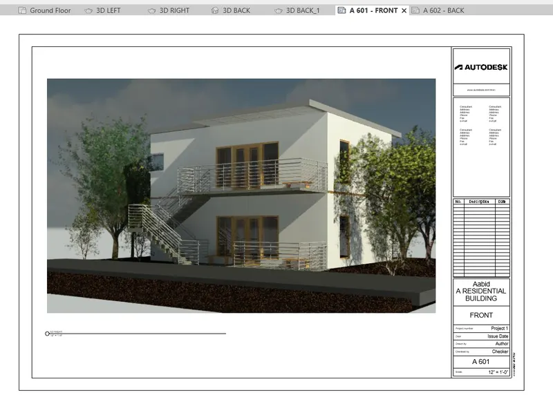
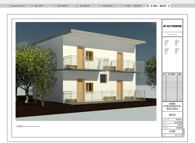
3D Creation of Celing, Roof, Architectural plan, Structural plan, Sectional view, Elevation view and Camera specific view for a house plan using REVIT
1) Based on the project saved from Week 3, proceed from the First Floor Level. Model a Ceiling from the architecture tab above the walls at the first-floor level
AIM: To create a Ceiling above the walls at the first-floor level
INTRODUCTION: The ceiling is the element of the building with comes under the roof. In Revit, It is located under the architectural and structural tab.
PROCEDURE: Open the file Challenge 3 which was saved before for the 3rd-week challenge and go to the first floor in levels.
- No under the architecture tab, we can find ROOF. click it.
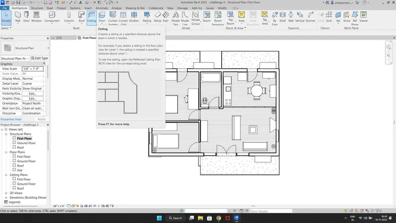
- Go to the SKETCH CEILING option to sketch it ourself
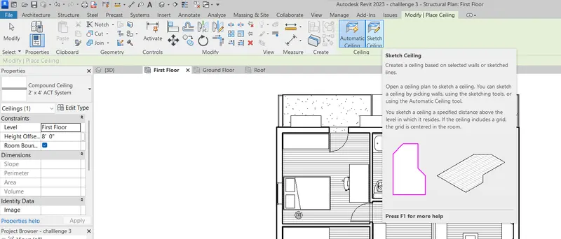
- Go to LINE in DRAW to draw the other line of the ceiling
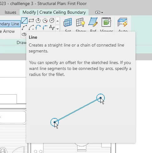
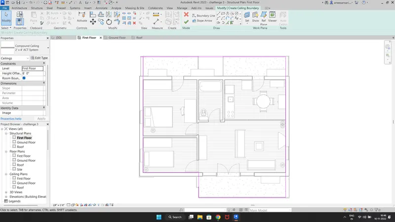
- Draw the outer line perfectly in the required locations:( No intersections are allowed)
- In PROPERTIES give the height offset from level as 10' ( floor height )
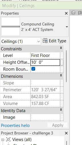
- And press enter.
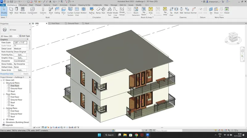
RESULT: Our required ceiling is formed:
2) Model a roof above the ceiling by selecting the footprints of the ceiling. Using the adjustment toolbars appearing on-screen adjust the roof slope to 10 degrees
AIM: To model a roof above the ceiling that have made.
INTRODUCTION: We know that a roof is needed for a building and it comes above the ceiling. For our protection, we are going to use the footprints of the ceiling to make the roof.
PROCEDURE: Go to the ROOF level to model the roof.
- Under the architecture tab, go to the ROOF. and in drop-down the open roof by footprint
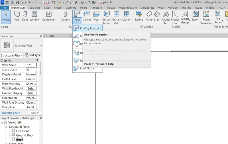
- And pic LINE from the DRAW tab to draft the boundary lines of the roof
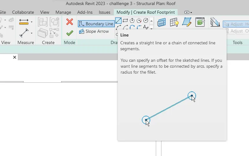
- With that line draw the exterior boundary of the slab by taking ceiling border lines as a reference.
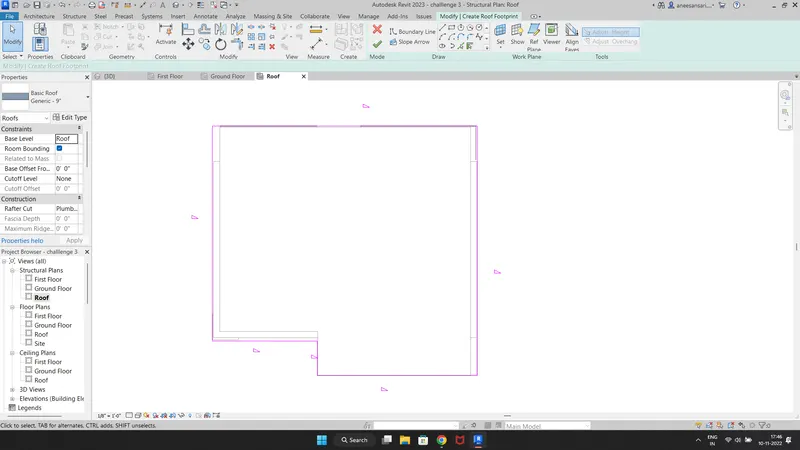
- Click enter and our roof is formed.
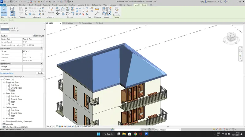
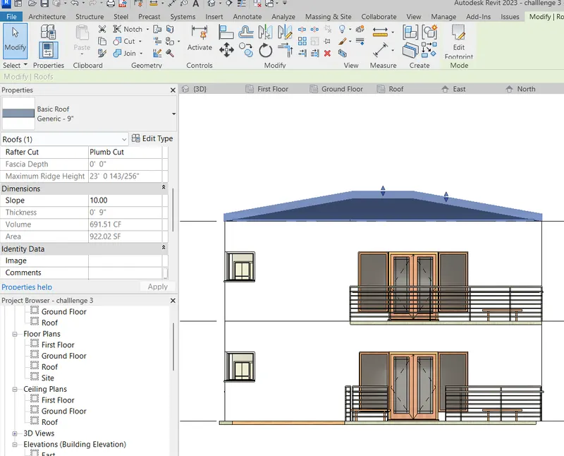
- We can see the slope adjustment tool bar on the screen when we click the roof. As per AIM, we need to make the slope of roof as 10°.
- Type UN command to open units tool bar and change the units of slope from inches to degrees °.
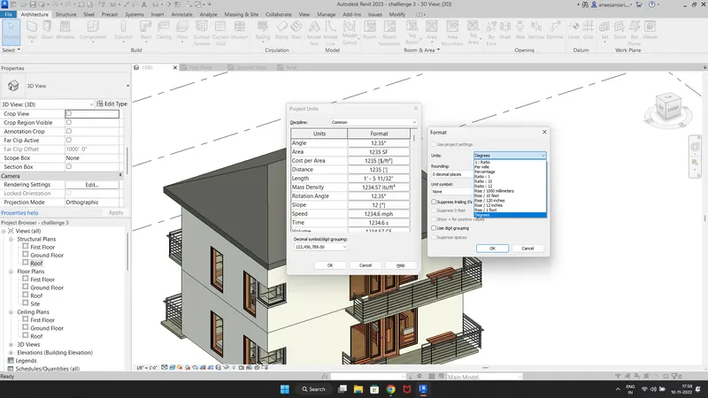
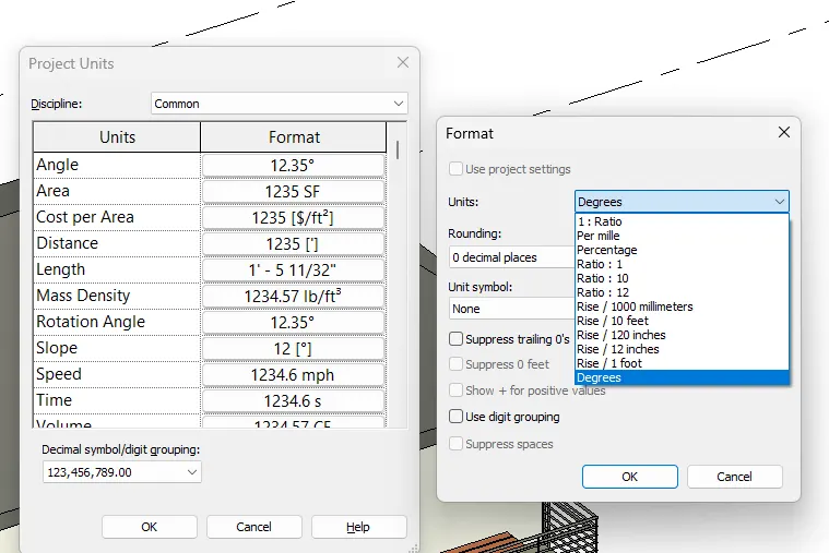
- Finally, in dimensions under properties, give the slope value as 10°.
RESULT: The roof with a slope of 10° is formed:
3) Using the file saved from weeks 2 to 4, create plan views for the ground-floor level and first-floor level including all the walls, floors, and components. Separate them into architectural and structural plans
AIM: To separate the architectural and structural plans with respective elements and components.
INTRODUCTION: We know that while we present any model we have to divide the plan and show it into two types: Architectural floor plan and structural plan. In that case, we use Revit's visual graphic feature to separate them.
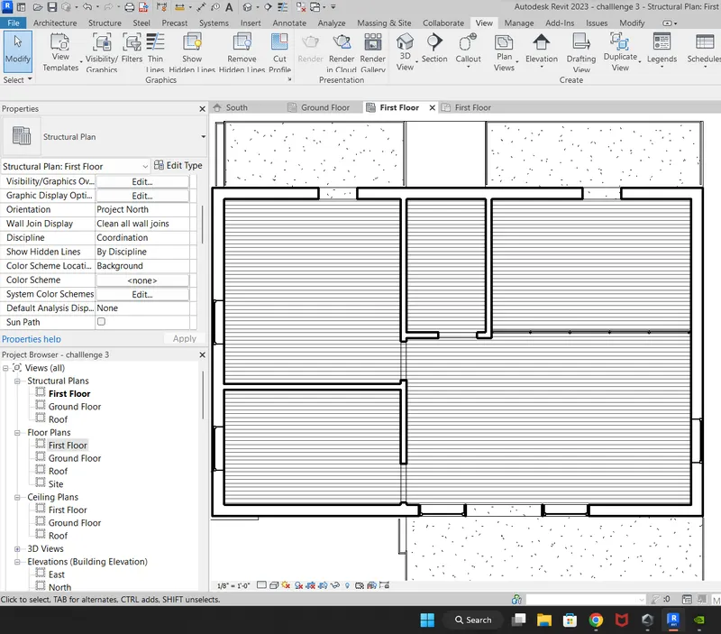
PROCEDURE: In the project browser under view we can see there are two structural plans and an architectural plan. But when we open them both of them look the same. We need to change the visibility setting of a structural plan to show only walls columns and other structural elements.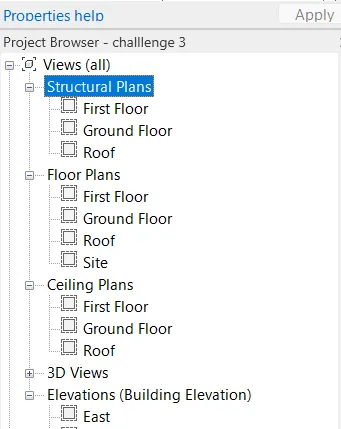
STRUCTURAL PLAN OF FIRST FLOOR: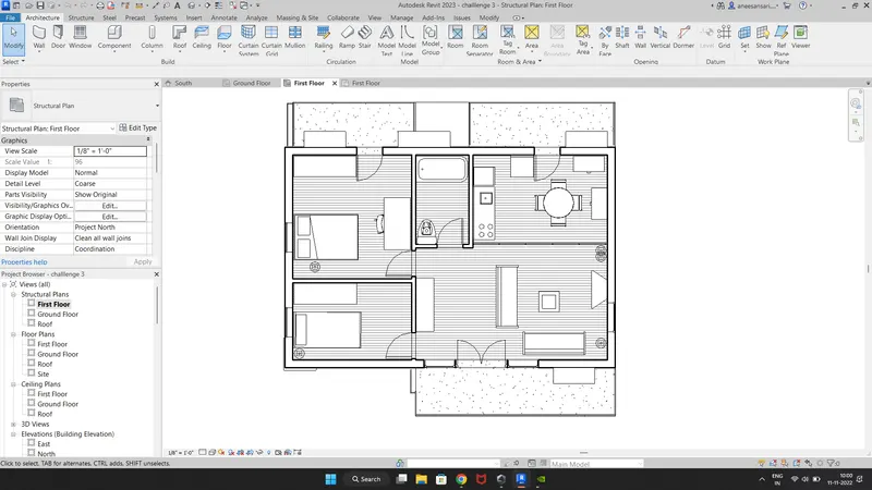
ARCHITECTURAL FLOOR PLAN OF THE FIRST FLOOR:
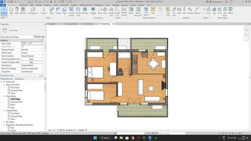
We can see both are having same components. So go to visual graphics in the view tab and remove the components which are not required in the structural plan.
Type the VG command or open Visual graphics under the View tab in the STRUCTURAL view.
Uncheck the visibilities which are not required.
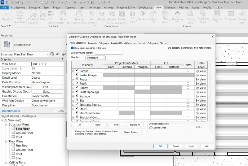
Repeat the same procedure for the Ground floor.
RESULT:
Architectural Floor plan of the first floor: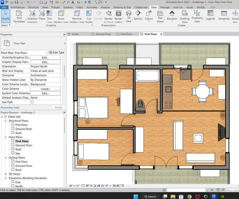
Structural plan of the first floor:
4) Using annotate toolbar add dimensions to all the walls and floors with reference to the longitudinal and transverse grids created in the project file
a. The architecture plan dimensions include details on where the components are placed within the buildings in relation to grids. Overall dimensions are sufficient for architectural plans
b. The Structure plan dimensions must include details on the position of all the walls and interior walls with reference to grids. Locate all the framing components of the building with reference to a fixed point using Structural plans
AIM: To give overall dimensions for the architectural plan AND structural plan.
INTRODUCTION: Dimensions are the most important element which help's in executing the plan. In Revit, we can find dimensions under the ANNOTATION tab
PROCEDURE:
- Go to the Ground floor plan view of Floor plan and click on the dimensions
- Select the linear dimension to add dimensions to the plan
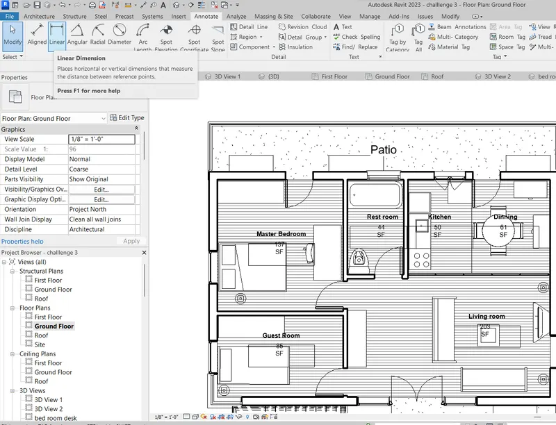
- Mark all the dimensions for the architectural plan.
- Repeat the same procedure for the Structural plan.
RESULT:
A. Architectural plan:
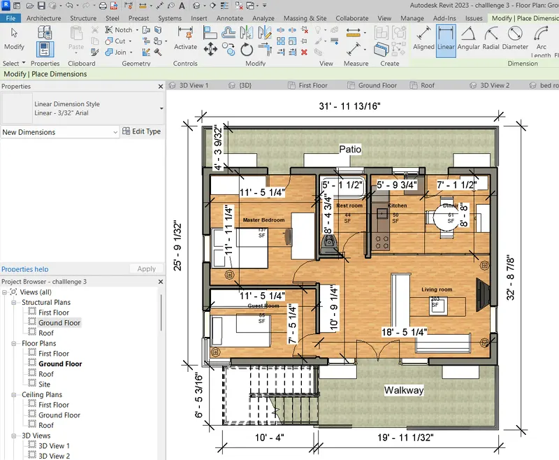
B.Structural plan: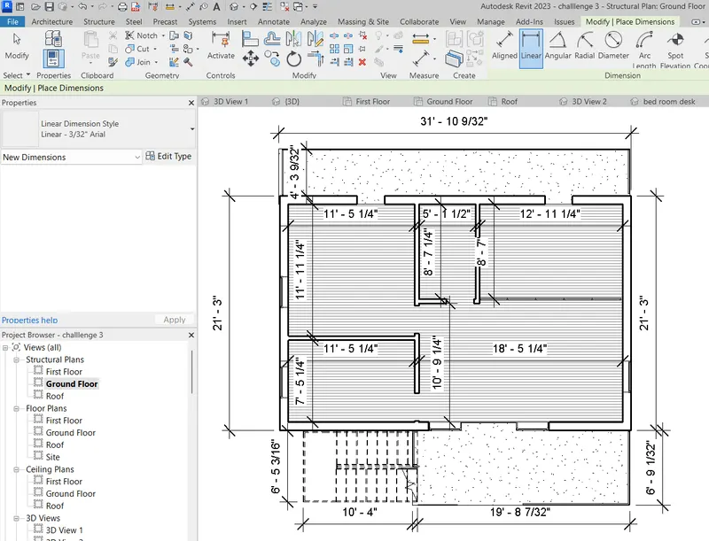
5) Create a sheet template from the view tab and adjust the parameters on the sheet to add appropriate views
AIM: To create a sheet template from the view tab and adjust the parameters on the sheet to add appropriate views.
INTRODUCTION: While providing the project to the client it should be in Sheets format, For that purpose, these sheets are made.
For that purpose, we will use the view tab to insert the sheet templates.
PROCEDURE:
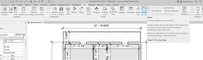
- Go to the view tab and click on SHEET.
- Click on the load
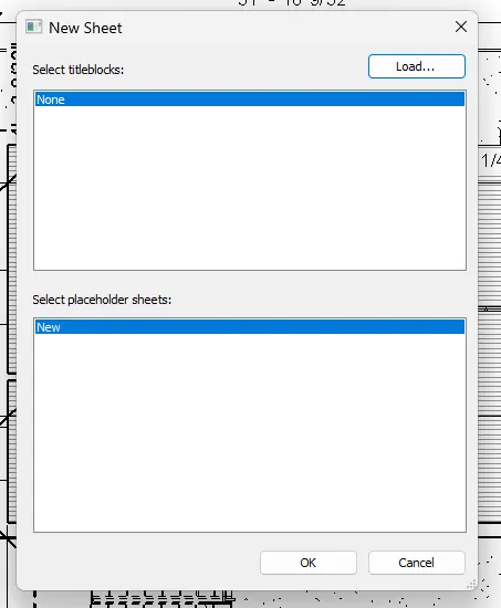
- A new menu will pop up, go to US<TITLEBLOCK< and select desired sheet
- I am loading A1 Sized sheet for this project
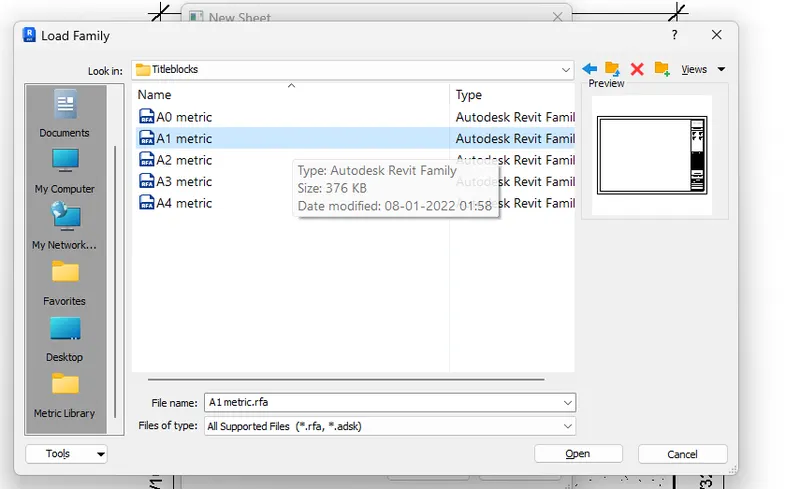
- We actually do the project in the imperial system, so open the imperial sheet from Libraries < English-imperial < title block
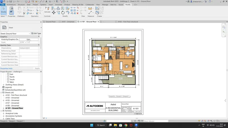
- The sheet has been opened on the Revit screen.
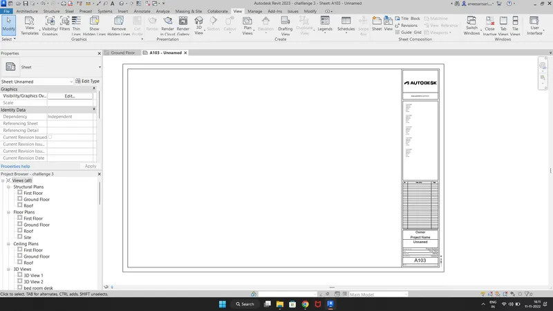
- Drag the views to the sheet and change the appropriate scales to the views
- In the manage tab, go to the project information and give the data that has been given to fill in the sheet.
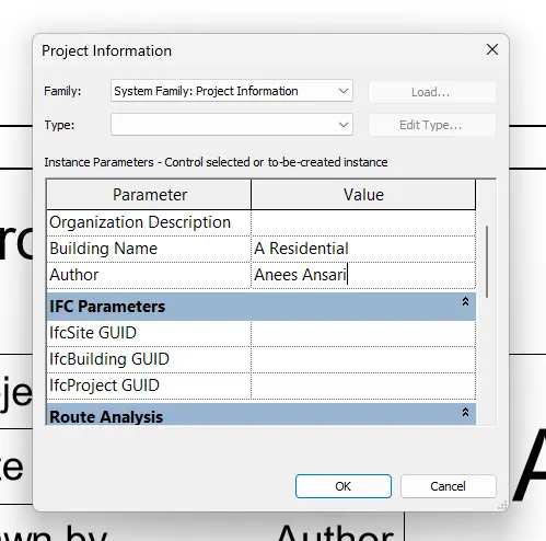
- Or else change that data on the sheet itself.
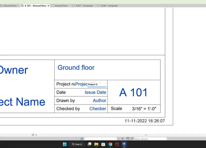
RESULT: The sheet is filled with the data and views are created:
6) Using the elevation tab create the elevation views, looking at your building from East, North, South, and West
AIM: To create the elevation views using elevation tabs.
INTRODUCTION: It is important to create elevation views to look at the side views of the building. The elevation tab from the project browser will get us that.
PROCEDURE: Go to the project browser and we can find elevation there as default. Or else we can create the elevations on our own.
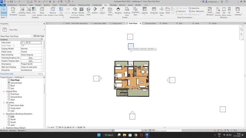
- Go to the view tab and click on the elevation option.
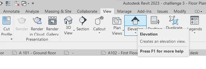
- Now place it on the EAST NORTH SOUTH and WEST directions of the building, then rename them:
- That's it.
RESULT:
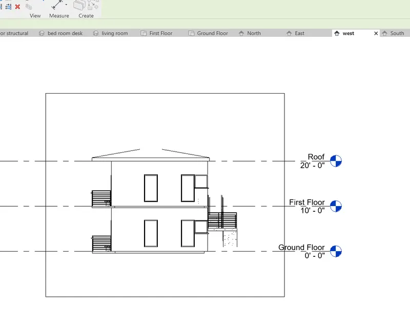
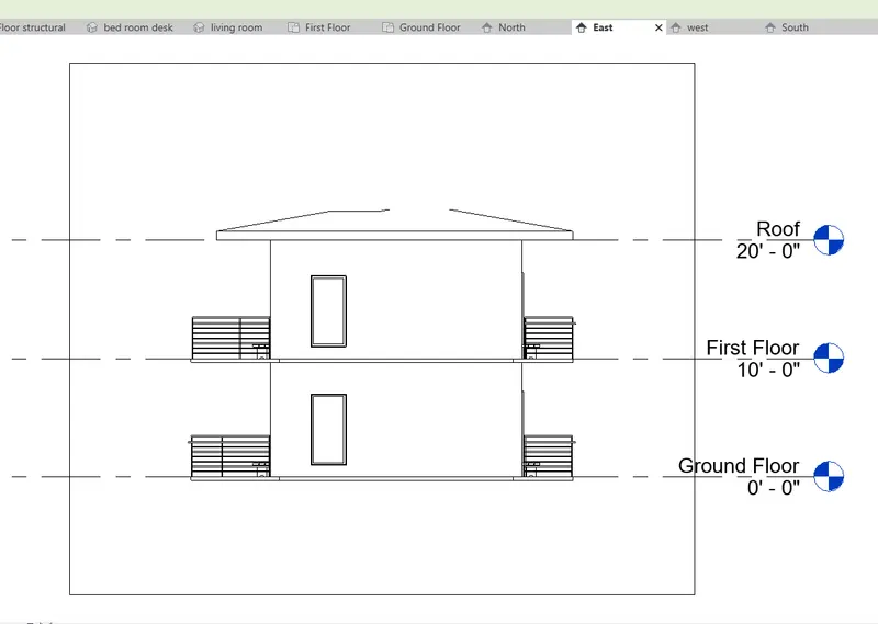
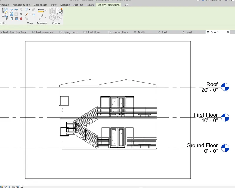
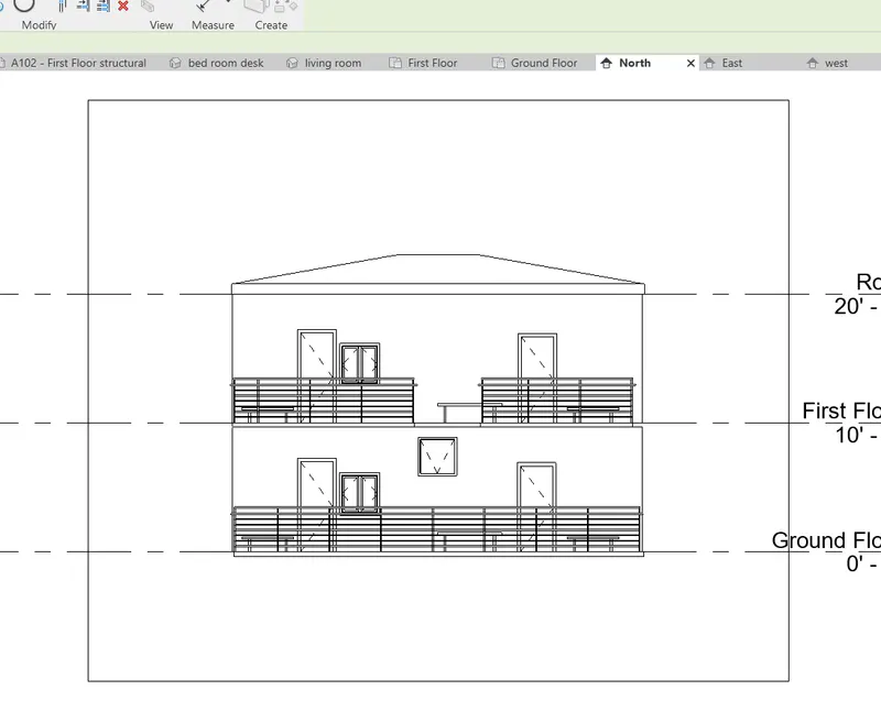
Elevations are made in 4 directions:
WEST:
EAST:
SOUTH:
NORTH:
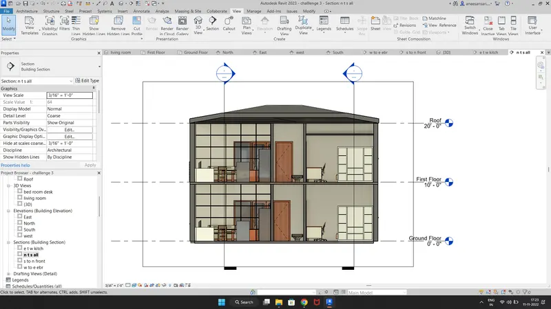
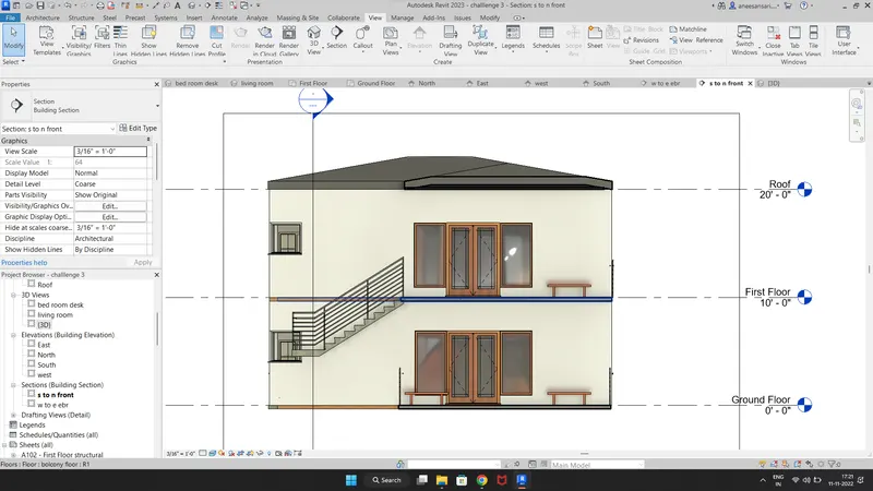
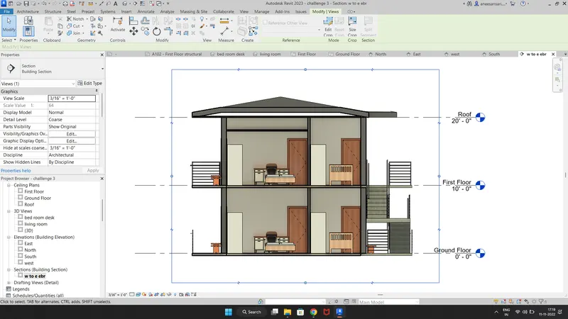
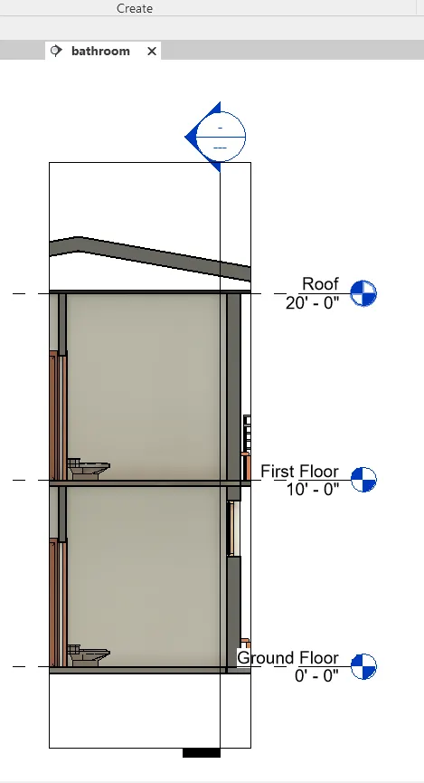
7) Produce section cut through each room either cutting across longitudinally or in a transverse direction
AIM: To cut the section through each room.
INTRODUCTION: It is important to show the sectional views of the buildings to show a clear understanding of the client that what is inside the room.
To create the sectional view, go to the view tab and use the section tool in it.
PROCEDURE:
- Go to any floor plan, and open the view tab.
- Select the section tool in it.
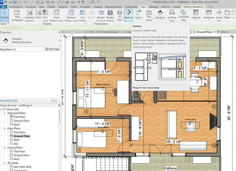
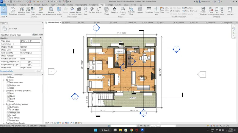
- Draw the sections at the required locations ( not only in the plan but also in elevations).
- Draw them in both transverse and longitudinal directions
- According to our convenience we can cut sections in plans or elevations:
RESULT:
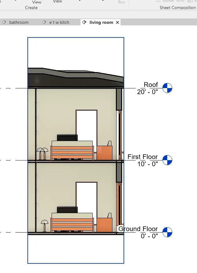
Sections that have cut down: ( THE NAME HAS ALLOTTED TO EACH SECTION IN PROJECT BROWSER)
8) Classify the views, Plan Views, Section Views, and Elevation views to either Design or Documentation category using the Properties browser.
AIM: To classify the views, Plan Views, Section Views, and Elevation views to either Design or Documentation category using the Properties browser.
INTRODUCTION: Classifiication of the types of drawings is the most important part of the project.
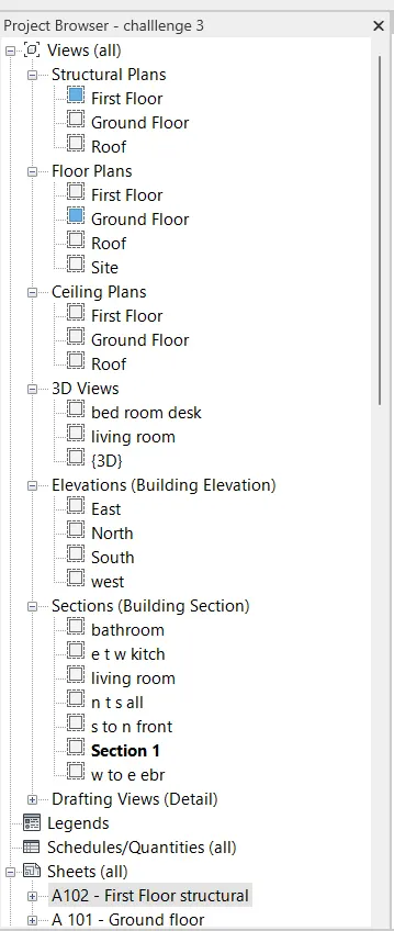
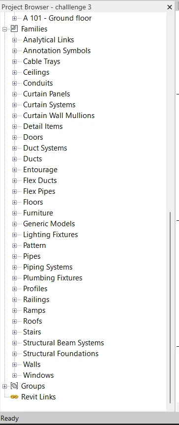
PROCEDURE: We had to do nothing here. It will be already been classified in the project browser.
RESULT:
9) Using the sheet template produced create multiple sheets as follows
a. A 101- Ground Floor Architecture Plan
b. A 102- First Floor Architecture Plan
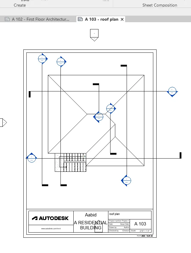
c. A 103- Roof Plan
d. S 101- Ground Floor Structural Plan
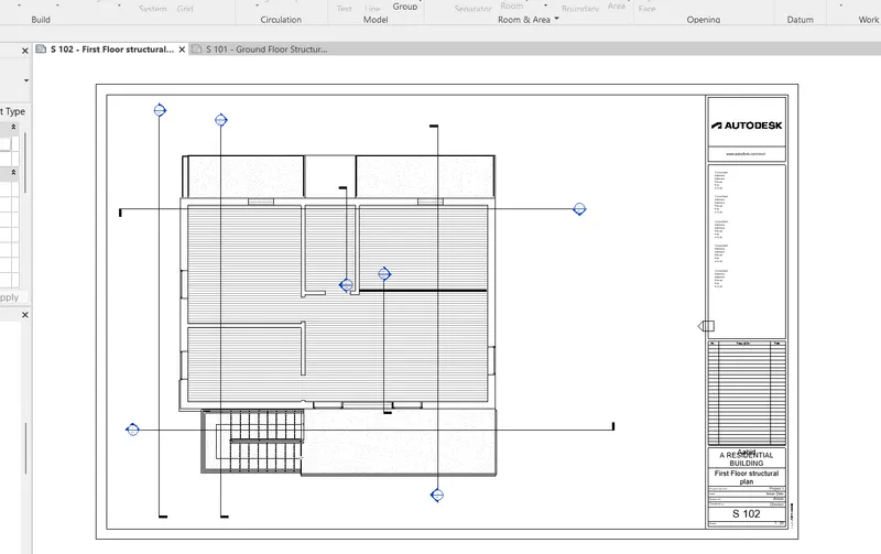
e. S 102- First Floor Structural Plan
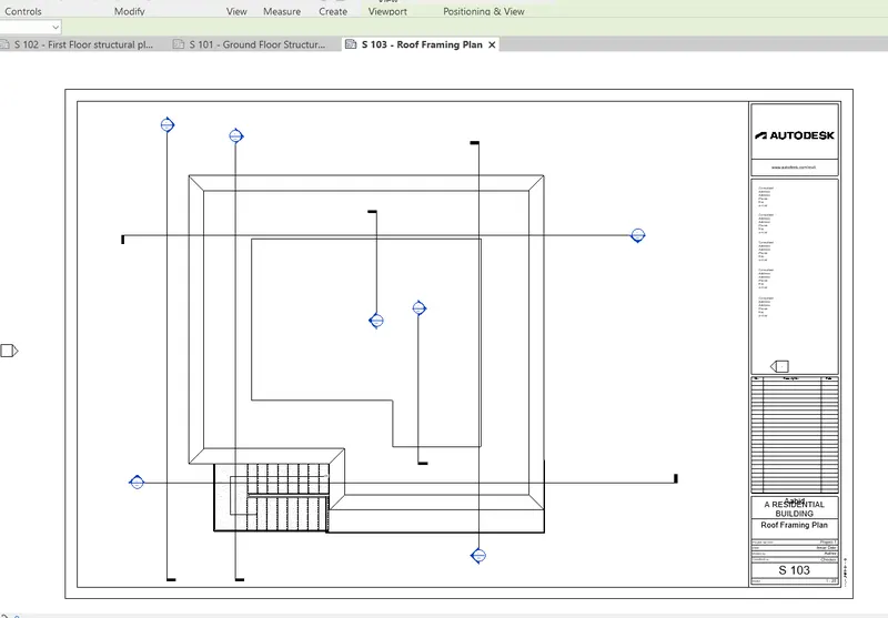
f. S 103- Roof Framing Plan
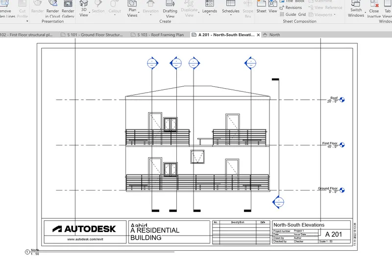
g. A-201- North-South Elevations
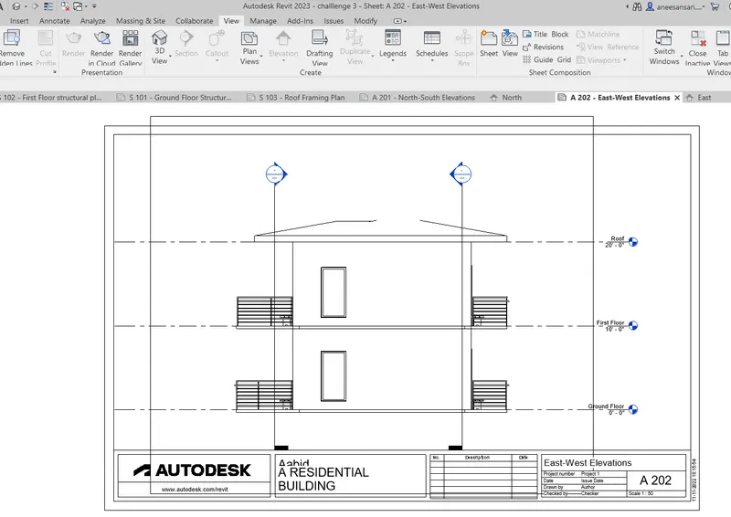
h. A-202- East-West Elevations
Add additional sheets based on the sections created in your Revit file
AIM: To create a multiple sheets template from the view tab for all the drawings.
INTRODUCTION: While providing the project to the client it should be in Sheets format, For that purpose, these sheets are made.
So, we will use the view tab to insert the sheet templates.
PROCEDURE:
- Go to the view tab and click on SHEET.
- Create a new sheet.
- Drag all the drawings that have been given in the question and change the scales to fit the sheet area.
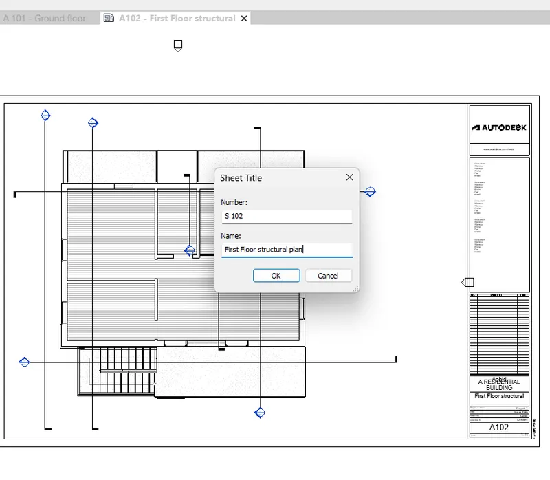
- Rename every sheet as per the required names and drawing numbers.
- a. A 101- Ground Floor Architecture Plan
b. A 102- First Floor Architecture Plan
c. A 103- Roof Plan
d. S 101- Ground Floor Structural Plan
e. S 102- First Floor Structural Plan
f. S 103- Roof Framing Plan
g. A-201- North-South Elevations
h. A-202- East-West Elevations
- a. A 101- Ground Floor Architecture Plan
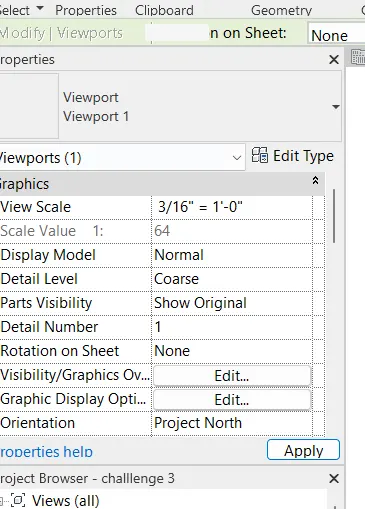
- Give appropriate scale to fit in:
- Drag the sections to new sheets and name them accordingly.
RESULT:
a. A 101- Ground Floor Architecture Plan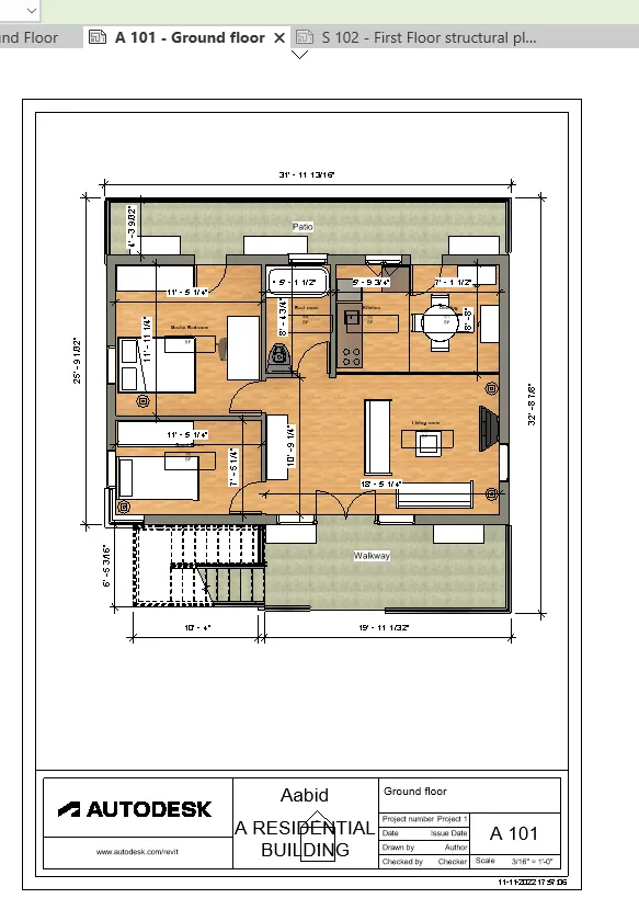
A 102- First Floor Architecture Plan
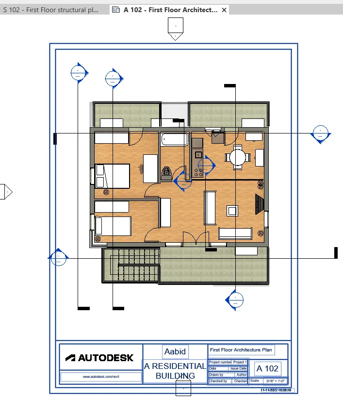
c. A 103- Roof Plan
d. S 101- Ground Floor Structural Plan:

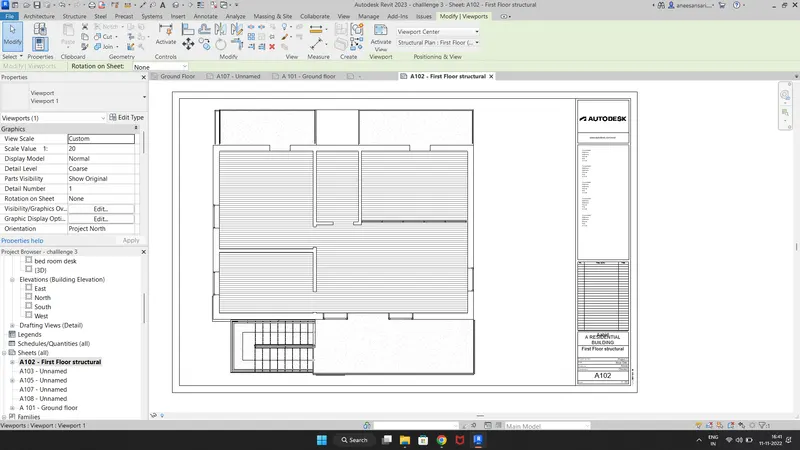
e. S 102- First Floor Structural Plan:
f. S 103- Roof Framing Plan:
g. A-201- North-South Elevations:
h. A-202- East-West Elevations:
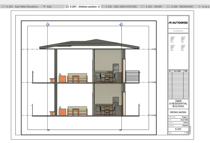
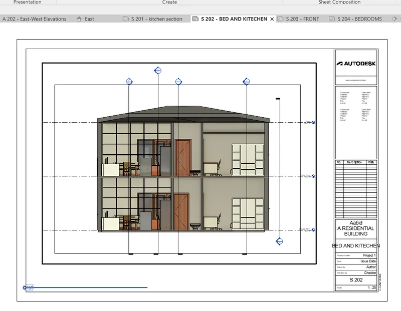
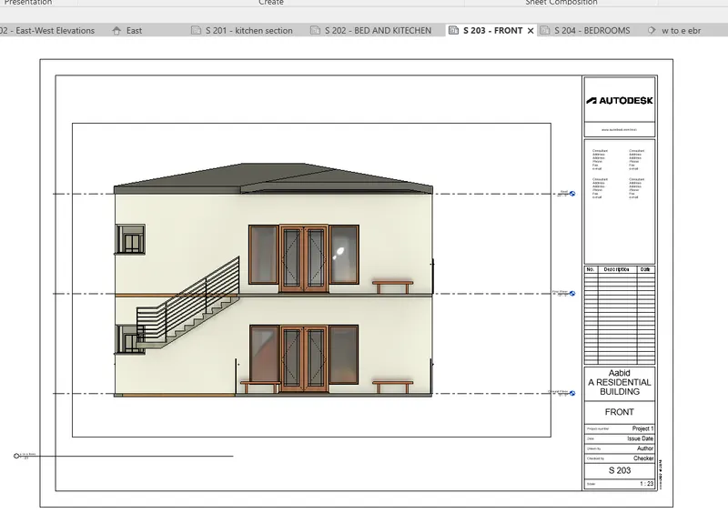
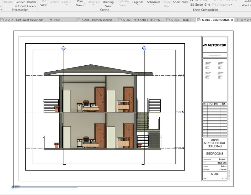
And we can create Sectional views:
S 201 kitchen section
S 202 BED AND KITECHEN
S 203 FRONT
S 204 BEDROOMS
10) Create a camera-specific view or a 3D view in each room ( living, dining, bedroom). Based on the views create a new set of sheets starting A-501 (you can add as many sheets after, 502, 503.. n)to place the 3D view images. Produce the sheets as a part of project drafting.
AIM: To create a camera-specific view of each room and produce sheets on it.
INTRODUCTION: At the final submission of the project we should show what's inside the building and the views should be aesthetic.
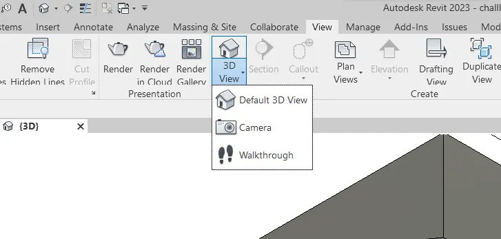
In that case, we use CAMERA under the 3d drop-down of the view tab.
PROCEDURE:
Go to the camera in the view tab:
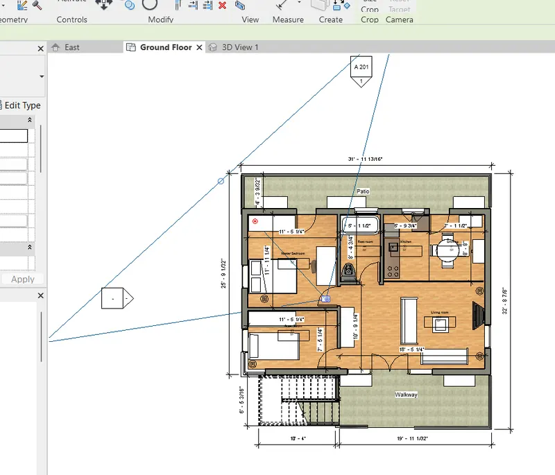
Place them in the desired location:
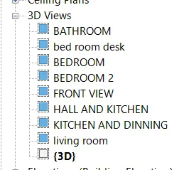
Save every camera in 3d views:
Drag the camera views to the sheets and rename the sheets:
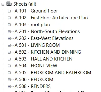
(A501- A 506 are camera sheets)
RESULT:
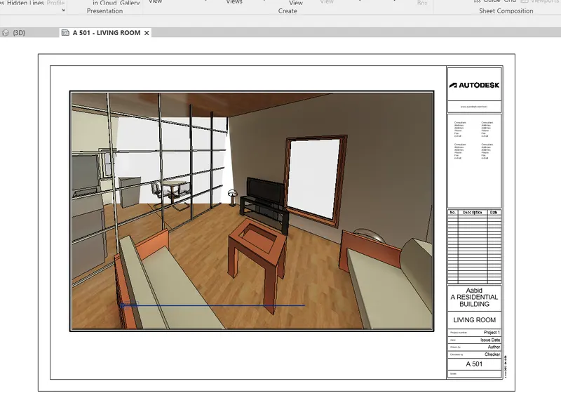
A 501 - LIVING ROOM
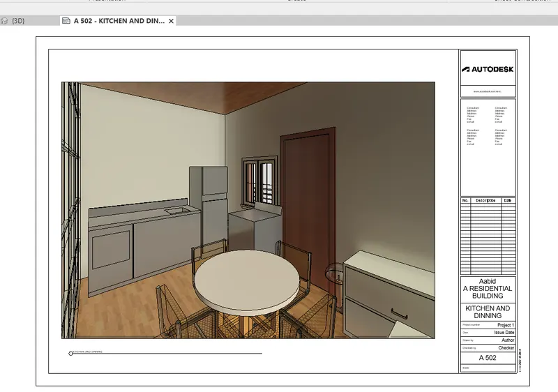
A 502 - KITCHEN AND DINNING
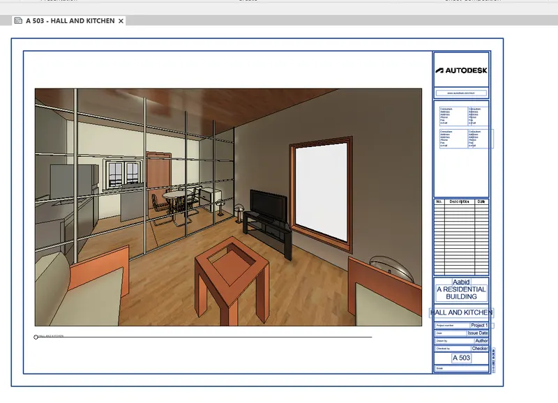
A 503 - HALL AND KITCHEN
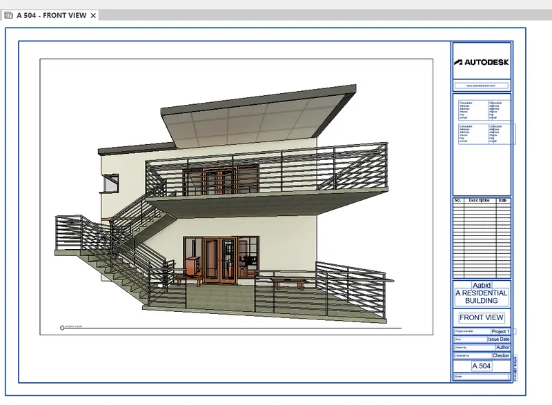
A 504 - FRONT VIEW
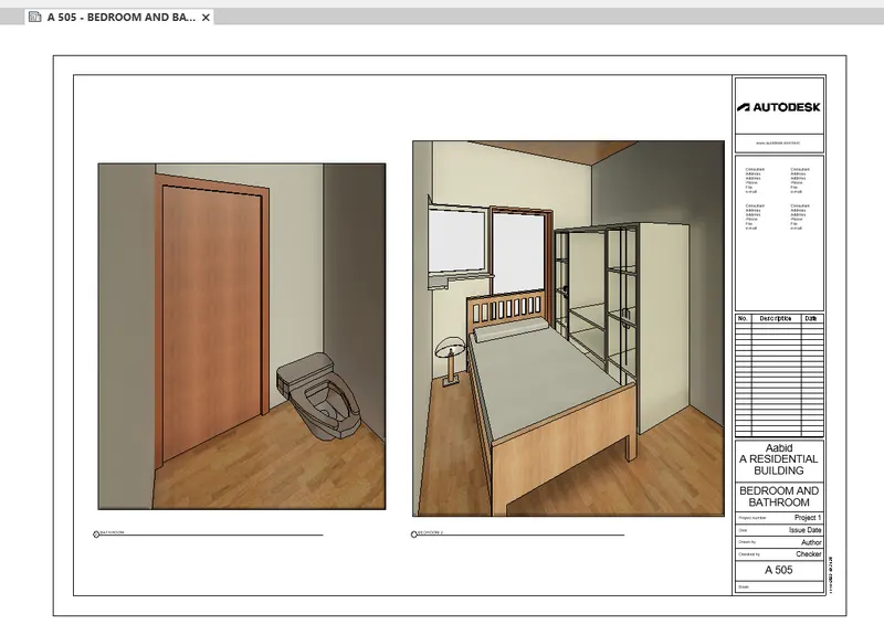
A 505 - BEDROOM AND BATHROOM
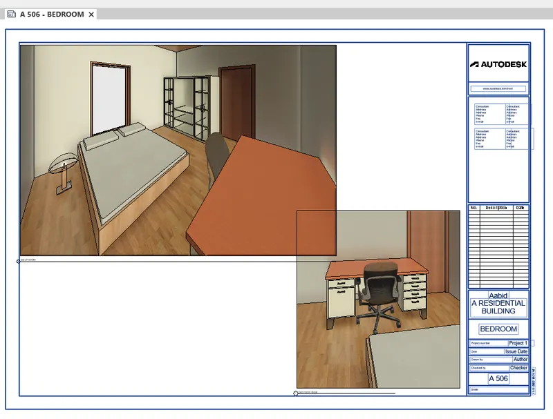
A 506 - BEDROOM
A 508 - RENDERS
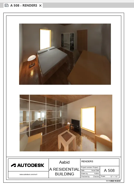
FINAL 3D VIEW OF THE PROJECT: