Reinforcement Detailing of Beams from ETABS output
Objectives of the Challenge:
- To know the design of RC beam using ETABS analysis
- To know the basics of Beam reinforcement detailing with respect to primary standards
- To ensure the ductility reinforcement required by IS-13920-2016 has been satisfied in the ETABS design
Detailing rule of any Reinforced concrete member:
| 1 | Minimum reinforcement for shrinkage & temperature | Whichever is greater, Should be drawn in RC beam detailing |
| 2 | Reinforcement required for limiting crack-width | |
| 3 | Ultimate limit state design rebar requirement | |
| 4 | Ductility rebar requirement |
- Minimum longitudinal reinforcement as per IS-13920-2016 clause 6.2.1 As = 360 mm^2
- Minimum shear or transverse reinforcement as per IS-456-2000 clause 26.5.1.6 ( Assuming 1000mm spacing in the formula) Asv = 332 mm^2
- Development length as per IS-456-2000 clause 23.2.1 Ld = 41 x diameter of the bar
Go to ETABS software and open the File which has attracted to the link.
Go to the first-floor plan. In this, we have to design the Beams which are marked.
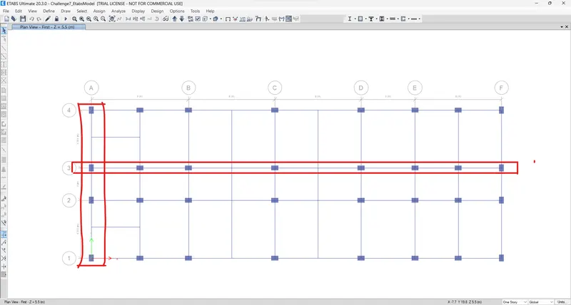
Analyze the model and click on the  (concrete frame design) symbol to design the concrete detailing for all the frames
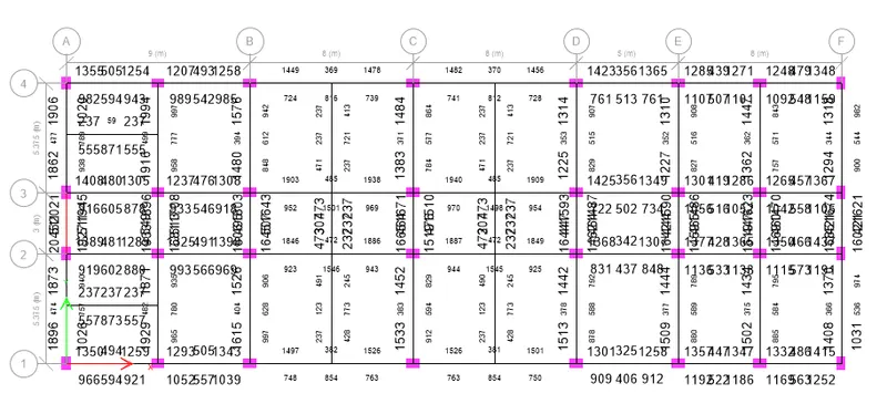
These are the details of longitudinal reinforcement. Now we have to look into the details of shear reinforcement.
Go to the drop-down of (concrete frame design) :
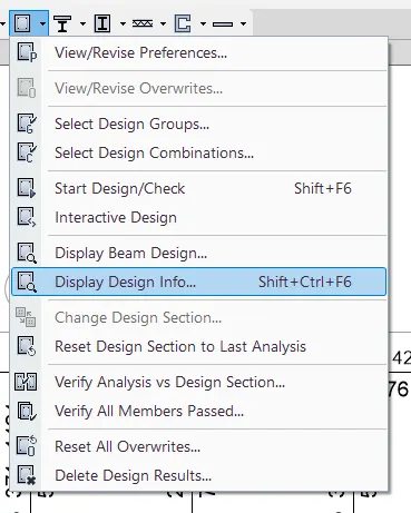
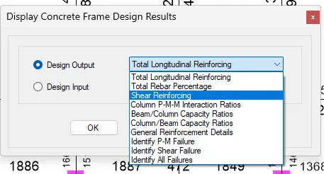
Go to display Design info and change longitudinal Reinforcement to shear reinforcement.
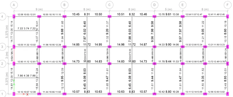
_________________________________________________________________________________________________________________________________________
Question: Provide reasons for the failure of the middle span along grid A. What are the possible ways this issue can be resolved?
Ans:
We can notice this middle span is over-stressed:
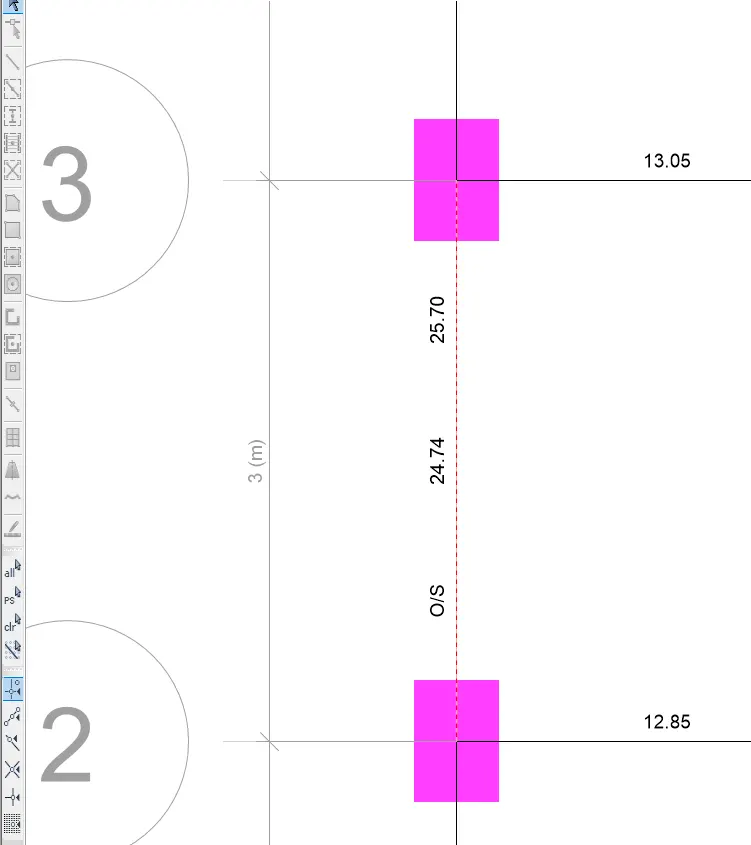
The stress is beyond the relievable value that's why reinforcement is impossible to calculate.
In the shear details, it shows:

Where torsion is also very minimum is 0.0014 kN-m due to the high design shear is 414.577KN
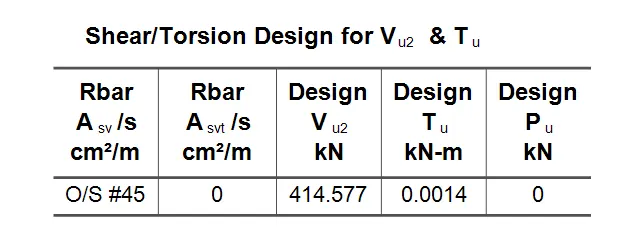
Suggestions to make it past in the design:
We know that, Shear stress= Load/Area.
- We have to reduce the loading.
- We have to increase the area to decrease the design shear.
- The shear capacity of concrete varies with respect to the grade of concrete. So instead of using the default M25 concrete used for the entire model, if we use some higher grade for this respective beam then the issue will be resolved and can pass in the design shear.
________________________________________________________________________________________________________________________________________________________________________________________________________________________________________________________________________________________________________________________________________________________________________________________________________________________________________________________________________________________________________________________________________________________________________________
Longitudinal Reinforcement of Beam at Grid-A from ETABS (mm^2):
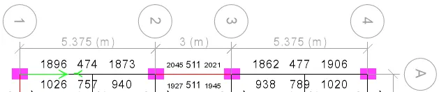
Shear Reinforcement of Beam at Grid-A from ETABS (cm2/ 1000 mm):
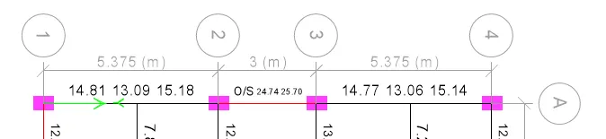
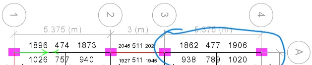
Longitudinal Reinforcement of Beam at Grid-3 from ETABS (mm^2):

Shear Reinforcement of Beam at Grid-3 from ETABS (cm2/ 1000 mm):

Additional Reinforcement guidelines from IS 13920 2016:
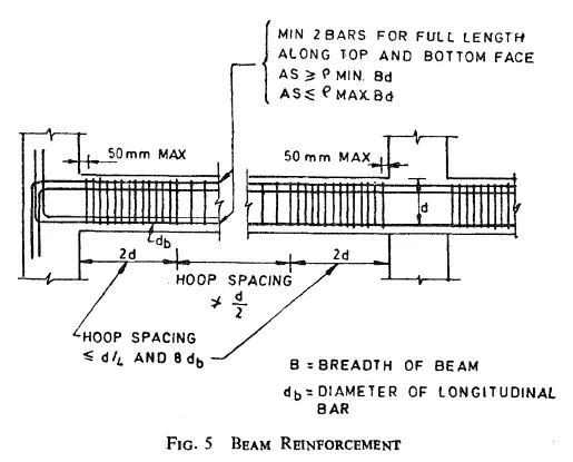
DETAILED AUTO CAD SKETCH OF BEAM AT GRID-A:

DETAILED AUTO CAD SKETCH OF BEAM AT GRID-3:



________________________________________________________________________________________________________________________________________________________________________________________________________________________________________________________________________________________________________________________________________________________________________________________________________________________________________________________________________________________________________________________________________________________________________________
TO CALCULATE THE MAXIMUM SHEAR FORCE IN ANY ONE OF THE SPANS IN BOTH THE CONTINUOUS BEAMS:
LET'S TAKE THIS SPAN:
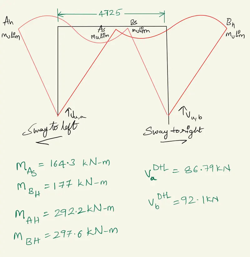
as per clause 6.3.3 (b) in IS 13920 – 2016"
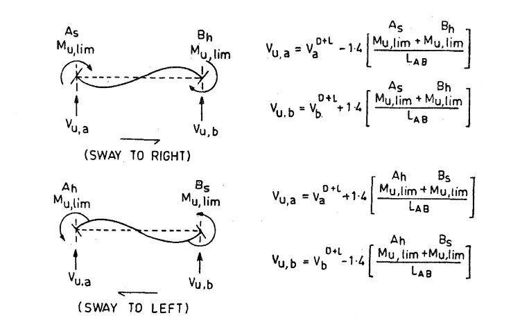
Sway to right:
Vu,a=84.7KN
Vu,b=86.9KN
Sway to left:
Vu,a=92.3KN
Vu,b=91.9KN
Comparing the value provided by ETABS with the value calculated:
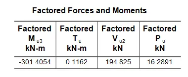
HENCE SHEAR REBARS IN DRAWING ARE OKAY AS PER IS 13920 CODE GUIDELINES.