Project 1_Comparative study of different storey buildings for Seismic forces
AIM: To model and analyze the different-storey buildings and to do a comparative study for Seismic forces.
OBJECTIVES OF THE PROJECT:
- To know how to extract different seismic responses for a structure.
- To understand how to easily alter certain properties in an ETABS model.
- To learn the factors influencing the dynamic characteristics of a building.
- To know the factors influencing the Time period of building.
- To know the factors influencing the Mode shape of the building.
INTRODUCTION:
Strutural configuration plays a vital role in how the building responds to seismic behaviour. In this project, we are going to know about the different responses of building with different structural configurations for seismic forces.
In this project, the given data is:
Structural Element size:
- Beam: 300 X 400 mm
- Columns: 500 X 500 mm, 400 X 400mm, 550 X 300mm, 300 X 550mm, 600 X 600mm, 800 X 800mm (Varies)
- Slab: 150 mm thick
Material Properties:
- Grade of concrete: M30
- Grade of steel Reinforcement Bars: Fe 415
Loading
- Dead Load on beams from infill wall: 10 kN/m
- Live load on the floor : 3 kN/m2 (What is the seismic mass?)
Buildings are assumed to be pinned at the base.
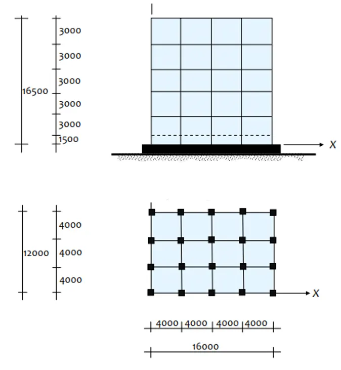
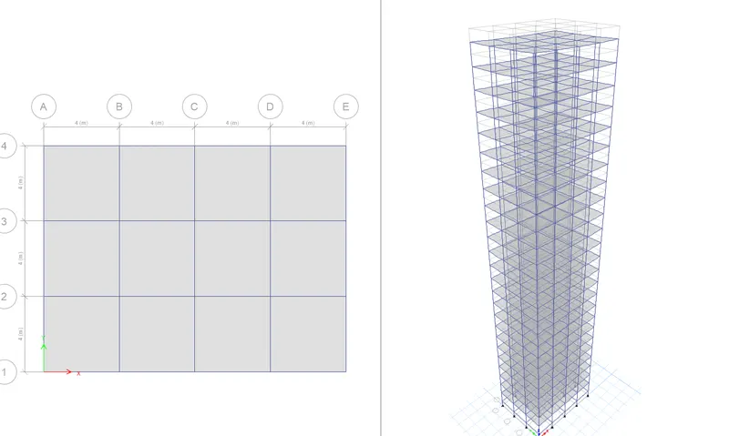
Five-storey benchmark Building: Elevation and plan of benchmark building showing the structural moment frame grid (All dimensions are in mm).
In this project, we have to model 9 buildings and compare them. Specifications of those 9 buildings are mentioned in the table below:
| Building | Description | Number of storeys | Number of bays | Column Dimensions (mm x mm) | |
| X-direction | Y-direction | ||||
| A | 2 storey building | 2 | 4 | 3 | 400X400 |
| B | Benchmark 5-storey building | 5 | 4 | 3 | 400X400 |
| C | Benchmark building with rectangular column orientation along the X direction | 5 | 4 | 3 | 550X300 |
| D | Benchmark building with rectangular column orientation along the Y direction | 5 | 4 | 3 | 300X550 |
| E | A 10-storey building with varying column sizes along the building height | 10 | 4 | 3 | Upper 5 storeys: 400X400 |
| Bottom 5 storeys: 600X600 | |||||
| F | 10-storey building | 10 | 4 | 3 | 600X600 |
| G | A 25-storey building with varying column sizes along the building height | 25 | 4 | 3 | Upper 5 storeys: 400X400 |
| Middle 10 storeys: 600X600 | |||||
| Bottom 10 storeys:800X800 | |||||
| H | 25-storey building | 25 | 4 | 3 | 800X800 |
| J | A 25-storey building with imposed mass 10% larger than building H | 25 | 4 | 3 | 800X800 |
| K | A 25-storey building with imposed mass 20% larger than building H | 25 | 4 | 3 | 800X800 |
| Note: | The Bay length in each plan direction is 4m (centre to centre). | ||||
| All columns at each storey are of the same size. | |||||
| All beams in all buildings are of the same size(300 X 400mm) | |||||
And we have to investigate the effects listed below:
Effect of stiffness on T: Compare the fundamental natural periods of building E & F as G & H. why is the mare a marginal or significant difference in the fundamental natural periods?
Effect of mass on T: Compare the fundamental natural periods of buildings H, J and K. Have the buildings become more flexible or stiff due to change in mass?
Effect of Building Height on T: How do the fundamental natural periods of buildings A, B, F and H change with a change in building height?
Effect of Column Orientation on T: How do the fundamental natural periods of Buildings B, C and D change with a change in column orientation?
Effect of Flexural Stiffness of Structural Elements on mode shapes: Compare the fundamental mode shape of building B in two situations when the flexural stiffness of beams relative to that of adjoining columns is very small versus when it is large.
Effect of Axial Stiffness of Vertical Members on mode shapes: Compare the fundamental mode shape of building H in two situations when the axial cross-sectional area of columns is very small versus when it is large.
Effect of Degree of Fixity at column bases on mode shapes: Compare the fundamental mode shape of building B in two situations when the base of columns is pinned versus when it is fixed.
PROCEDURE:
Open ETABS software:
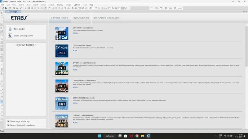
Select New model
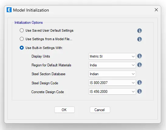
Give model information:
- Use built-in settings with:
- Metric SI
- Indian
- Indian
- IS 800:2007
- IS 456:2000
Then set the template as required:
FOR BUILDING A:
Every building has 4 bays on the X-axis and 3 bays on the Y-axis.
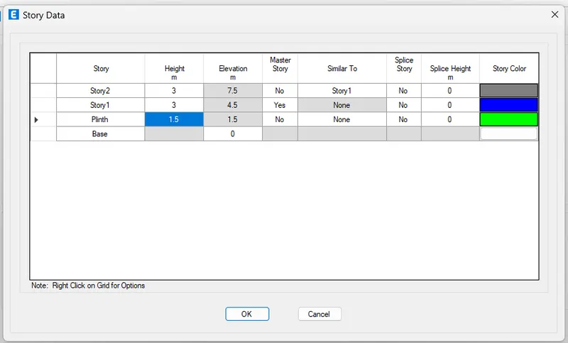
For Building A there are only 2 Storeys
Add materials :
Provide M30 concrete and HYSD 415 rebars.
Add section properties:
Beams: 300 X 400 mm
Columns: 400 X 400 mm
Slab: 150 mm
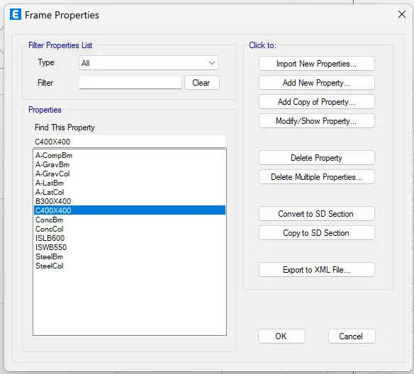
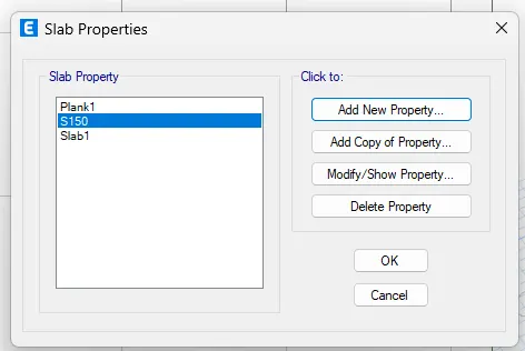
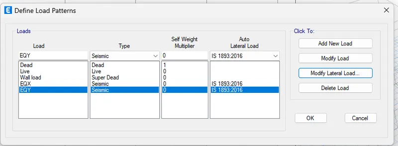
Now its time to add load patterns:
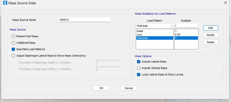
Provide mass source and edit similar to the previous model (100% dead load, 25% live load, 100% Wall load)
Create load combinations for concrete design with a user-modified option.
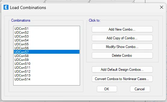
The definition part is done. Now go for modelling:
Columns: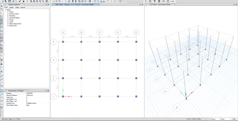
Beams: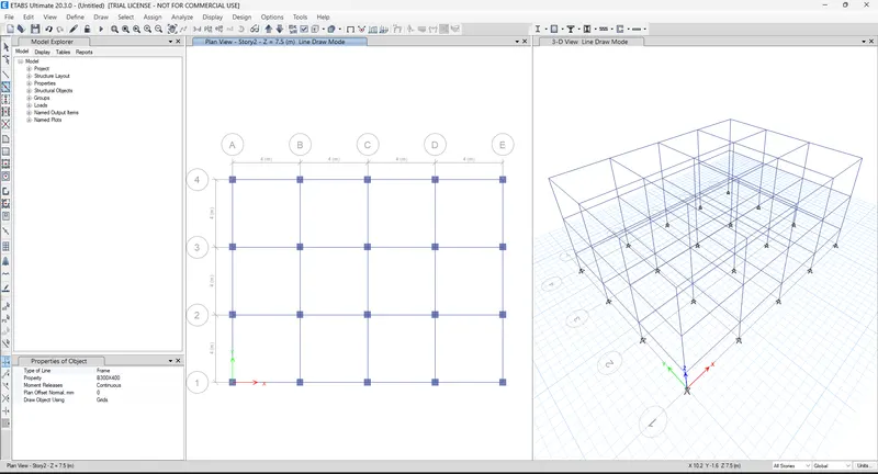
Slab: ( only for storeys )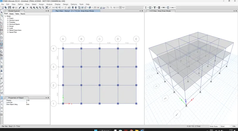
Assign loads to the model now:
Assign wall load as 10KN/m^2 to the beams: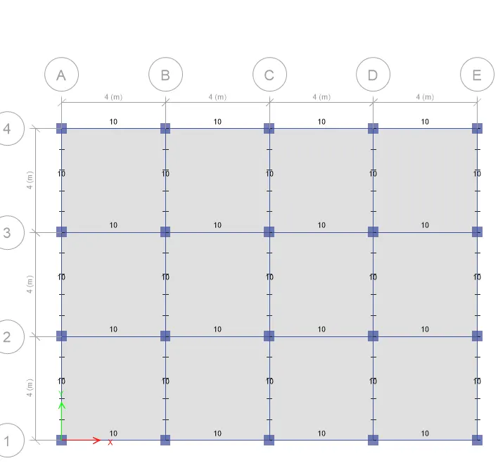
Assign a live load of 3KN/m^2 to all the slabs:
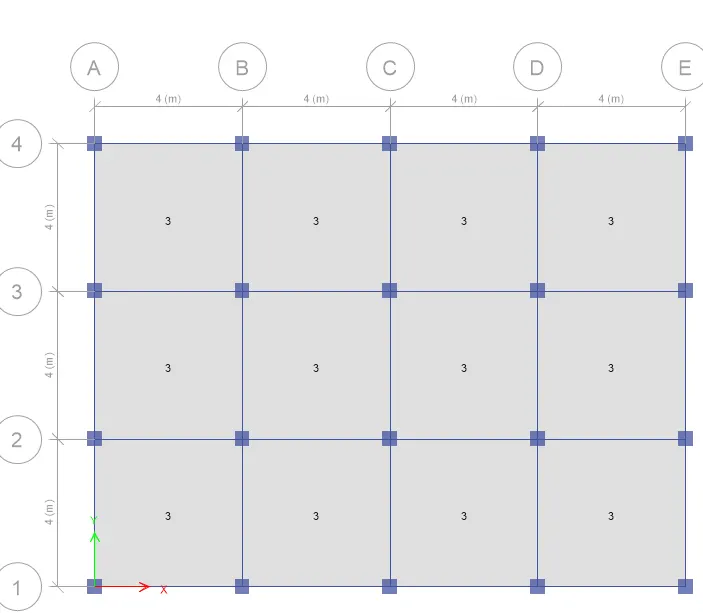
Assign diaphragm to all the slabs:
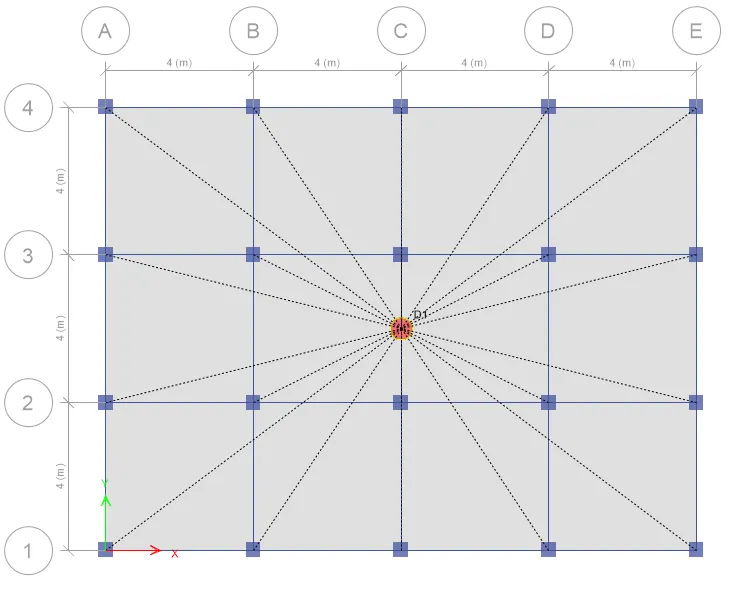
That's all about modelling and assigning! Now we can run the analysis by just selecting the F5 button.
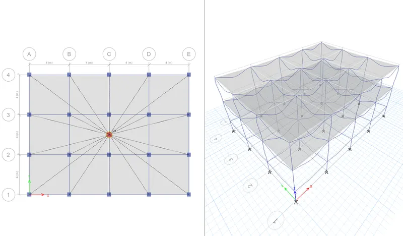
Save building as BUILDING A
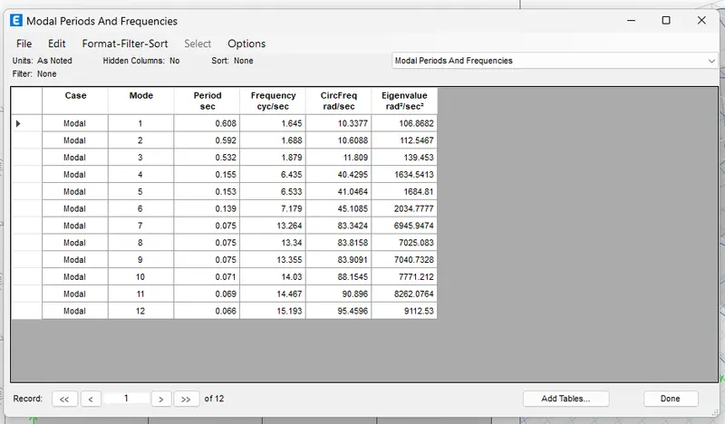
MODAL RESPONSE FOR BUILDING A:
FOR BUILDING B:
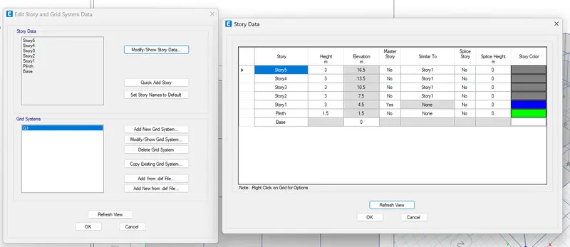
So go to Edit < story data and 3 more storeys on storey 2 by replicating it as storey 1.
Run Analysis: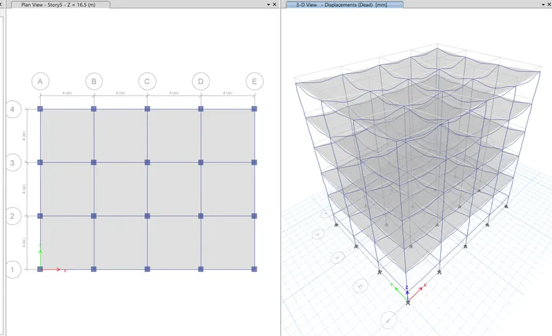
And save it as BUILDING B
Building B is done.
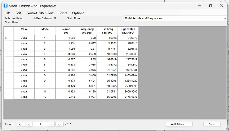
MODAL RESPONSE FOR BUILDING B:
FOR BUILDING C:
It is the same as building C, We just have to change the dimensions of the columns from 400x400 to 550x300.
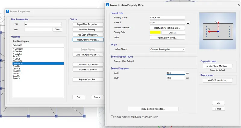
Refresh the view to check the status
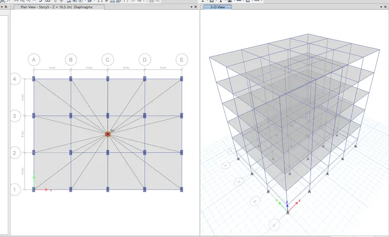
We need a Benchmark building with rectangular column orientation along the X direction.
Select all columns and go to Assign< frames< local axes< 90 degrees:
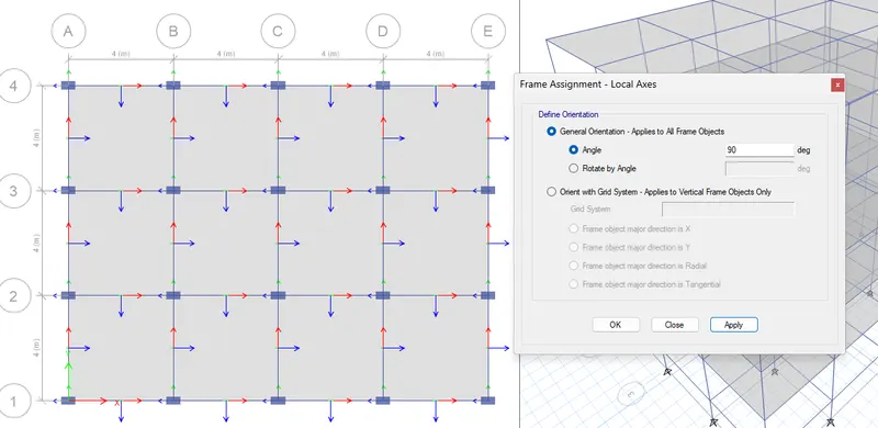
Save it as BUILDING C.
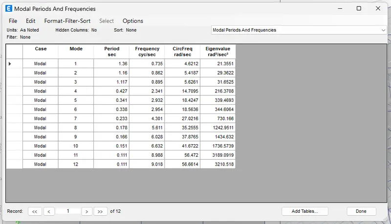
MODAL RESPONSE FOR BUILDING C:
FOR BUILDING D:
We need a Benchmark building with rectangular column orientation along the Y direction.
Select all columns and go to Assign< frames< local axes< 0 degrees:
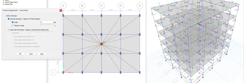
We can see the shapes of the columns are modified.
Now run the analysis.
Save it as BUILDING D.
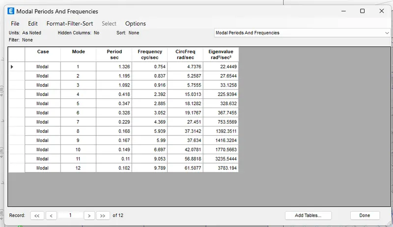
MODAL RESPONSE FOR BUILDING D:
FOR BUILDING E:
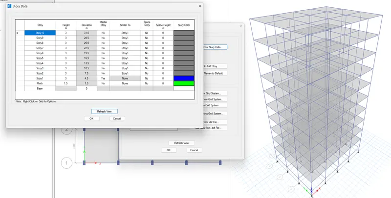
First of all, go to edit stories and grid system for Building D and add 5 more storeys to it.
Now add two new column properties to the model. that are 800X800 and 400X400:
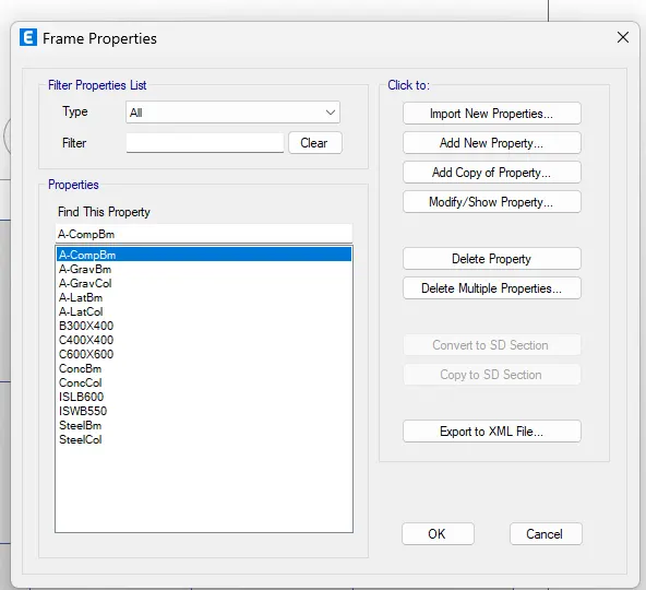
We have to assign 800X800 for the bottom 5 storeys and 400X400 for the top 5 storeys:
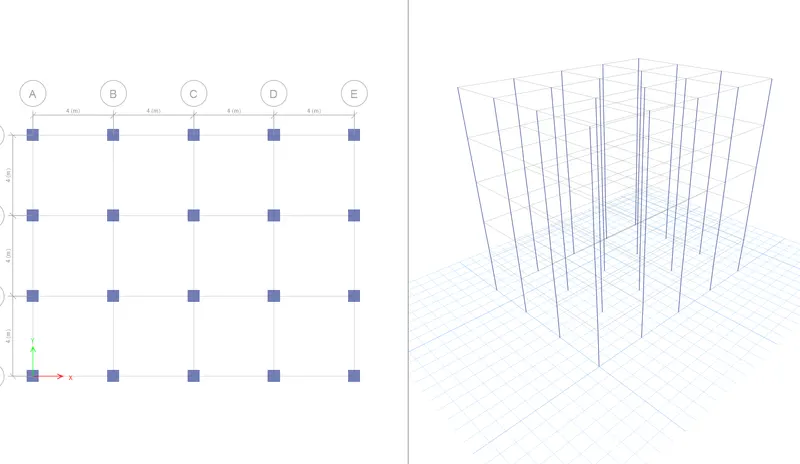
Got to set the display option and uncheck the beams and slabs:
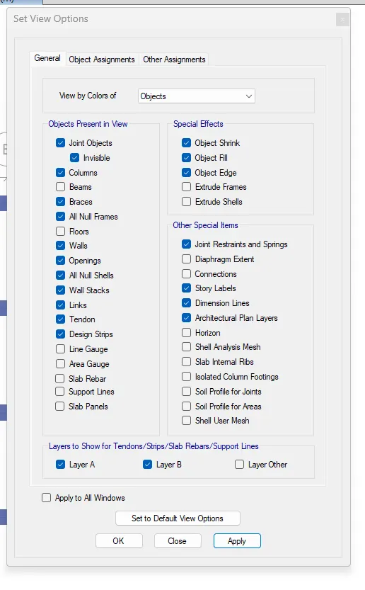
Go to view
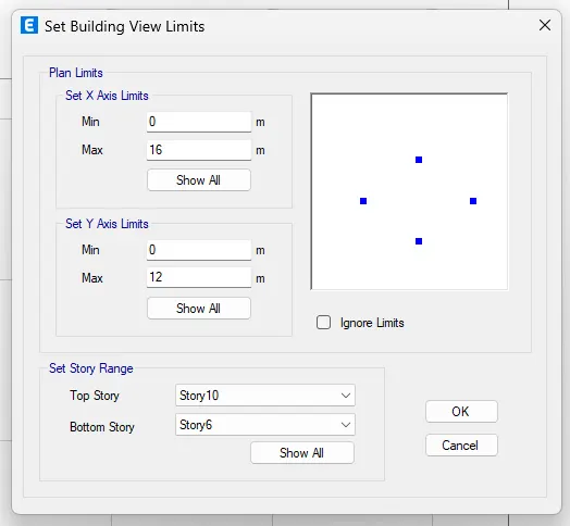
We can see that only the top 5 storeys are visible:
Now select all columns in 3D view< assign < Section properties< C400X400
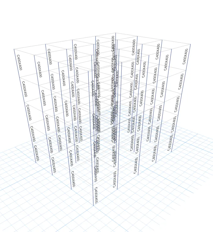
Unlock every view of the storey and we can see that the top 5 storeys are 400x400 and the bottom 5 are 600x600.
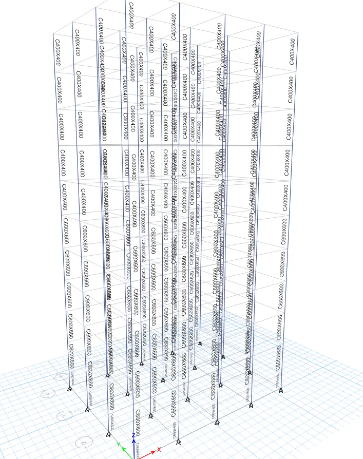
And analyze the structure:

Save it with the name BUILDING E.
MODAL RESPONSE FOR BUILDING E:
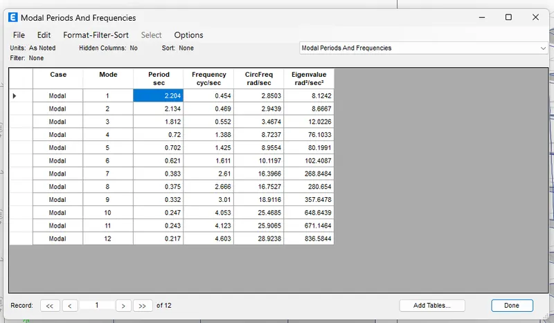
FOR BUILDING F:
Just change the column size of building E. Assign every column dimension 600X600 mm.
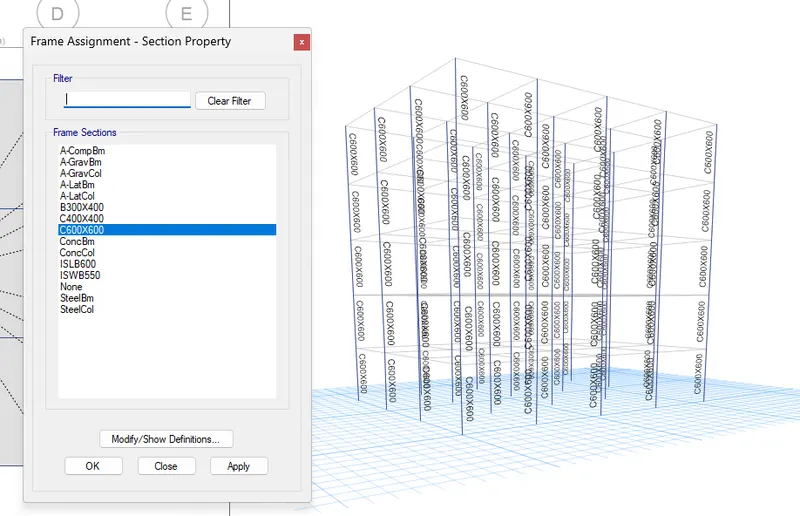
Analyze the model:
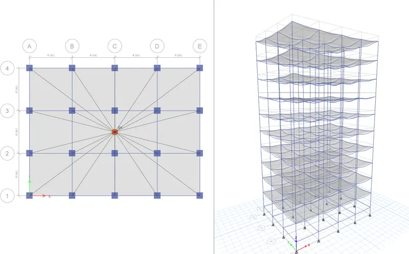
Save the model as BUILDING F.
MODAL RESPONSE FOR BUILDING F:
FOR BUILDING G:
Add 15 more storeys for Building F and make every storey similar to storey 1.
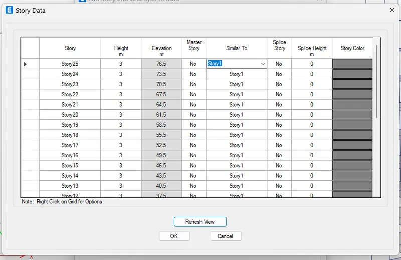
Add new section property. That is column C800X800mm
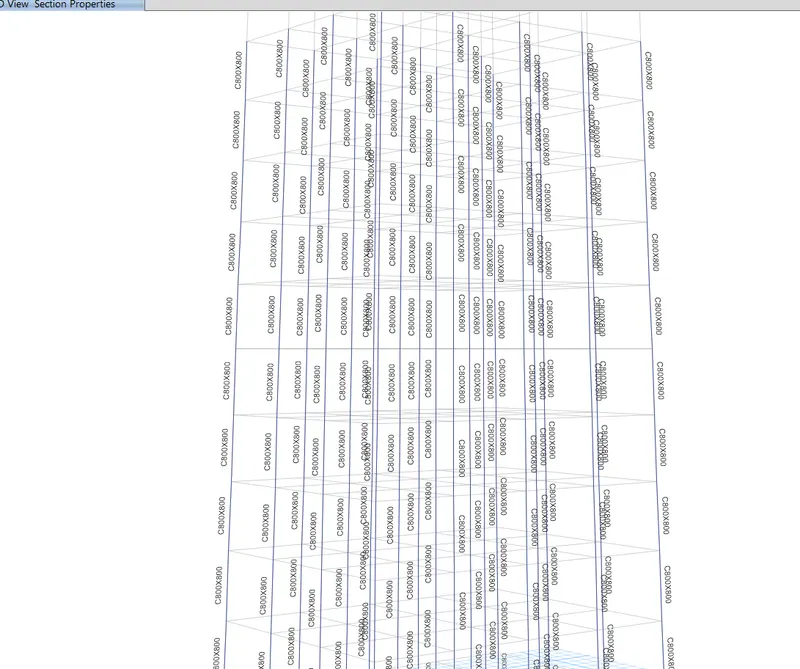
For the bottom 10 storeys assign C800X800
Use set building view limits: base to storey 10.
Use the set display option and uncheck the beams and floors.
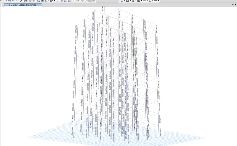
For the middle 10 storeys assign C600X600
Use set building view limits: storey 11 to storey 20.
Use the set display option and uncheck the beams and floors.
They are already 600X600
For the top 5 storeys assign C400X400
Use set building view limits: storey 21 to storey 25.
Use the set display option and uncheck the beams and floors.
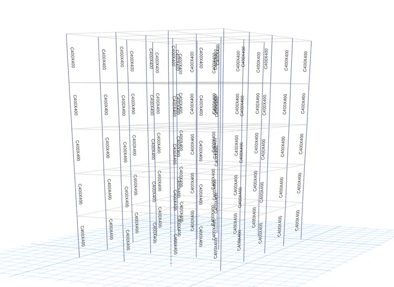
Uncheck every view and show all the storeys:
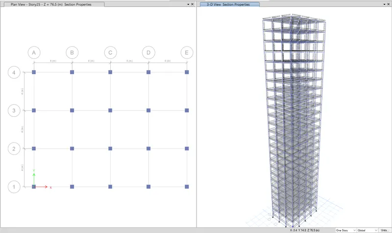
Analyze the model :
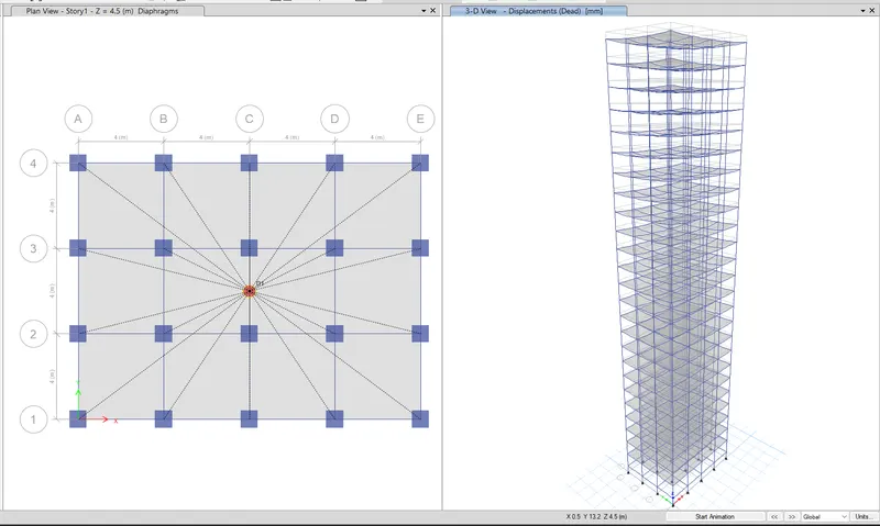
Save the building as Building G.
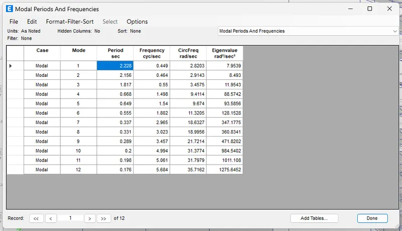
MODAL RESPONSE FOR BUILDING G:
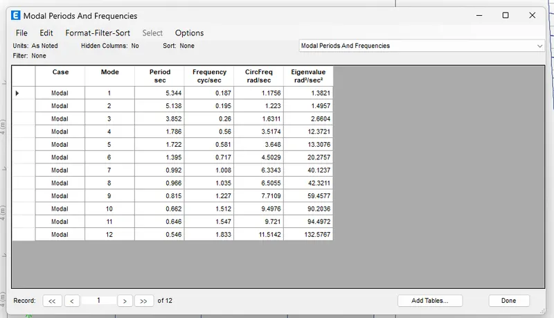
FOR BUILDING H:
Select every column in the building and assign it to C800x800
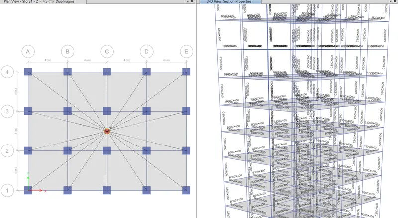
Analyze the model:
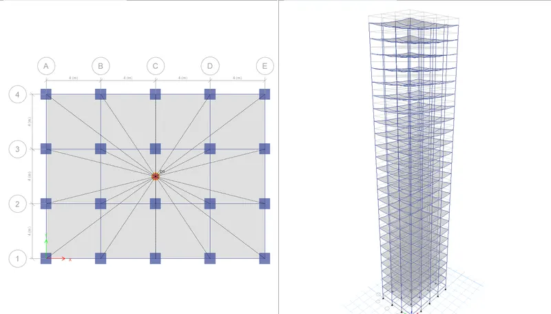
Save it as BUILDING H.
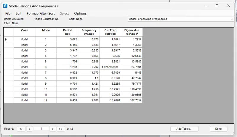
MODAL RESPONSE FOR BUILDING H:
FOR BUILDING J:
No structural changes need to be done in Building J. We need to increase the imposed loads upto 10%
Select all the slabs. Go to assign
And Assign.
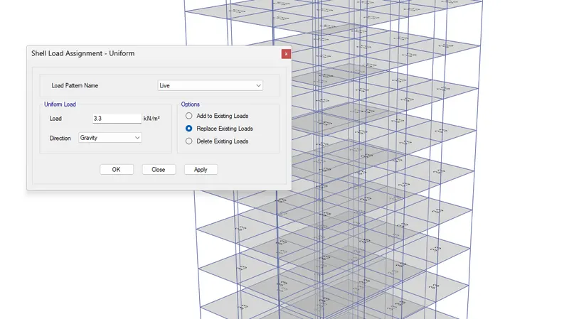
Analyze the building.
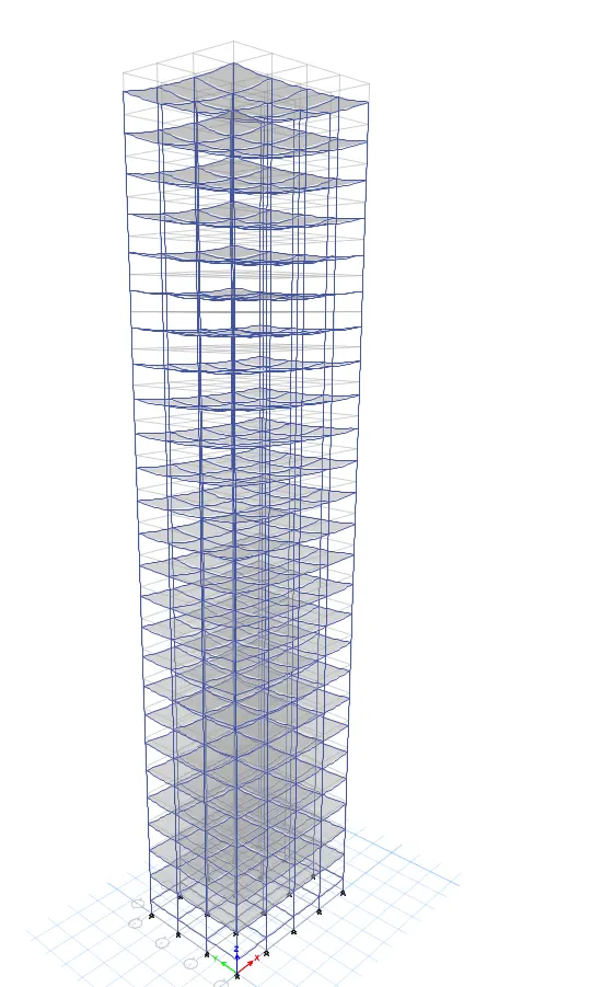
Save it as BUILDING J.
MODAL RESPONSE FOR BUILDING J:
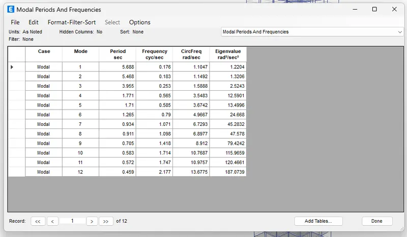
FOR BUILDING K:
No structural changes need to be done in Building K. We need to increase the imposed loads upto 10%
Select all the slabs. Go to assign
And Assign.
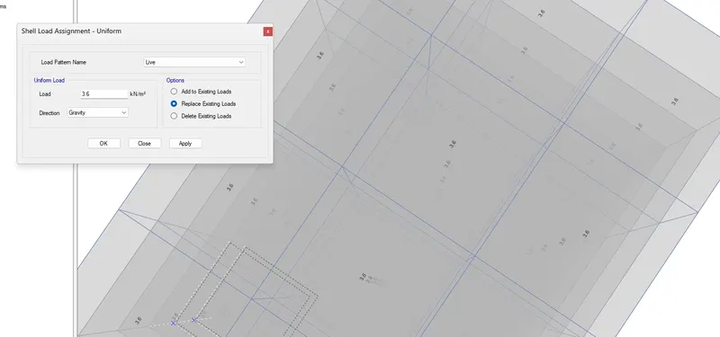
Analyze the building.
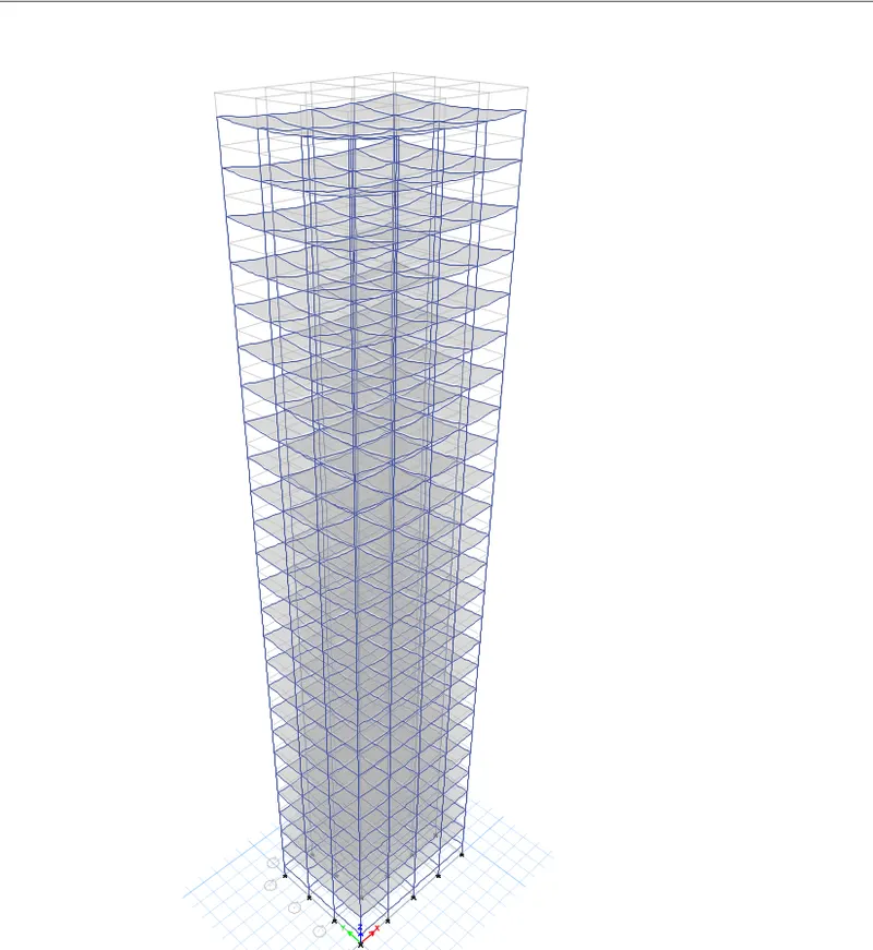
Save it as BUILDING K.
MODAL RESPONSE FOR BUILDING K:
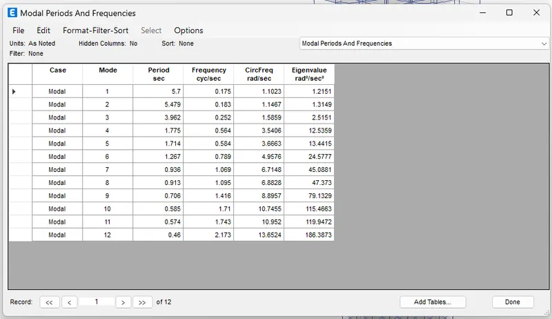
The modelling and analysis part is done.
We have to compare the effects of the time period now.
Effect of stiffness on T: Compare the fundamental natural periods of building E & F as G & H. why is the mare a marginal or significant difference in the fundamental natural periods?
Open building E F G H files.
Effect of mass on T: Compare the fundamental natural periods of buildings H, J and K. Have the buildings become more flexible or stiff due to change in mass?
Open building H J K files.
Effect of Building Height on T: How do the fundamental natural periods of buildings A, B, F and H change with a change in building height?
Open building A B F H files.
Effect of Column Orientation on T: How do the fundamental natural periods of Buildings B, C and D change with a change in column orientation?
Open building B C D files.
Analyze them.
Go to the destination displayed below to open the 'MODAL PERIODS AND FREQUENCIES' table.
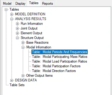
Compare the 'PERIOD SEC' of every table.
Effect of Flexural Stiffness of Structural Elements on mode shapes: Compare the fundamental mode shape of building B in two situations when the flexural stiffness of beams relative to that of adjoining columns is very small versus when it is large.
Open building B file
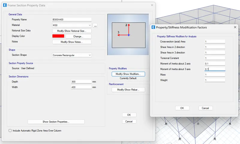
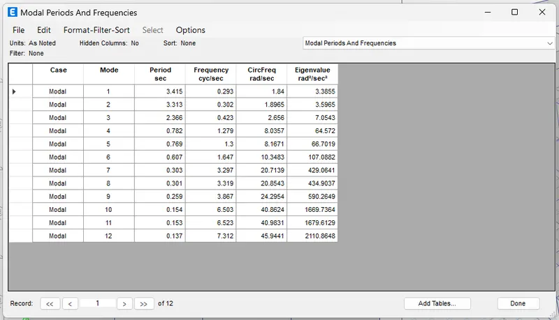
Save building B as Building B zero and modify the beam property. define<section properties<frame section< B 300 x 400< modify property modifiers and change a moment of inertia to 0.1 for 2 axes and 3 axes.
We have just removed the moment of inertia for horizontal sections.
Run analysis.
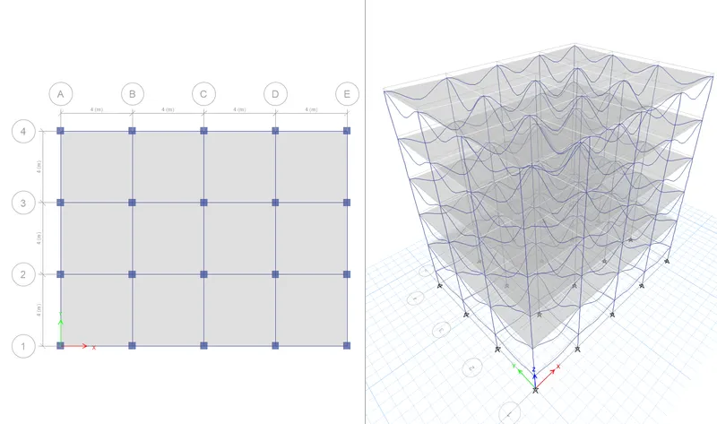
MODAL RESPONSE FOR BUILDING B ZERO:
Effect of Axial Stiffness of Vertical Members on mode shapes: Compare the fundamental mode shape of building H in two situations when the axial cross-sectional area of columns is very small versus when it is large.
Open building H file
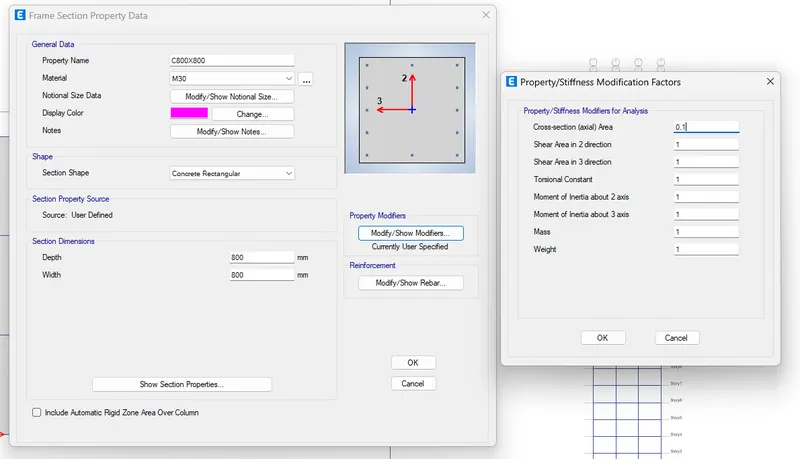
Save building H as Building H zero and modify the Column property. define<section properties<frame section< C 800 x 800< modify property modifiers and change a Cross section axial area to 0.1.
We have just removed the moment of inertia for Vertical sections.
Run analysis.
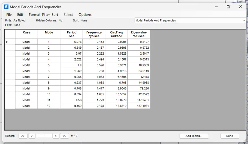
MODAL RESPONSE FOR BUILDING H ZERO:
Effect of Degree of Fixity at column bases on mode shapes: Compare the fundamental mode shape of building B in two situations when the base of columns is pinned versus when it is fixed.
Open building B file
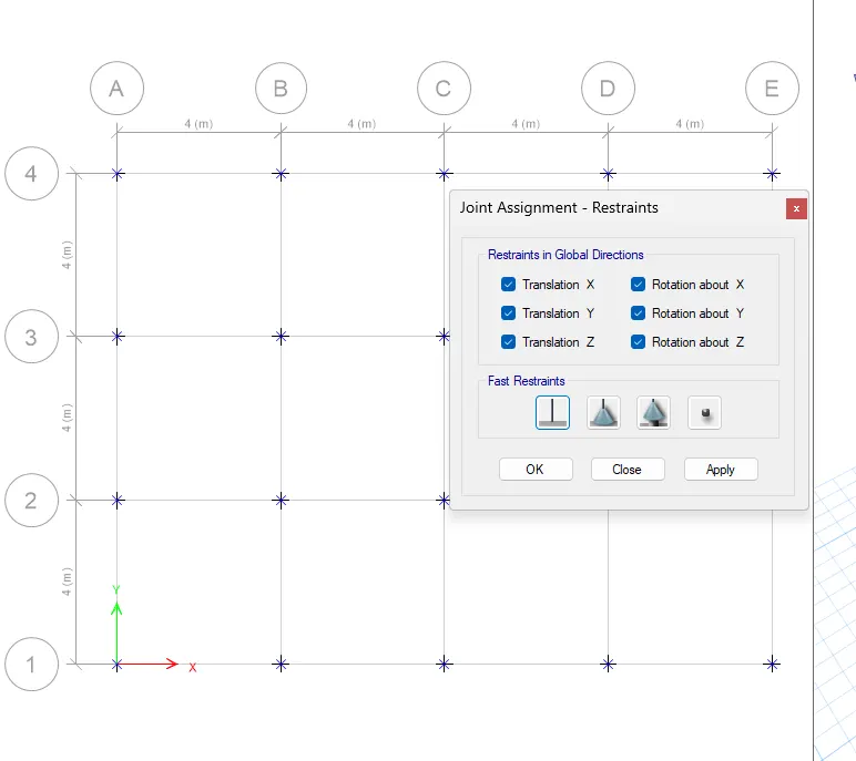
Save building B as Building B fixed to change the support condition:
Go to base plan view< select all the 20 joints< go to assign< joints< restrains< change pinned to fixed and apply
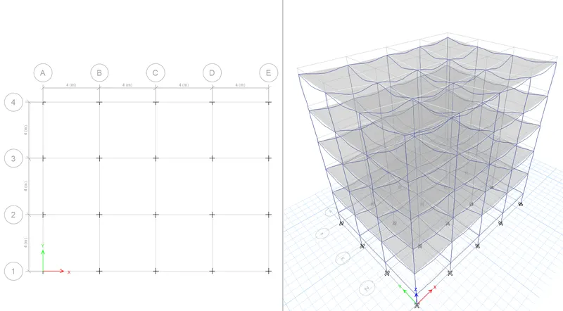
Analyze the building:
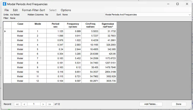
MODAL RESPONSE FOR BUILDING B FIXED:
RESULT:
| CRITERIA | MODEL | ANALYSIS RESULT | CONCLUSION |
| Effect of Stiffness on Time period | Building-E (10 Storey with varying column sizes) | 2.20 s | If the storeys are minimum then the uniform column sizes or varying column sizes have no significant difference in their fundamental time period for mode 1. Whereas if the storeys are high (in this case 25 storeys) the varying column sizes are more stable than the uniform column sizes because with a uniform column size the excess mass is lumped at the top storeys. Since the mass is directly proportional to the lateral load acting on the building that induces more lateral displacement of the building leading to a greater time period. |
| Building-F (10 Storey with uniform column size) | 2.23 s | ||
| Effect of Stiffness on Time period | Building-G (25 Storey with varying column sizes) | 5.34 s | |
| Building-H (25 Storey with uniform column size) | 5.68 s |
| CRITERIA | MODEL | ANALYSIS RESULT | CONCLUSION |
| Effect of mass on time period | Building-H (25 Storey with 3 kN/sq.m imposed load) | 5.68 s | There are no significant variations in a time period but even though the mass is uniformly provided for the whole storeys. If the imposed loads (3 kN/sq.m, 3.3 kN/sq.m, 3.6 kN/sq.m) are only provided at the top storeys and keep the bottom storey with only 3 kN/sq.m then we can see the significant variation in the time period for sure. We have to understand that mass is directly proportional to lateral displacement. So if the mass is increased it will definitely increase the displacement and time period of the building. |
| Building-J (25 Storey with 3.3 kN/sq.m imposed load) | 5.69 s | ||
| Building-K (25 Storey with 3.6 kN/sq.m imposed load) | 5.7 s |
| CRITERIA | MODEL | ANALYSIS RESULT | CONCLUSION |
| Effect of Building height on Time period | Building A (2 Storey) | 0.61 s | So as height increases then definitely the time period increases as we know the height of the building is directly proportional to the time period as per IS 1893. |
| Building B (5 Storey) | 1.27 s | ||
| Building F (10 Storey) | 2.23 s | ||
| Building H (25 Storey) | 5.68 s |
| CRITERIA | MODEL | ANALYSIS RESULT | CONCLUSION |
| Effect of column orientation on time period | Building B (All floors Column size 400X400) | 1.27 s | In the case of building B, we have the same column size in both directions and logically the response of the building in each direction should be the same, but it will not because the number of bays we are having in X and Y are different. Whereas in building C we have a higher column size in the X direction compared to building D. So, definitely the time period will be greater for Building C compared to building D. There deflection of the floor will be higher in building D than building C in the X direction in lateral load case. |
| Building C (All floors Column size 550X300) oriented in X-direction | 1.36 s | ||
| Building D (All floors Column size 300X550) oriented in Y-direction | 1.33 s |
| CRITERIA | MODEL | CASE | ANALYSIS RESULT | CONCLUSION |
| Effect of Flexural Stiffness of Structural Elements on mode shapes | Building B | Flexural Stiffness of Beams close to nil (Zero inertia) | 3.42 s | If we don’t consider the stiffness property of the beam which plays a vital lateral resisting element for the force. Which leads to double the actual time period. So this is the effect of the flexural stiffness of the beam. |
| Full Flexural Stiffness of Beams (Regular) | 1.27 s |
| CRITERIA | MODEL | CASE | ANALYSIS RESULT | CONCLUSION |
| Effect of Axial Stiffness of Vertical members on mode shapes. | Building H | Axial Stiffness of Columns close to nil (Zero axial area) | 6.98 s | The axial stiffness of the vertical member plays a vital role in the time period and a significant role in gravity design. |
| Full Axial Stiffness for Columns (Regular) | 5.68 s |
| CRITERIA | MODEL | CASE | ANALYSIS RESULT | CONCLUSION |
| Effect of degree of fixity based on mode shapes | Building B | Column support pinned(Regular) | 1.27 s | Therefore, the more the fixity of the column- the less the time period ( lesser deflection). |
| Column support fixed | 1.13 S |