Creating a Residence Layout, Seating plan, Toilet and Utility room plan using AutoCad
Creating a Residence Layout, Seating plan, Toilet and Utility room plan using AutoCad
1
AIM: To sketch the layout of a residence as shown in the figure.
INTRODUCTION: In this, sketch a new tool is introduced, known as layers. Using layers we can define the properties of different elements with different colours, line weights, line types, plotting settings, lock, freeze viewing and names.
And the tools and commands which are used for this sketch are:
- Layer and its respective options
- Xline hor/ver
- Trim
- Dimension
- Hatch
- Curves
- Rectangle
- Offset
- Line
- Polyline
- Units
- limits
- Zoom
- Arc
- Snap tools
- Orthosnap
PROCEDURE:
- Start with Taking units in engineering to plot in feet and inches with and decimal limit of 0.00.
- Next mention the boundaries of the drawing screen we have to use and start sketching.
- First, we have to define the required layers by creating the new layers in layer properties as follows:
- Status Name On Freeze Lock Plot Color Linetype LineweightTransparency
kUsed 0 True False False True white Continuous ByLineWeightDefault kUsed CB True False False True 40 Continuous ByLineWeightDefault kUsed Defpoints True False False False white Continuous ByLineWeightDefault current dimensions True False False True 16 Continuous ByLineWeightDefault kUsed Doors True False False True 160 Continuous ByLineWeightDefault kUsed hatch True False False True 43 Continuous ByLineWeightDefault kUsed stairs True False False True magenta Continuous ByLineWeightDefault kUsed texts True False False True 24 Continuous ByLineWeightDefault kUsed Walls True False False True 10 Continuous ByLineWeightDefault kUsed window True False False True 80 Continuous ByLineWeightDefault
- Status Name On Freeze Lock Plot Color Linetype LineweightTransparency
- Start drawing Walls in the walls layer using X lines, line and trim commands as required.
- The sketch is with the dimensions as shown in the figure.
- Outer wall thickness is 9.0" and the inner wall thickness is 4.5".
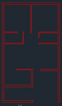
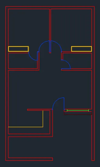
- Next, create the following units with their respective layers in the given dimensions:
- Cupboards with C/B
- Doors with doors
- Windows with windows
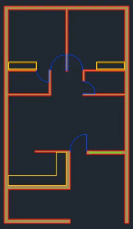
- Then go to hatch command and fill the solid hatch in between walls to make the wall look thick
- And stairs with stairs:
- Use the offset control to sketch the stairs Perfectly in 1" thread each.
- And then using the Dimension command with a desired and required dimension style, plot the dimensions under dimension layers.
- Similarly mention the Texts, and room names using the TEXT command under the text layer in the required style and font size.
- ESC
RESULT:
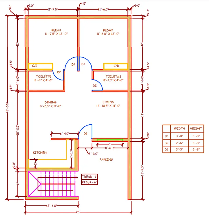
2
AIM: To sketch a seating plan for an outdoor canopy using Autocad:
INTRODUCTION: There are no new commands used in this sketch, but we use the Group option to create chairs in this.
Commands used are:
- Circle
- Centre of
- Rotate
- Dimensions
- Group
- Rectangle
- Lines
- Curve
- Fillet
- Mirror
PROCEDURE:
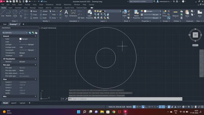
- First, draw the circles inner and outer with the radius 452 and 1398 respectively using circle and centre of command
- Next, create a unit of chairs with the following commands:
- Line
- Mirror
- Curve
- Fillet
- And make that chair as a group:
- Select the entire chair
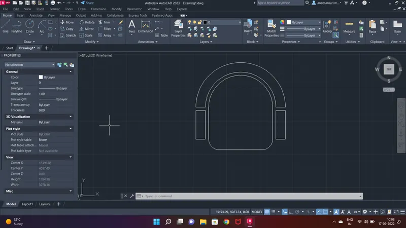
- Then move that chair to the middle area of the two circles
- Using the rotate tool and copying in it, rotate the chair at 90 degrees, 180 degrees and 270 degrees to make it look equal and perfectly placed on four sides.
- Using the dimension command, mention the dimensions of the circle.
- ESC
RESULT: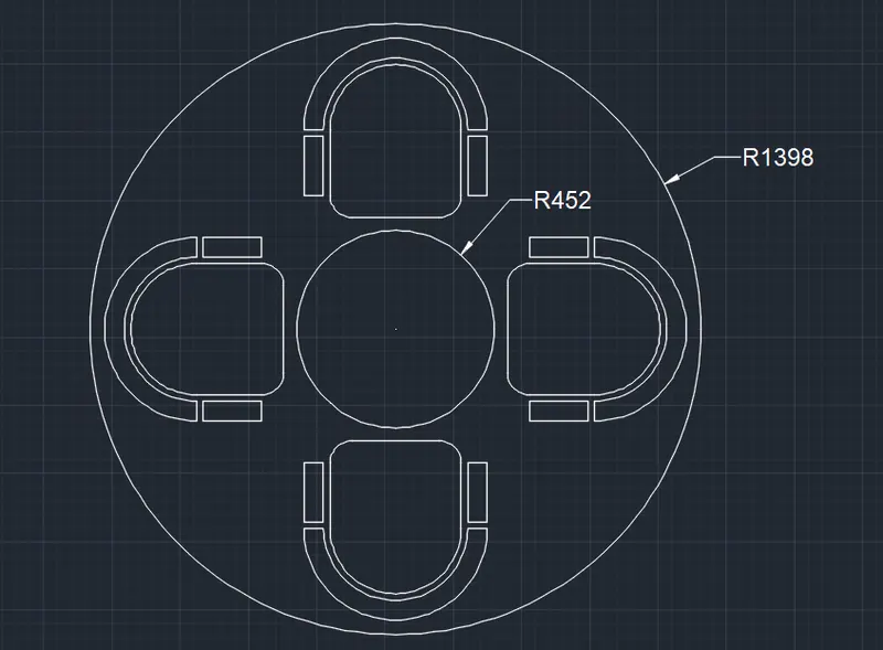
3
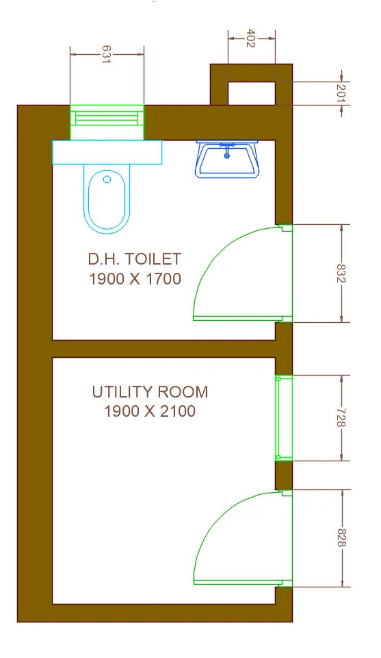
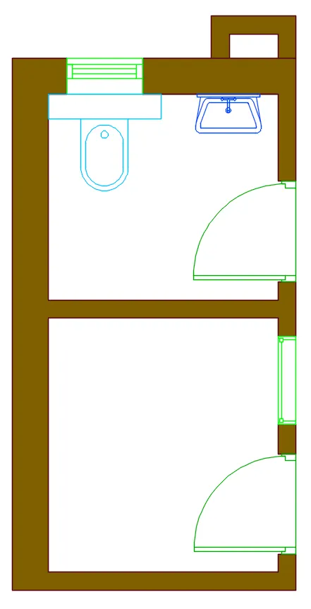
AIM: To Sketch the part plan for the toilers and utility room in AutoCAD.
INTRODUCTION: The tools and commands which are used for this sketch are:
- Layer and its respective options
- Xline hor/ver
- Trim
- Dimension
- Hatch
- Curves
- Rectangle
- Offset
- Line
- Polyline
- Units
- limits
- Zoom
- Arc
- Snap tools
- Orthosnap
- Group
- Rotate
PROCEDURE:
- Convert the units to millimetres and change decimals to 0.
- Set Limits to the sketch screen.
- First, we have to define the required layers by creating the new layers in layer properties as follows:
- Name Status On Freeze Lock Plot Color Linetype LineweightTransparency
0 kUsed True False False True white Continuous ByLineWeightDefault 0 False Defpoints kUsed True False False False white Continuous ByLineWeightDefault 0 False DIMENSIONS kUsed True False False True 25 Continuous ByLineWeightDefault 0 False door kUsed True False False True 92 Continuous ByLineWeightDefault 0 False hatch kUsed True False False True 44 Continuous ByLineWeightDefault 0 False TEXTS kUsed True False False True 252 Continuous ByLineWeightDefault 0 False toilet kCurrent True False False True 140 Continuous ByLineWeightDefault 0 False wall kUsed True False False True 246 Continuous ByLineWeightDefault 0 False washbasin kUsed True False False True 160 Continuous ByLineWeightDefault 0 False window kUsed True False False True 90 Continuous ByLineWeightDefault 0 False
- Start drawing Walls in the walls layer using X lines, line and trim commands as required.
- The sketch is with the dimensions as shown in the figure.
- The outer wall thickness is 300mm and the inner wall thickness is 150mm.
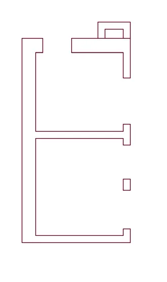
- Then go to hatch command and fill the solid hatch in between walls to make the wall look thick
- Next create the doors and windows as per mentioned dimensions:
- Toilet window: 631mm - window layer
- Toilet door: 832mm - door layer
- Utility RM window: 728mm - window layer
- Utility RM door: 823mm - door layer
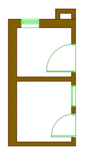
- After that create the toilet in toilet layer seat using :
- Rectangle
- Curve
- Lines
- Circle
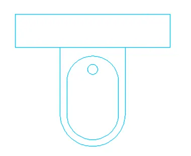
- And make it as a group.
- And then create the wash basin in the washbasin layer using :
- Lines
- Circles
- fillets
- Curves
- Mirror
- Copy
- Rotate
- Snap tools
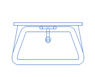
- And make it as a group.
- Place both of them in the desired place.
- And then using the Dimension command with a desired and required dimension style, plot the dimensions under dimension layers.
- Similarly mention the Texts, and room names using the TEXT command under the text layer in the required style and font size.
- ESC
RESULT: