Assignment 7-Side Pole Crash Simulation Challenge
AIM
Run the side pole crash simulation of the given car body with below mentioned boundry condition and interface parameters.
Neon side crash -BIW
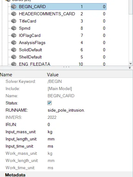
- Check unit system and either follow [Mg mm s] or [Kg mm ms].
- Create an appropriate interface, friction 0.2, and recommended parameters.
- Make sure of no penetration and intersections.
- Create a rigid wall with friction 0.1 as per the reference model.
- Compare the model weight with the reference model and use added masses to reach the target weight of 700kg while getting CG about the required range.
- Initial velocity - 35mph, as per the standards.
- Use model checker to ensure good quality.
- Timestep :0.5 to 0.1 microseconds.
- Run 80ms.
Output requests:
- Sectional force in the cross member.
- Intrusion at B pillar,hinge pillar and fuel tank region. Provide recommendations on what can help to reduce Fuel tank intrusion.
- Peak velocity of an inner node of the door.
MODEL
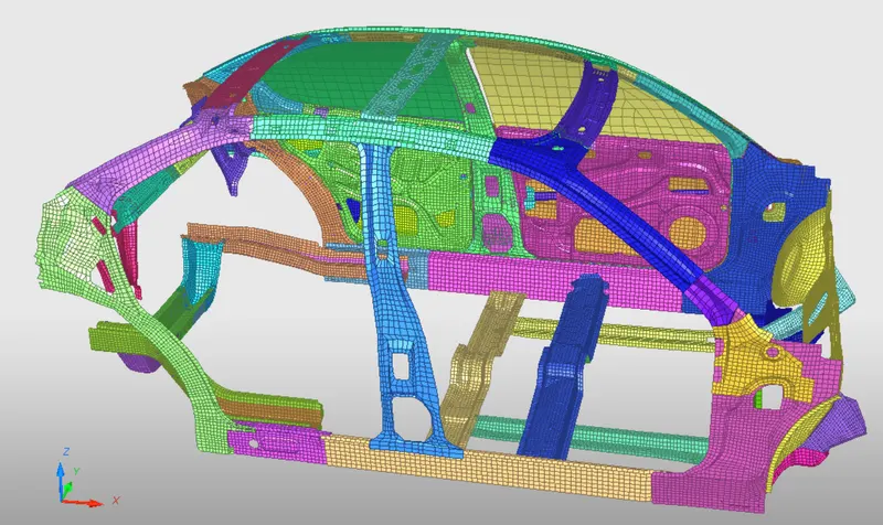
Introduction
Protecting people in side crashes is challenging because the sides of vehicles have relatively little space to absorb energy and shield occupants, unlike the fronts and rears, which have substantial crush zones. Automakers have made big strides in side protection by installing side airbags and strengthening the structures of vehicles. The Institute's testing program has played a key role in bringing about these improvements.IIHS began its original side test program in 2003. At that point, the federal government was already performing side tests on new passenger vehicles as part of the New Car Assessment Program. But we were concerned that the government's test didn't completely capture the types of crashes likely to occur in the real world.Engineers look at three factors to determine side ratings: driver and passenger injury measures, head protection and structural performance.
PROCEDURE
- Open the hyperworks software
- Import the solver deck file in the hypermesh in radios format.
- Here we are importing starter file
Check unit system and either follow[Mg mm s] or [Kg mm ms]
- To check which unit system follow the procedure Model > Cards > BEGIN_CARD.
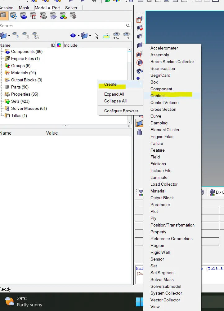
Create appropriate interface ,friction 0.2 and recommended parameters
- Next step is to create Interface contact for the car model. Inerfaces are defined to model how parts interact when they come into contact with each other.(Right click>create>Interface)
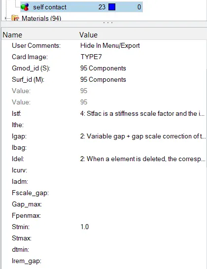
- Here we are using type 7 (node to surface) interface and add appropriate parameters.
- Select all the components in surface ID.
penetrations and intersection
- To check the penetration export the model from hypermesh and import the model in Hypercrash.
- Penetration check is used to check wheather any components are intersected or penetrated with each other.
- To check penetration go to Quality>Check intersection of tree selection>include picked parts >select the components by box selection>Right click.
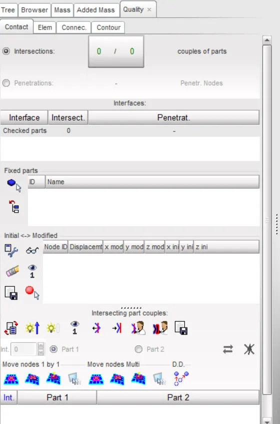
- There is no penetration or intersection in this components.
Create rigid wall with friction 0.1
- Rigid walls allow for an easy way to define a interface between a rigid surface and nodes of deformable body.
- To create go to Solver Deck > Right click > Rwall > cylinder.
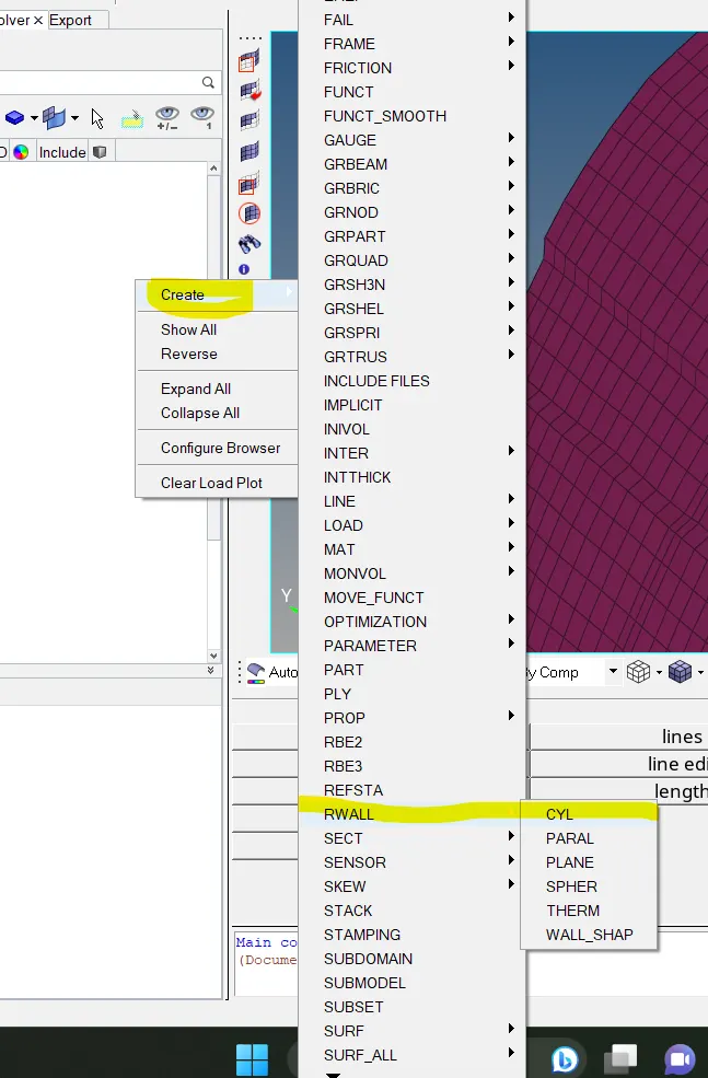
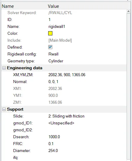
- Give sliding friction 0.1 and select any node on the side door panel and change the coordinate into z as an axis normal.
- There should be some gap between node that selected for rigid wall and side door.
- Give search distance as 1000mm and diameter as 254 mm.
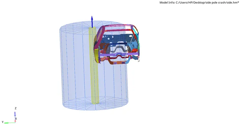
- The model with rigid wall is shown below.
Mass Balancing and COG
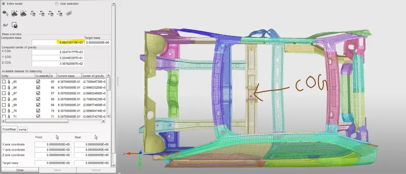
- Import the file in hypercrash and go through Mass>Balancing.
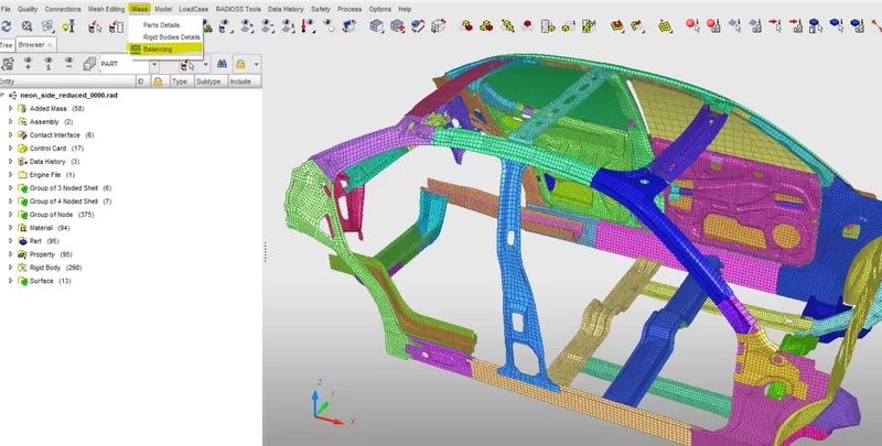
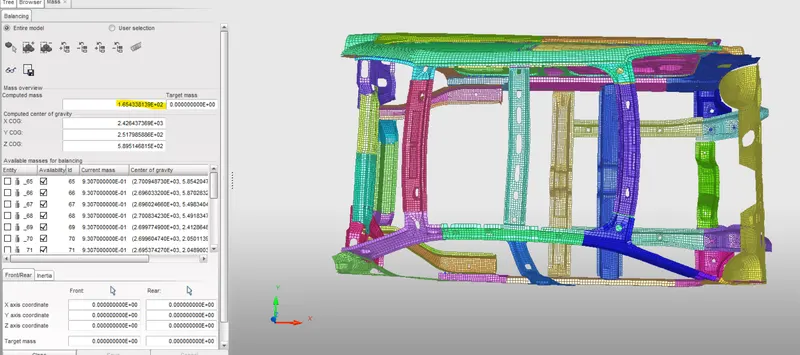
- Now we can see total mass and some added mass in the list.
- Identify the COG in the car body
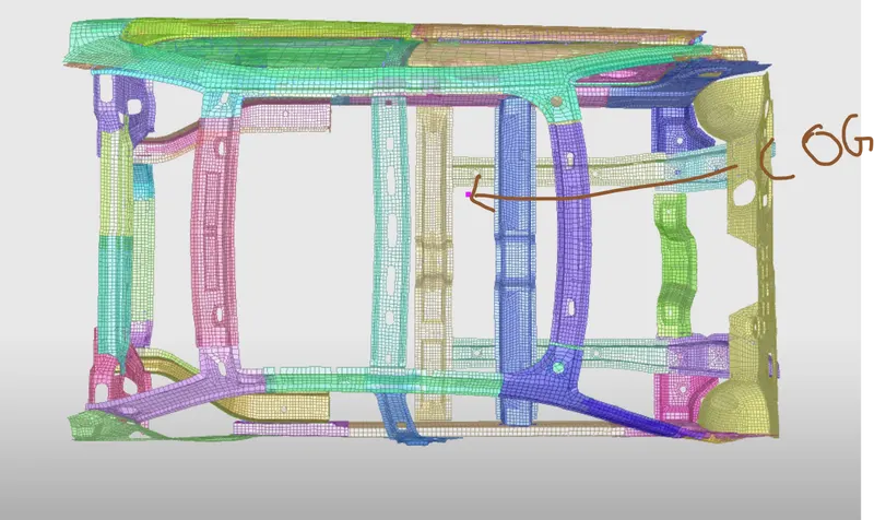
- From the above dialog box we can find that total mass of the frontel body is 188 kg. We have to add mass upto 700kg because here the given mass is only consider the weight of BIW components only.We need to include the weight of trims and passengers also so we add additonal mass to the body and change the positon of COG to the center piller of car body.
- Create add mass and add mass by selecting the required nodes. Generally we are assigning the mass in whole of group of nodes.
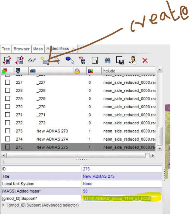
- Here we are creating two add mass and assigning mass until COG comes into proper position.
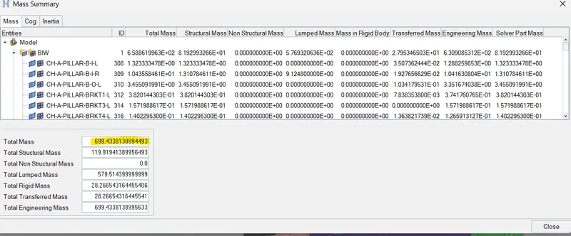
- After adding mass we need to export the file andimport it in hypermesh.(File>Export>Radioss)
- Check the mass details in hypermesh.
Initial velocity
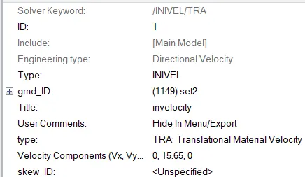
- The velocity input for this simulation as per the Standards is 35mph so when we convert it to m/s the input velocity is 15.6464m/s.
- To create a velocity Go to solver browser >> Create >> boundary conditions (BC) >> Inivel
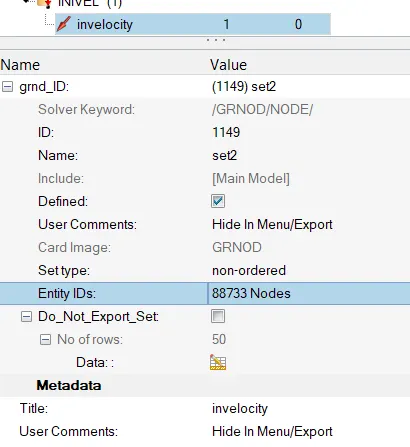
- Define the Node group on which specified initial velocities are applied (grnd_ID1). For our simulation, we will be selecting the whole vehicle setup.
- The velocity type is selected as Translation velocity and it is provided in the y-direction as shown in the below image.
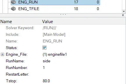
- Change the engine run time into 80ms.
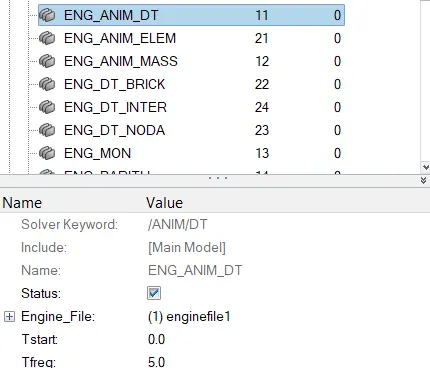
- Go to ENG_ANIM_DT card enter T freq as
Creating Sections
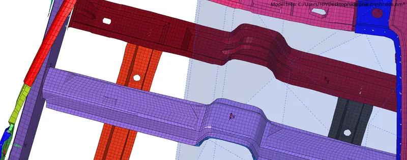
- We are going to create Sections at cross members in order to Study the sectional forces
- We have to know how the forces are transmitted through the vehicle body.
- We are using moving frames to create a section as shown below.(Go to solver deck>Right click>create>Frame>Mov)
- create mov frames for both cross section.
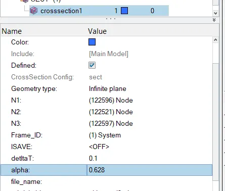
- To Define sect Go to solver deck>Right click>create>Sect
- Define the Nodes with reference to the Axis of the Frame.
- Enter the values of Delta T as 0.1
- Define the cutting plane by a group of elements and its orientation by a group of nodes (grshell_ID)
- Hence, the sections will be created.
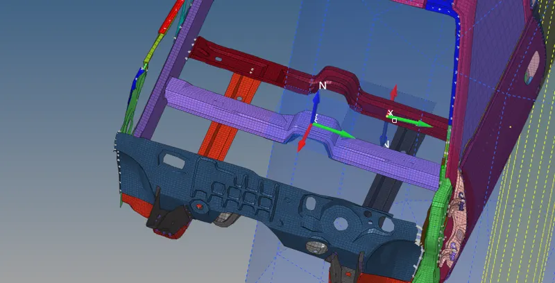
- The next step is to create TH card for requesting the outputresult.(solver deck>right click>Create>TH>Sect)
- Define the entity id and variables in TH card.
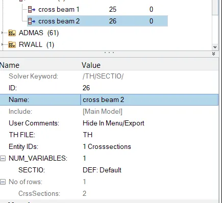
- Do the same procedure for creatind section in both crosssections.
Intrusion at B pillar,hinge pillar and fuel tank region
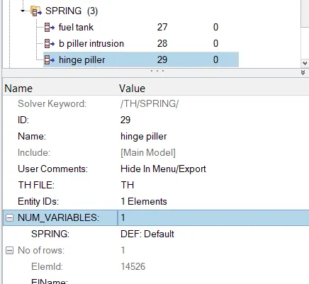
- We are planting spring elements to study the intrusions(forces inside the B-piller,hingepiller and fuel tank causing deformation/rupture)
- Create 3 parallel spring elements from the the Crossbeam to fuel tank,B piller and Hinge piller.(1D Panel > Springs )
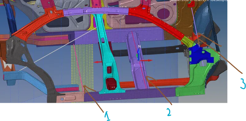
- We have to provide the springs with their respective properties.Go to model Browser > Create >Property >Rename as Springs
- After creating a property, a new tab will open there we have to select CARD image as P4 SPRING and Mass as 0.001, and Stiffness as 0.001 and assign all these properties to the spring.
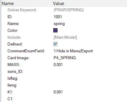
- Make sure to create a Time History file for these Springs Individually so that we can view the intrusions.(solver deck>right click>Create>TH>Spring)
Peak velocity of an inner node of the door
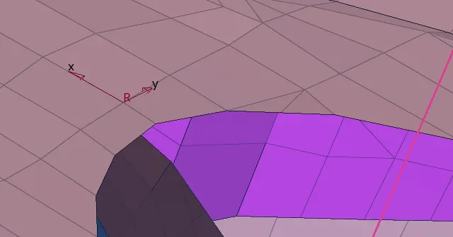
- To find peak velocity at the inner node of the door, we will create a moving frame at the node location by using right-click on solver browser > create > skew > MOV
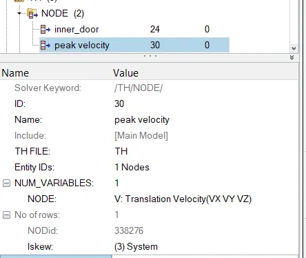
- The next step is to create a Time History (TH) output specifically for this. For that, we can switch to the model browser and create a new output block, this time for peak velocity(right-click>create> output blocks). for lskew, we shall be selecting the skew created previously.
Model Check
- The Model checker will give us any warnings and Errors regarding the model definition , the boundary and Kinematic conditions.(Tools>Model checker>Radioss)
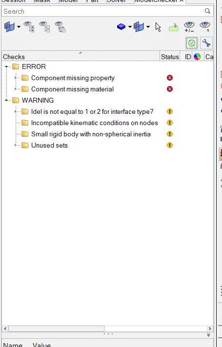
- We can clear it by using autoclean up.
- After applying all the boundry condition and Kinamatic condition , we have to run the analysis (Analysis > Radioss > Input File (File Location) >Radioss)
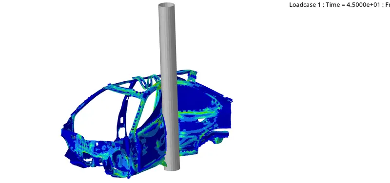
RESULT
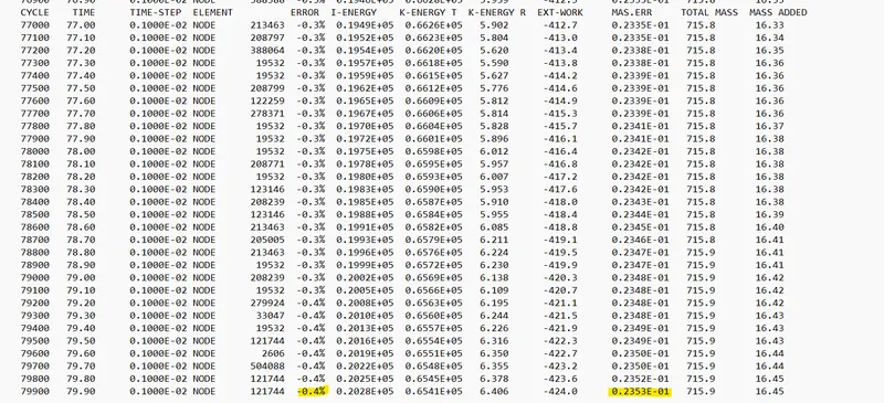
- As we can see, the energy error is -.4%. It is definitely acceptable due to its proximity to 0% error. In addition to that, the mass error is in also acceptable range.
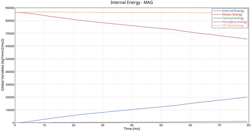
- The changes in kinetic and internal energies occur at the exact moment the BIW makes contact with the rigid cylindrical wall. Understandably, the BIW loses kinetic energy throughout the simulation due to the obvious decrease in velocity. At the same time, it absorbs the forces, and this results in an increase in internal energies, and as a result, the deformations also occur.
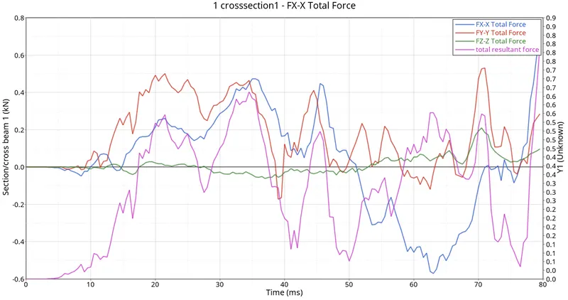
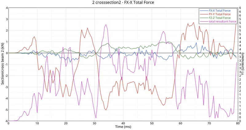
- Cross-members are very crucial in the side-impact analysis as these components prevent the body to shrink or deform inward. When the car hits the rigid body maximum amount of forces will pass through the cross member of the base and roof. This component along with door bar and support, door outer, B pillar, and rocker are also involved in the majority to prevent deforming. But the forces acting on every other component eventually pass from the cross member.
- The max sectional force at the B-pillar cross member is 0.803 KN at 79 ms and for the driver seat cross member it is 5.11 KN at 34 ms.
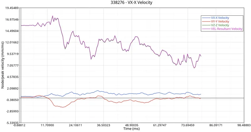
- As we all know that when the car hits the pole first impact will be the door and due to the deformation, the inner portion of the door might hit the passengers inside the car and lead to injuries. Hence it is important that the Peak velocity at the door region is to be calculated.
- From the Graph, the peak velocity of the node on the door is 17.73 mm/ms at 14 ms.
- Velocity is decreasing through out when time is increasing.probably due to the folding deformation created as the crash progressed (due to inertia). As time passes, we can see the velocity gradually decreasing.
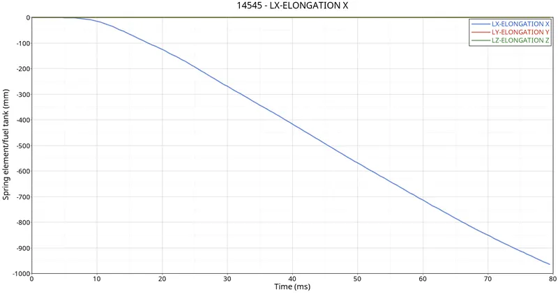
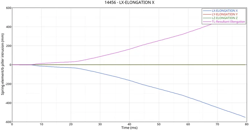
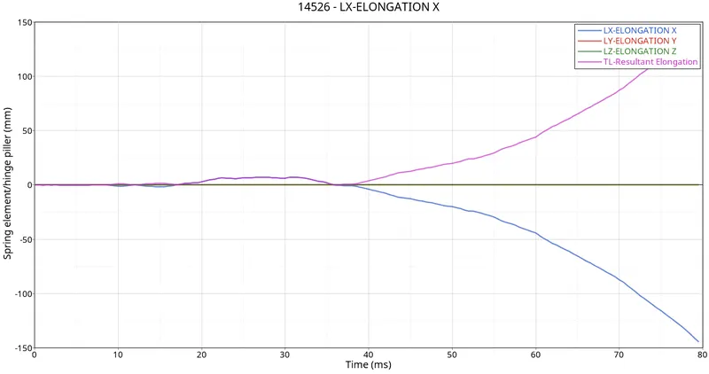
- The intrusion or deformation of the component can harm the occupants and the inner part of the car like a fuel tank. From the above plot, it is obvious that intrusion near the fuel tank is 947mm and near the B pillar is 546 mm which are substantial and Hing piller have 144mm elongation.
- The fuel tank region received the highest displacement, followed closely by the B-Pillar, then the Hinge Pillar. Admirably, the B-Pillar was able to absorb a lot of the impact due to multiple reinforcement members attached to it and in its vicinity, despite being one of the first regions of impact in the crash. The hinge pillar did not have any reinforcements and hence suffered the most displacement.
- The alternative method used for reducing the intrusion near the fuel tank region is the additional crossbeam. The crossbeam is situated between the base and C pillar .
CONCLUSION
Side crash analysis was carried out on the given BIW model of the Dodge Neon as per requirements. The output requests were also generated after the creation of cross-sections in each of those regions. Peak velocity and intrusion values were also measured at certain points of the model.