Week 6 - Creating connection for Rear door
AIM
To perform the connection of the rear door of the car with different connections techniques and assign pid for each components.
MODEL
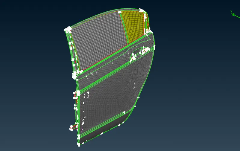
PROCEDURE
- Import the Rear Door Model in ANSA Preprocessor
- Here we are dealing with different types connections that is mainly useful in simulation of mechanism.
- There are different types of connections used in ANSA such as Door hinches,rear windows,bolt connections etc.
- Now Create different PIDs to the model for your convenient to give connections.(Topo>face>Set PID).
- In the rear door mainly used connections are spot weld connection, Bolt connection, RBE2 connection,CBUSH connection etc.
- Now we can start with RBE2 connection in hinge areas. First select elements-RBE2 in nastran deck. Select RBE2-many nodes by using loop option and enter.
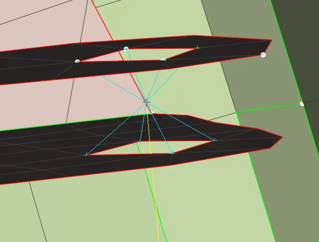
- From the above fig we get an cluster RBE2 connection.In RBE2 connection center node is known as Master node and rest is slave nodes
- These two cluster RBE2 connections are connect with two Node RBE2 connections.
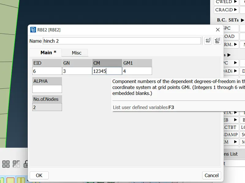
- This two node RBE2 spindle represent door hinch connection. In door hinch connection only five DOF should be constrainted.(NAST>Element>RBE2>Two)
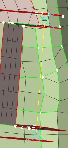
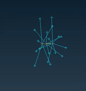
- Now repeat the process for the hinge bolt holes. Many node RBE2 involves connecting many nodes into single spider by depend of single master node
- The another way to assign bolt connection which becomes more easy to connect the parts. Here we have 2 more components to connect so we need to create the COG point in the centre component by using Topo>points>on COG.
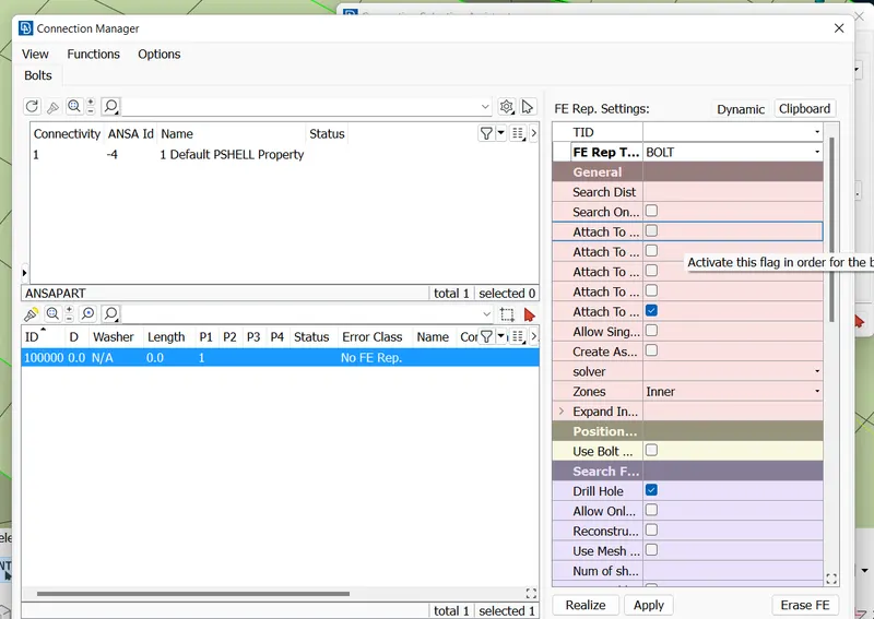
- Select the COG point and convert COG point as Bold by using convert>3D point>bolt. now select the connection manager tool to do further steps for bolt connection.
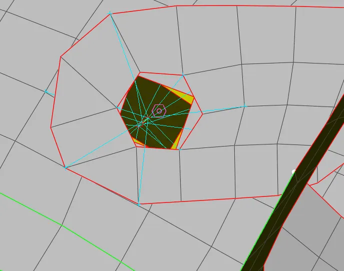
- we have to assign p1,p2,p3 (if 4th part is there, have to assign p4). to assign p1 by right click p1 tab and press f1 to select the component and click enter to finalise. now assign all p1,p2,p3 now select FE rep type as bolt. assign search distance as 40mm, zones as in/out, DOFs to be 123456. now apply and realize the bolt connection.
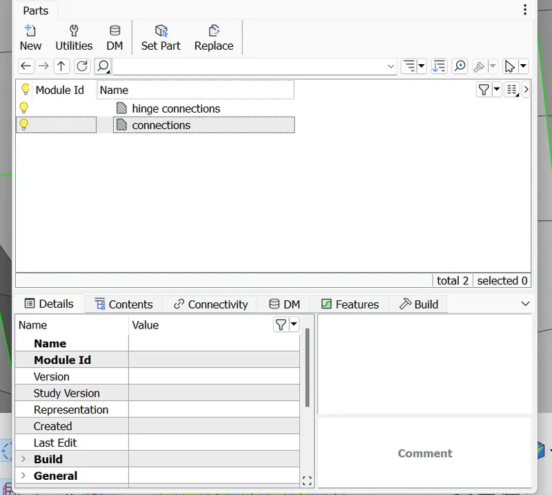
- Create supperate files to store connections in model browser.
- Next we have to create weld connections in particular PIDs. We are mainly use spot weld
- For Spot welds, We have different method. At first create COG point using on COG tool. assign COG point as 3D point and convert 3D point to Spotweld point by using Convert>3D point>spotweld.
- Now select connection manager and select spotweld point. assign P1 and P2 for selecting PIDs. Assign FE rep type as RBE3-HEXA-RBE3. Assign RBE3 pinflags as 123456. select realize the spotweld deployed at the point.
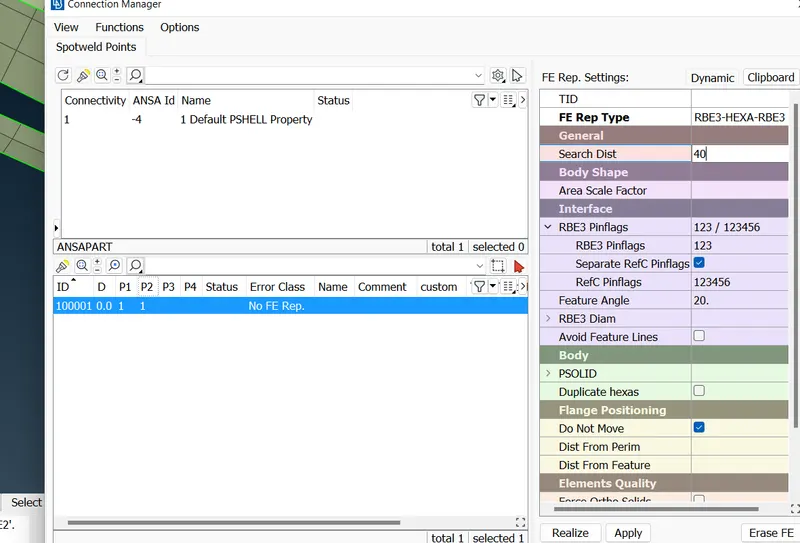
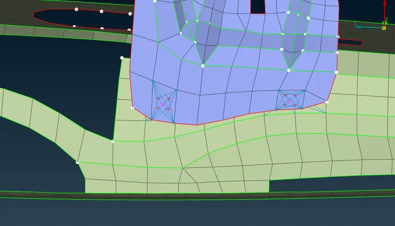
- Give spot weld to required part connections.
- Now move to door handle area, Deploy the rigid connection to the holes in door handle by using RBE2>many nodes tool. now we have two master node. now select two master nodes to connect by selecting RBE2-many nodes tool and create master node at the centre.
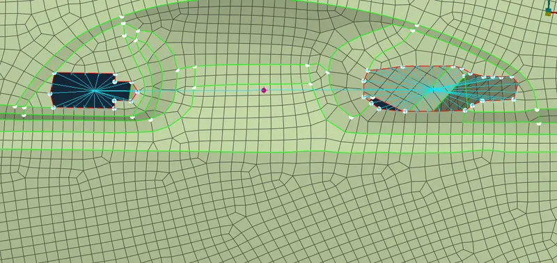
- Connect the two master nodes by using RBE2>many nodes and assign conmass using NAS>Elements>CONMi>CONM2>Nodes.After selecting the master node, here we have to give mass value (M) in window appeared. the mass value will be tonnes so convert 100g into tonnes as 0.0001. Now select ok to assign the con mass.
- Now we have to connect the window glass using CBUSH connection. For that to begin with create curves using glass edges by using tool as mesh>perimeter>feat2curve.
- Now offset the curve for distance of 10mm by using tranform-copy.
- After offset, we need to convert the curves one by one into spot line by selecting convert>curves>spot line
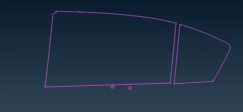
- After that select connection manager to do next step. assign p1, p2 (p3 if it needed) after this select FE rep type as RBE3-CBUSH-RBE3. assign search distance as 40mm, check the keep all branches option.
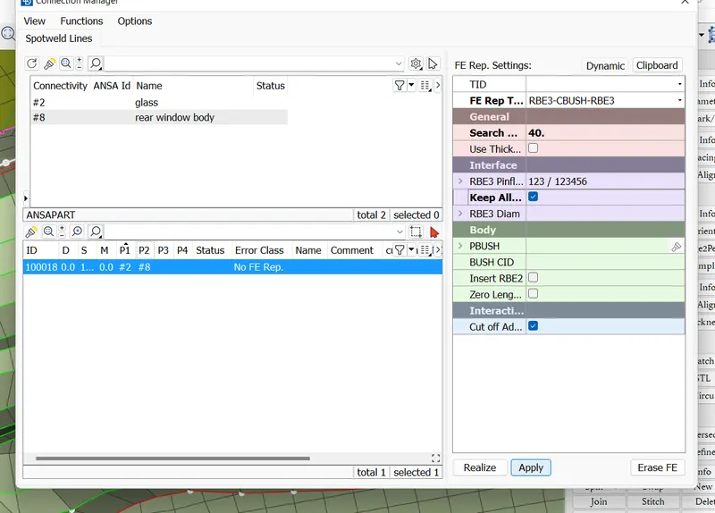
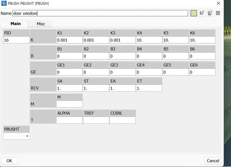
- Assign PBUSH ID by clicking the tab we need press shift+?. the PBUSH ID window appears, assign required stiffness (k) values are as follows.
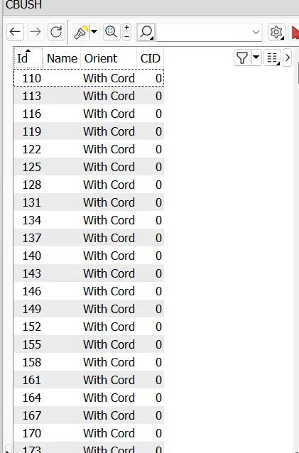
- Now we have to reorient the local coordinates to global coordinate system. By selecting Database>elements>CBUSH and select all the CBUSH, Right click and select modify. Ater the selection modify tab appears, assign orient-with cord and CID-0. select ok to all. Now the local coordinate system is changed to global one.
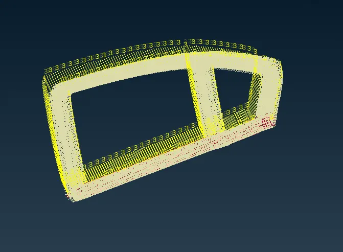
- After all this, give realize and the result shown below .
LEARNING OUTCOMES
- Learnt how to convert the points and curves into connecting lines and points using convert and connection manager tool.
- Learn how to assign RBE2, RBE3 connections ,spotweld connections and CBUSH connections.
CONCLUSION
The suitable connections were deployed as per the requirements for the given rear door FE model.