Week 12:Project-1-Meshing of Door Inner Panel Challenge
AIM
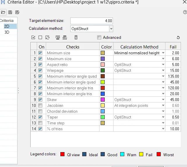
Follow the Quality Criteria and mesh the side door component and assign thickness:
Target Element Length = 4 Units
| S.N | Quality Criteria | Value |
| 1 | Aspect Ratio | 5 |
| 2 | Skewness | 45 |
| 3 | Warping | 15 |
| 4 | Taper | 0.5 |
| 5 | Min. Length | 2 Units |
| 6 | Max. Length | 6 Units |
| 7 | Min angle Quad | 45 |
| 8 | Max angle Quad | 135 |
| 9 | Min angle Tria | 20 |
| 10 | Max angle Tria | 120 |
| 10 | Tria % | 10 |
MODEL
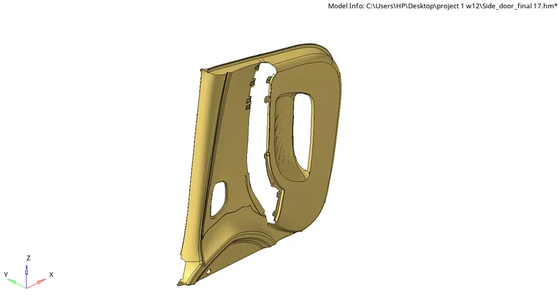
PROCEDURE
- Open the hyperworks software
- Select "import geometry" option and also set the file type format, then import the first model.(import geometry>model>open)
- we have to clean up the given model by removing the holes and unfilled surfaces (Geometry>quick edit>fill hole)
- As the model consists of the various components we should extract the midsurface for the each components and do the topology clean up(geo>autoclean up)
- There are so many features in the side door model such as ribs,resting pad etc.We have to capture all of it. So manuel midsurface is the method that we are going use here.
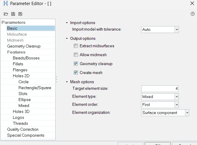
- Before that give the quality criteria and mesh parameters for the given model and save it as supperate file.(Preference>criteria file settings/parameter setting)
- Next step is to extract mid surface from given side door model. There are two methods for generating mid surface. Automid and Manuel offset method.Some area of plastic or sheet metel components we can't use auto mid method. It will not give proper result. So we use manuel method.
- First we are going to extract mid surface of side door outer surface and then go to the iner features.
- Find the thickness of the component (F4)
- Here we extract mid surface by manual offset method.(Geo>surface edit>offset)

- Select a surface of component and leftclick on surface icon and select by face option than we get all faces be selected. give offset value check vector normel and add duplicate and off set the surface
- Follow the above procedure for generating side rest also.
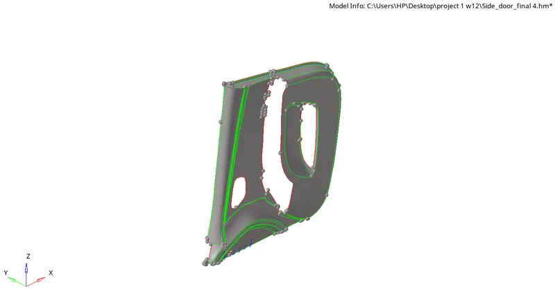
- Next step is to generate midsurface for the ribs and other small features.
- Create a mid curve on the top of the rib as shown below.(geo>surface>midline)

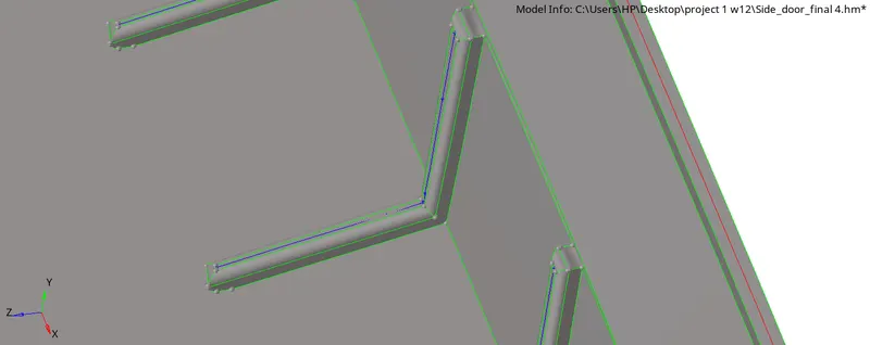
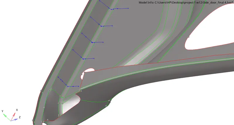
- Project the duplicates of the line to the surface.(Tools>Project>To surface>Lines>select surface)

- Create surface by using surface ruled option in surface panel.(Goe>Surface)
- Do similar For all rib sand other features.
- We can also have an alternate method for generating method fo extract mid surface by using midsurface tool.(Geo>midsurface>final edit tool)

- After creating mid for all features extend these to the main surface.(Geo>surface edit>extend)
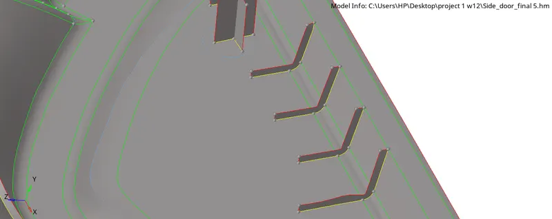
- Connect all features to the main surface by using extend tool.
- Now go the auto clean up option in the geometry menu and select mid surface to be meshed.(geo>autocleanup)
- Divide the midsurface into different parts and move each part into different collectors.This is for the simplicity of meshing process.(Tools>organize).
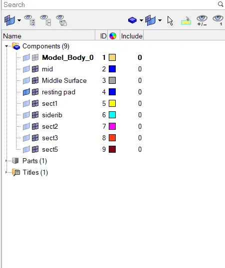
- Do meshing part by part.It will reduce our time and give good meshflow.
- Before meshing toggle the edge where minmum length be failed and unwanted divisions and divide the model into different sections.(F11-Quick edit)
- Create lines where is necessary by using the split surf node & split surf line tool.(geo>quick edit)
- After the geometry cleanup, go to 2D mesh menu and select automesh option, change the element size to 4, element type to mixed and select the mid surface and click mesh to generate the mesh.(2D>automesh>select surface>mesh)
- Mesh the area by area for the good mesh flow
- After completed the meshing awe have to check quality so shift the view into by element quality
- clear the element off elements by using element clean up tool.(2D>element clean up)
- We can use quality index tools for adjusting the elements nodes and remove off elements. (2D>quality index)
- Do the above steps for all parts and move all into a single collector.
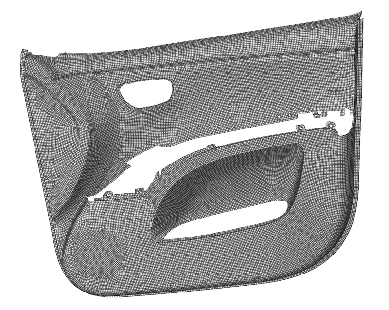
- Next step is to assign thickness for each featuras.There are many ribs and otherfeatures with different thickness.So create components for each features and move to respective collectors assign properties for each features.
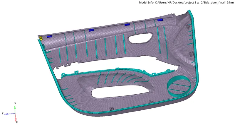
FINAL MODEL
CONCLUSION
The given side door panel was meshed as per given quality criteria. Due to it being a plastic component, different regions having different thicknesses was prevalent and the component was split into multiple sub-component and they were assigned their respective thicknesses.