Assignment 5-RADIOSS Interfaces & Study of Effect of Notches Challenge
AIM
Create the mesh for bumper assembly,mesh size should be 6mm.
- Run the crash tube model as it is.
- Change the Inacti=6 and run.
- Create the type 11 contact and run.
- Remove both notches and remove boundary condition on rigid body node then run.
- Create a new notch in the middle ,select the whole section and run.
- Create a new notch with nodes only from opposing 2 faces and run.
MODEL
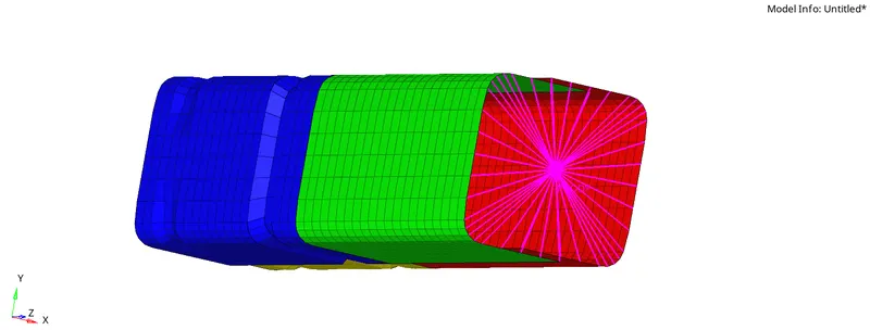
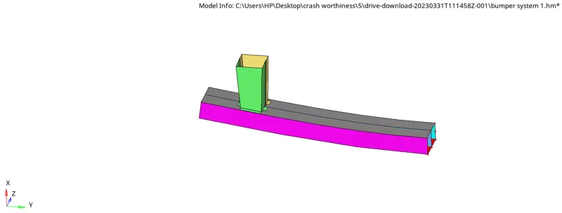
PROCEDURE
Meshing of a bumper model
- Open the hyperworks software.
- Select "import geometry" option and also set the file type format, then import the first model.(import geometry>model>open)
- Do the geometry clean up by toggle edge where the minimum length criteria fails.(Geometry>quick edit>toggle)
- Give mesh size as 6mm in auto mesh panel.
- Select the surfaces and mesh by using automesh tool.(2D>automesh>select surface>mesh).
- We can adjust the no of nodes on the edges by right click/left click and give the good mesh flow
- Check wheather there is any free edges present within the body (Tools>edges)
- If there is any free edge present mesh fix it by using replace points(F3)
- The meshed model is given below
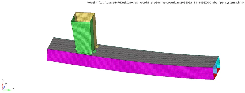
Solving different cases of crashtube
Case 1:
- Import the model by using solver deck tool.
- Here we are importing starter file.
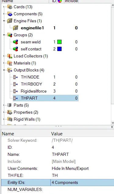
- In order to create the THPART we have to click on the output Blocks and create the TH PART , in entity id instead of nodes keep components and select all four components and click on ok. Then the TH part is created.
- The base simulation is run without any modification to element properties using Radioss option under Analysis tab.(Analysis>radios)
- Create a folder to save the rad files in local directory and edit options providing number of threads as " -nt 4 ".

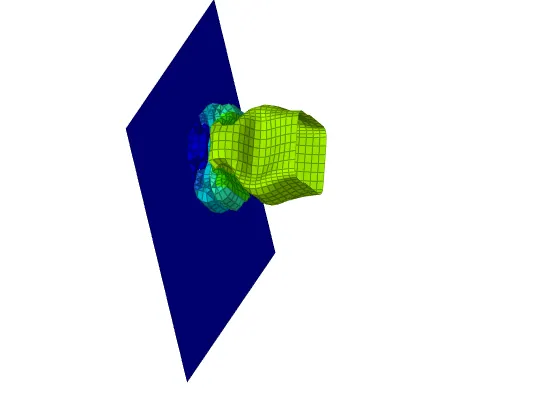
- After analysis, the .OUT file is viewed to check whether the Energy error and mass error fall within the aceptable range
- The energy error starts from 0% to 10% which is within acceptable range. Mass error stays constant throughout the simulation

- Since the error values are acceptable,internal energy,contact energy, Rigid body forces of the simulation are plotted with the help of hypergraph 2-D.
- Hyperview is opened to view the simulation . model and results (h3d file) are loaded from the newly created folder.
- Animation shows how the forces affect on the model and simulate the crash propogation.
- To plot the specific graphs, hyper graph 2-d is selected.
- File named end at T01 is opened and specifies energies are plotted against time
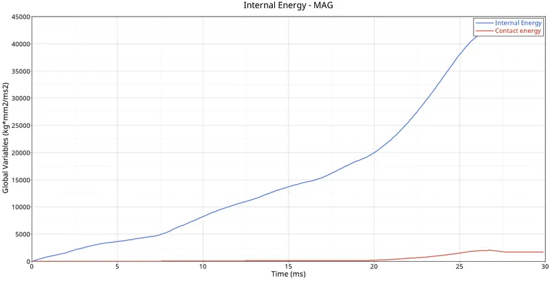
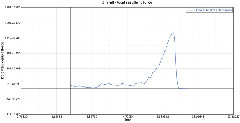
- From output file energy error is -3.8%% and mass error is 0% which is less than -15% to 2% and 1% respectively, so we can accept the results and plot the graphs by using hypergraphs
- Contact energy = contact force* distance moved to avoid penetration it is the energy which enables contact force to avoid penetration.
- Internal energy increases with time because of the impact and contact force also increases and than decreases due to impact.
- There are some variation in contact energy in some places.
Case 2:
- Import the model by using solver deck tool and change inact=6.
- After changing the parameters run the simulation with same steps to be carried as per previous case. The simulation is shown in GIF below. Plot the graphs of energies same as above case.
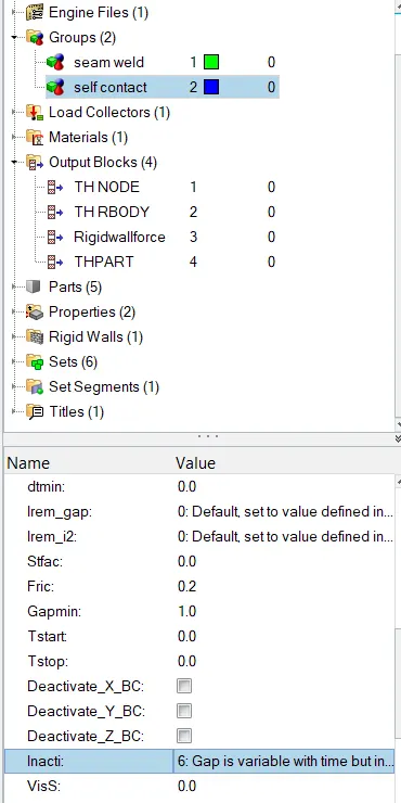
- Plot the graph for internal energy,contact energy and rigidbody force.
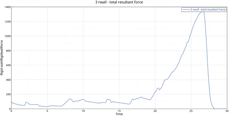
- The Internal energy for the components is increasing at the beginning because it is attached to the rigid wall and deform smoothly from the notch area where as the stiffness is less at this part.
- The contact energy is varying at a very small amount at the beginning and there is a sudden peak formed because there is large amount of energy developed at the end of deformation.
- Rigid body forces are high at the time of impact then it is decreasing.
- From output file energy error is -3.8%% and mass error is 0% which is less than -15% to 2% and 1% respectively, so we can accept the results and plot the graphs by using hypergraphs
Case3 :
- In this case, we have to create Type11 contact and run the simulation.
- for this we will implement type 11 interface with below criteria
Istf:4
Igap:1000
Stmin: 1
Fric:0.25
Gapmin:0.45
Inacti:6 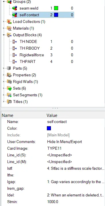
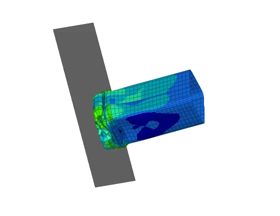
- Plot the graphs.
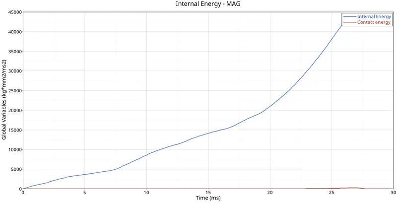
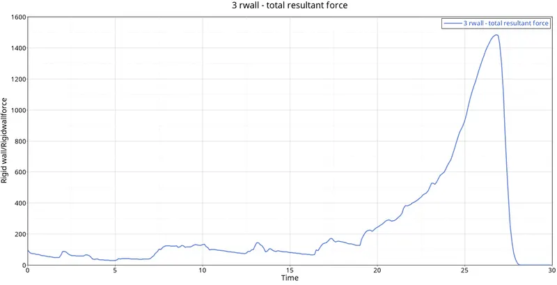
- Type 11 contact interface is used here. It is a surface to surface contact interface.
- Here too, the nature of deformation and energy graph nature are similiar as previous case. The notched portion is first to deform. Energy error is about -3.8% which is acceptable.
Case 4:
- Remove both notches and remove boundary condition on rigid body node then run.
- To remove the boundary conditions on the rigid body, go to Solver > BCS > rbody_12456
- For this go to delete option and delete the notch area elements and create new ones by using rule option(2D>Ruled)
- Run the simulation.
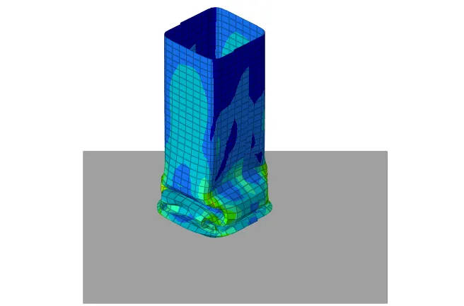
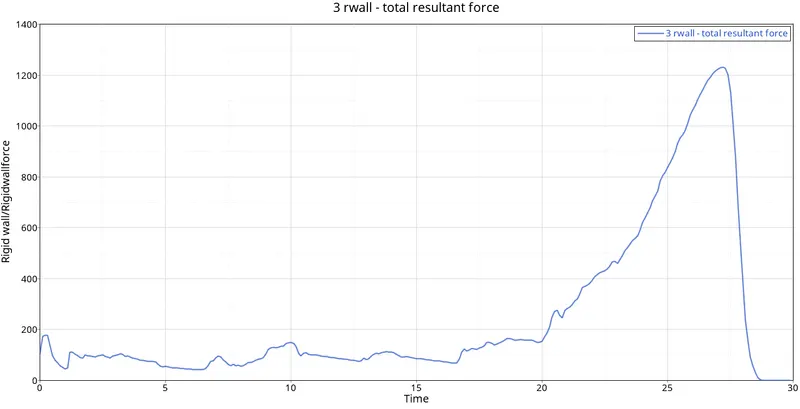
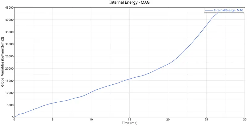
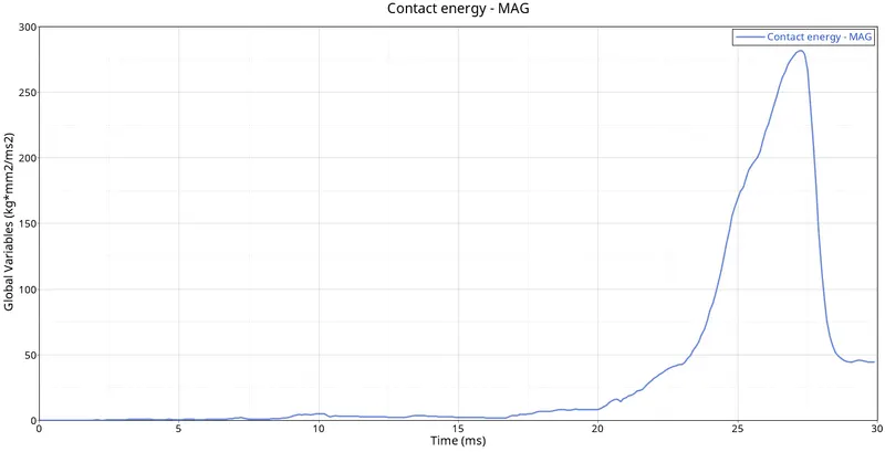
- The Internal energy for the components is increasing at the beginning because it is attached to the rigid wall and deform smoothly there is notch on the middle opposite 2 surface whereas the stiffness is less.
Case 5:
- In this model we are going to create a new notch in the middle ,select the whole section and run.
- we can use case 4 model for this purpose.
- For this we can use translate tool in hypermesh.(Tools>Translate)
- Run the simulation with given criteria.
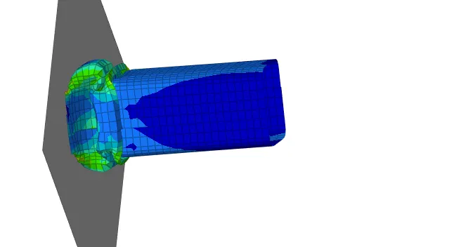
- Plot the required graph
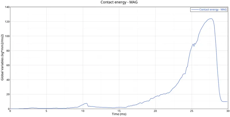
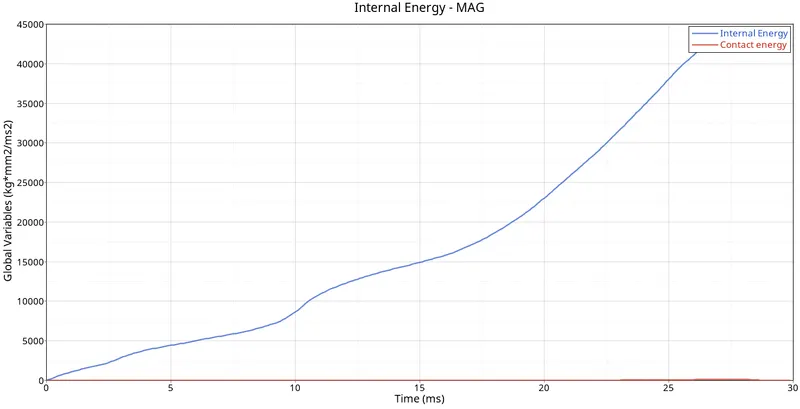
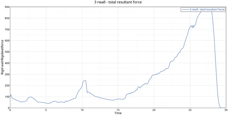
- Internal energy increases with time because of the impact and contact force also increases and than decreases due to impact.
Case 6:
- Create notches on two opposing surfaces and run the simulation. The procedure to create notch is the same as discussed earlier using Translate tool.
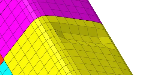
- Run the simulation.
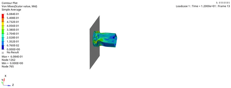
- Plot the required graphs.
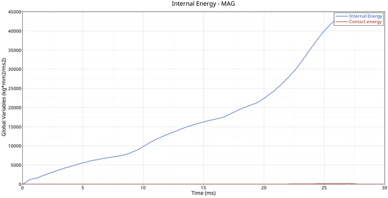
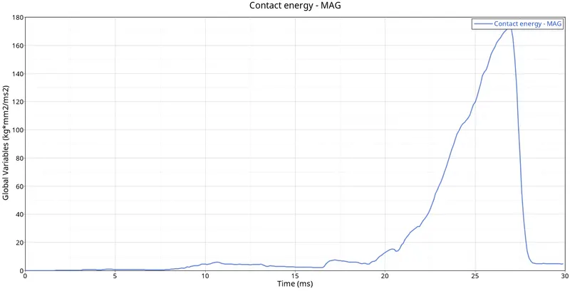
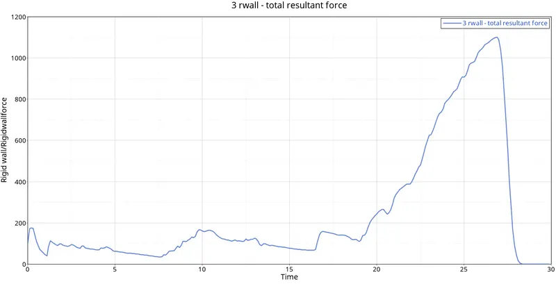
- Here too the nature of deformation and energy graphs nature is similar to the previous case. The value of contact energy is more as compared to the previous case because of the presence of notches in the middle.
- When objects collide, contact forces transfer energy so as to change the objects' motions. When two objects interact, each one exerts a force on the other, and these forces can transfer energy between them
CONCLUSION
- In case 2 Inacti =6 is applied but the nature of energy graphs remains the same which indicates there was no initial penetration.
- Von mises stress value is least in case 4 where notches are removed.
- Energy error for all the cases is in the acceptable range.
- In the fifth case, energy error is maximum due to the notch created at the middle section. In the sixth case, it is reduced due to notches created at the opposite faces.
- The notch areas have high stresses and deform first. In the plane surface where the notches are removed the stress levels are low. Hence, we can state that by removing the notch helps to reduce the stress acting in the body.