Assignment 2-RADIOSS Engine File Editing & 3D Meshing Challenge
AIM
- Check the material properties of the rail component and calculate the speed of sound in steel rail
- . The length of the rail is about 1000 mm.calculate the time takes for a shock wave to travel from one end of the rail to the other.
- Time for sound to travel length of rail
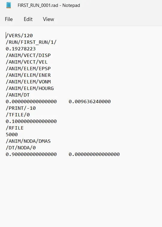
- .Edit the engine file so that the stress wave can be monitored, moving from one end of the rail to the other during impact -this will require a termination time equal to the time it takes for the sound to travel the length of the rail(set on/RUN card)
- Set the frequency of animation output to a time that will give 20 animation steps(/ANIM/DT)
- Change /print -10.
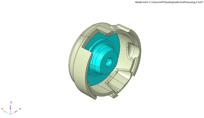
3d meshing tetra mesh and hex mesh
- Repeat class examples and, maintain the quality.
- Target tet size=5mm,hex size=10mm,tet collapse=0.15.
MODEL
PROCEDURE
importing the FIRST_RUN_0000.rad
- Open the hypermesh in radios block.
- First, we have to check the material properties of the rail component.
- There are two multiple ways to check the material properties. One of the ways is to import the file in Radioss and check for the material properties. So after opening the Hypermesh, we will choose our user profile as RADIOSS.
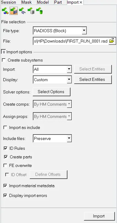
- Then we will import the starter file in Radioss.
- In our case, the given file name is FIRST_RUN_0000.rad, we will import this file under Import Solver Deck browser as shown below
- check the material properties in the model.We can find yougs modulus and density from the status bar.
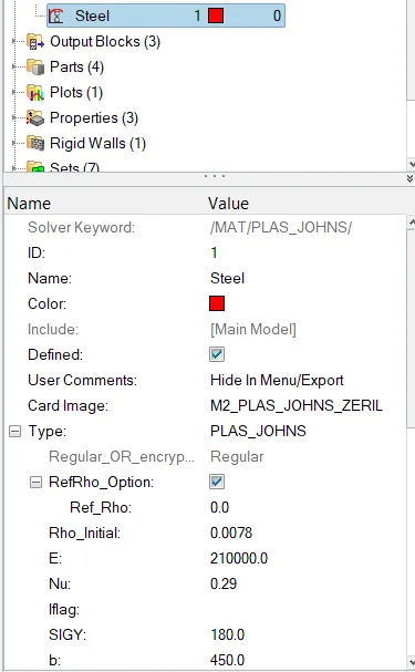
Now to calculate the speed of sound in steel rail, we have the following formula,
c=√E/rho
Where, c is the speed of sound, E is Young’s Modulus, and ρ is density
- Apply the above equation with values.
c=√(210000/0.0078)
=5188.75 m/s
- Calculate time taken for shock wave to cross the rail of 1000mm
Formula for time taken t=l/c
t=1/5188.75
=0.1927ms(milli seconds) Set the frequency of animation output to a time that will give 20 animation steps(/ANIM/DT)
frequency=(l/c)*time
=(1/0.1927)*20
=.oo963624Hz
- Open the FIRST_RUN0001.rad file as textfile and edit the values to above calculated values.
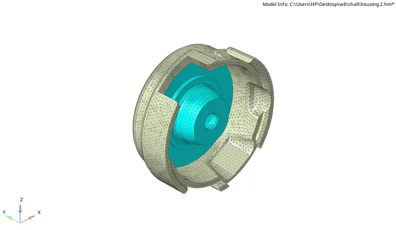
Tetramesh of housing component
- First Import the housing model.
- Select "import geometry" option and also set the file type format, then import the first model.(import geometry>model>open)
- we have to clean up the given model by removing the holes and unfilled surfaces (Geometry>quick edit>fill hole)
- Defeature the component where minmum ength criteria failed.(Geo>defeature)
- Toggle the edge where minmum length be failed and unwanted divisions and divide the model into different sections.(F11-Quick edit)
- After the geometry cleanup, go to 2D mesh menu and select automesh option, change the element size to 5, element type to mixed and select the mid surface and click mesh to generate the mesh.(2D>automesh>select surface>mesh)
- After completed the meshing awe have to check quality so shift the view into by element quality.For solid meshing mainly we check min length and max length.(F10)
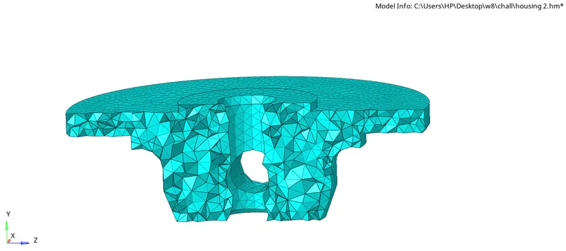
- After fixing the 2D Quality go to the tetra mesh panel and change the component to elements and select the all elements and proceed with mesh(3D>tetra mesh>select elements)
- We can set tetcollapse parameters. (3D>tetramesh>tetramesh parameters)

- After generating the tetra mesh check tetcollapse (F10>3D)
-
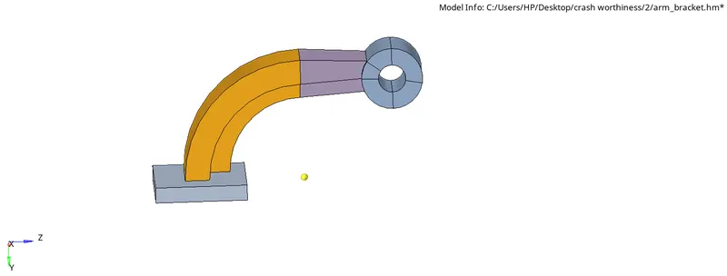
Hexa mesh of Arms_bracket
- First Import the Arms_bracket model.
- After importing the model in Hypermesh, we will look for surface defects in the model in order to perform Geometry cleanup.
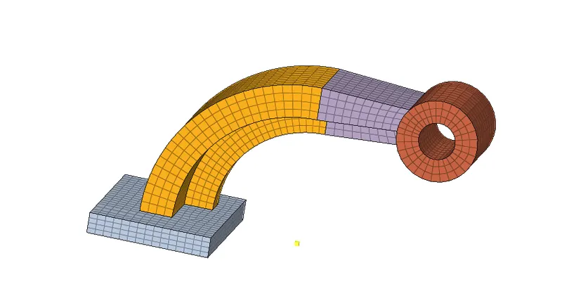
- As there were no surface defects in the model, we will proceed for meshing. There are four components in the model which are base, arm curve, arm straight and boss. So we will mesh them one by one.
- In hexa mesh we only use quad elements.First we have to mesh base so do the 2D mesh on top surface with quads only.
- We can use solid drag panel to create the 3D solid elements.Give the source elements and destination surface.(3D>solidmap)

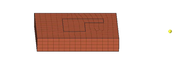
- Now, we will mesh the component connecting the base which is arm_curve as the base component has the imprint topology of arm_curve component.
- We will make it as our current component and hide all other components.
- Find the radius of arme component and extract the face to rotate along with the center by using face panel(Tools>face)
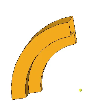
- rotate the elments along with center in 90 degree with 25 layers of elements.
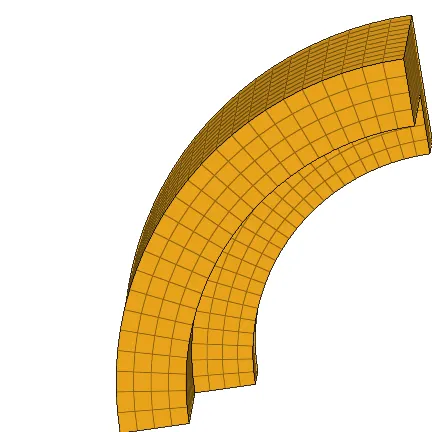
- Now, we will mesh the component connecting the arm_curve which is arm_straight. As this component has tapered geometry, we will perform linear solid command to obtain 3D mesh.
- We will need 2D elements or faces to create linear solid. So we will create faces from the 3D hexa elements of arm_curve component.
- We will navigate to faces panel in Tool page, where we will select the elements of arm_curve and then click on find faces. This will create faces on the arm_curve elements. On the other tapered surface of the arm_straight component.
- we will create 2D mesh in such a way that the nodes and elements are exactly corresponding to the opposite face
- Then we will go to linear solid panel in 3D page. Here, we will select from elements as the face elements present on the joining surface of both the components
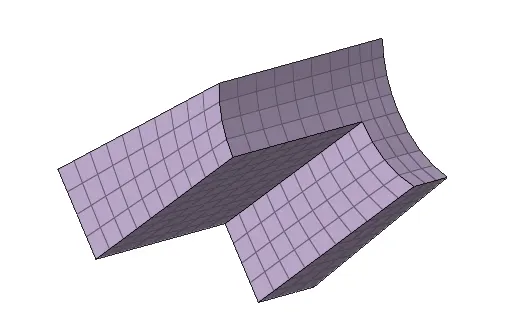
- Similarly do the same procedure that above mentioned to mesh other components
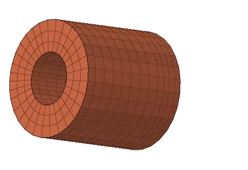
CONCLUSION
- The speed of the sound in steel and the time taken by the sound wave to travel through the length of the steel rail has been successfully calculated. These calculated values are given as the termination time and the frequency of the animation output in the engine input file by editing the .rad file directly.
- Then the two components (housing and arm bracket) are meshed using the 3D solid elements (tetra and hexa) with the required quality and mesh flow.