Assignment 6-Frontal Crash Simulation Challenge
AIM
Main objective of frontel crash simulation is to understand about the force recieved on each component of frontel car body and to know how a frontel crash simulation runs in radios solver.
Frontal crash-BIW
- Check unit system and either follow[Mg mm s] or [Kg mm ms].
- Create appropriate interface ,friction 0.2 and recommended parameters.
- Make sure of no penetrations and intersection.
- Correct rigid bodies if any issues.
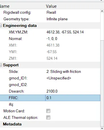
- Create rigid wall with friction 0.1.
- Compare the model weight with the full scale 300k nodes model and use added masses to reach target weight 700kg while getting CG about the required range.
- Initial velocity 35 mph.
- Use model checker to ensure good quality.
- Time-step :0.5 to 0.1 microseconds.
- Run 80 ms.
Output requests:
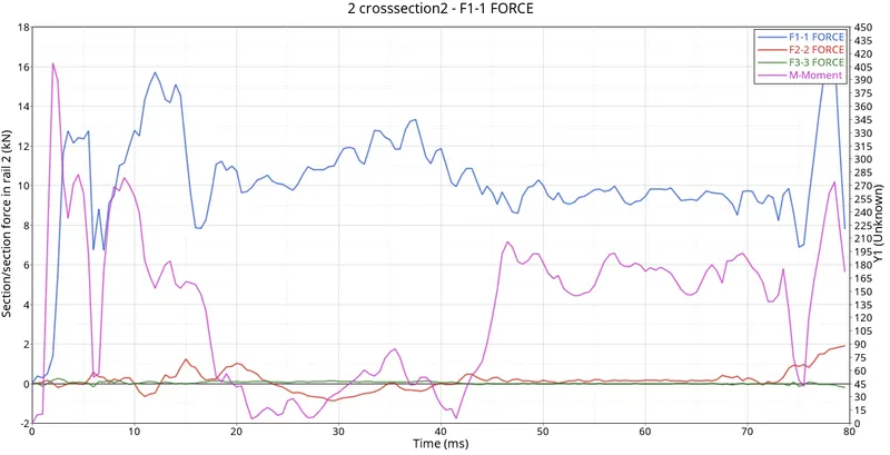
- Sectional force in the rails at location of indicated node 174247.
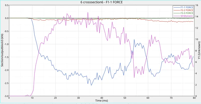
- Axial force received on the rails from bumper.
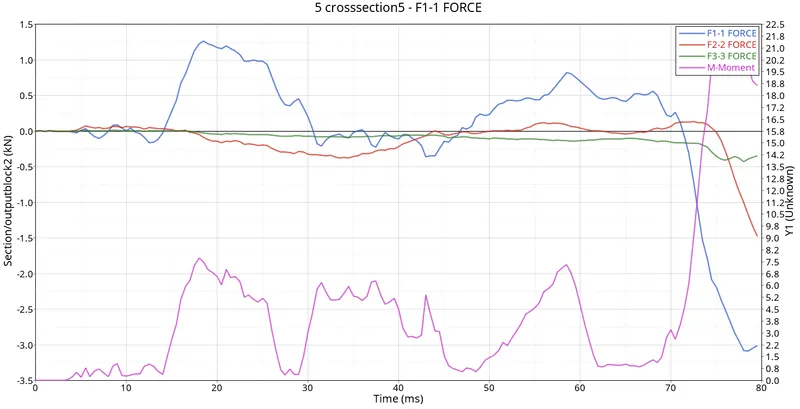
- Shotgun cross sectional forces.
- A pillar cross section.
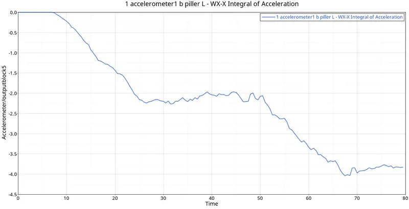
- Acceleration curve received on the accelerometer at base of B pillar (on B pillar rocker).
- Intrusions on the dash wall 66695,66244.
MODEL
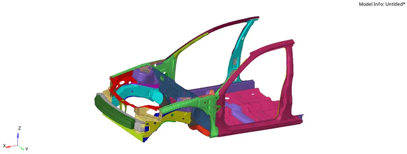
PROCEDURE
- Open the hyperworks software.
- Import the solver deck file in the hypermesh in radios format.
- Here we are importing starter file
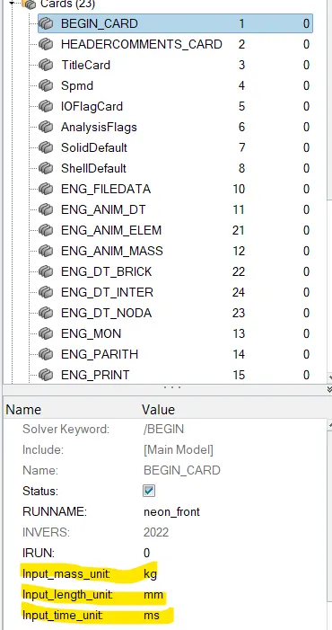
Check unit system and either follow[Mg mm s] or [Kg mm ms].
- To check which unit system follow the procedure Model > Cards > BEGIN_CARD.
Create appropriate interface ,friction 0.2 and recommended parameters.
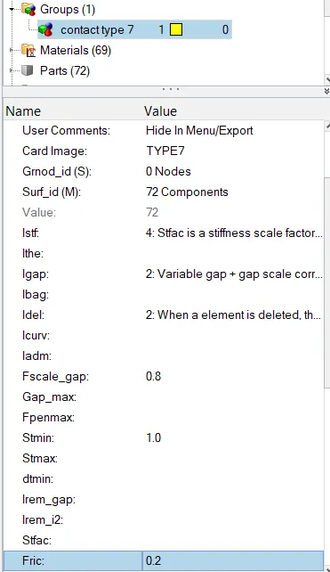
- Next step is to create Interface contact for the car model. Inerfaces are defined to model how parts interact when they come into contact with each other.(Right click>create>Interface)
- Here we are using type 7 (node to surface) interface and add appropriate parameters.
- Select all the components in surface ID.
penetrations and intersection
- Penetration check is used to check wheather any components are intersected or penetrated with each other.
- To check penetration go to Quality>Check intersection of tree selection>include picked parts >select the components by box selection>Right click.
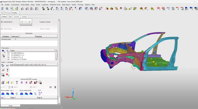
- There is no penetration or intersection in this components.
Create rigid wall with friction 0.1
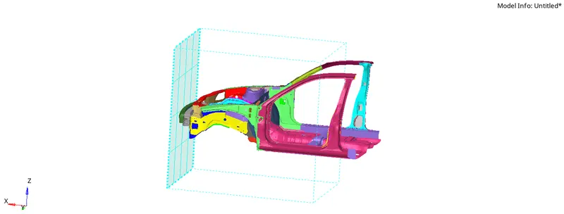
- Rigid walls allow for an easy way to define a interface between a rigid surface and nodes of deformable body.
- To create go to Solver Deck > Right click > Rwall > plane.
- Give sliding friction 0.1 and select any node on the bumper and change the x-coordinate such that a gap is maintained.
- Give search distance as 2500mm.
- The model with rigid wall is shown below
Mass Balancing and COG
- Import the file in hypercrash and go through Mass>Balancing.
- Now we can see total mass and some added mass in the list.
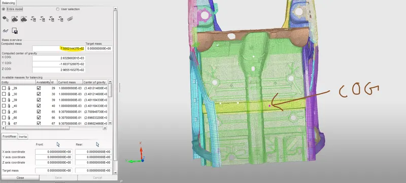
- Identify the COG in the car body.
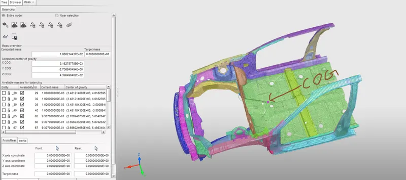
- From the above dialog box we can find that total mass of the frontel body is 188 kg. We have to add mass upto 700kg.
- Make sure position of COG is under the driver seat.If it is not make tham into proper position by adding mass.(Loadcase>Added mass)
- Create add mass and add mass by selecting the required nodes. Generally we are assigning the mass in whole of group of nodes.
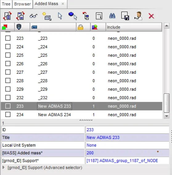
- We have to add further 512 kg. Here we are creating two add mass and assigning mass until COG comes into proper position.
- After adding mass we need to export the file andimport it in hypermesh.(File>Export>Radioss)
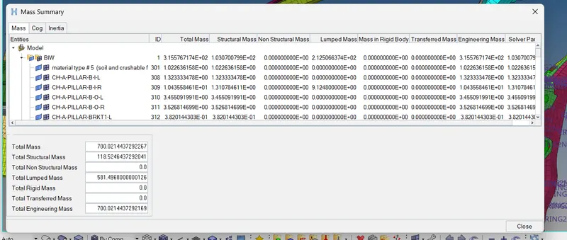
- Check the mass details in hypermesh.
Initial velocity
- The velocity input for this simulation as per the Standards is 35mph so when we convert it to m/s the input velocity is 15.6464m/s.
- To create a velocity Go to solver browser >> Create >> boundary conditions (BC) >> Inivel
- Define the Node group on which specified initial velocities are applied (grnd_ID1). For our simulation, we will be selecting the whole vehicle setup.
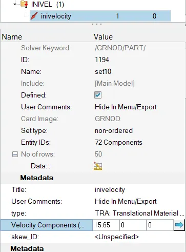
- The velocity type is selected as Translation velocity and it is provided in the x-direction as shown in the above image.
- change the time into 1ms
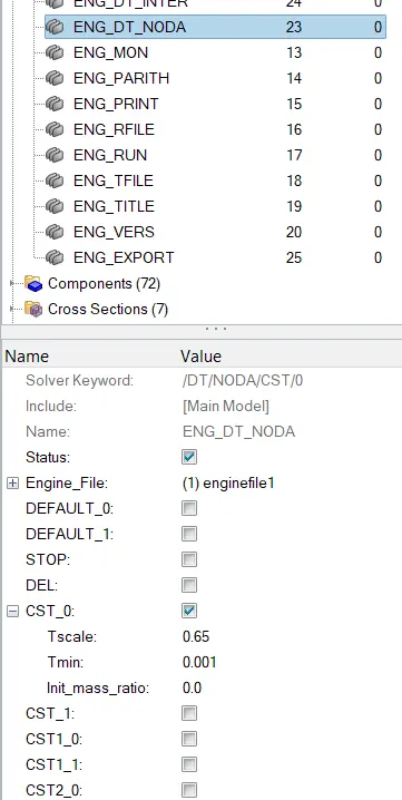
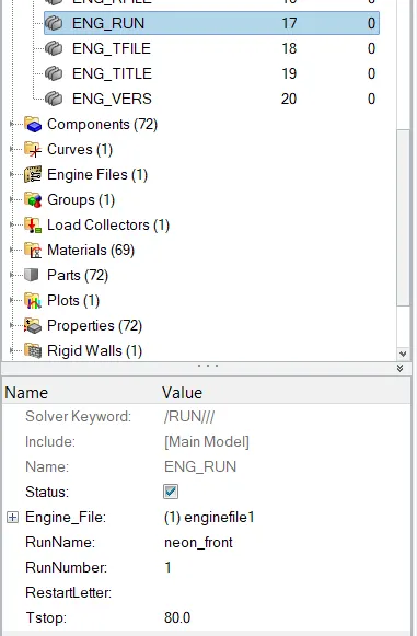
- Change the engine run time into 80ms.
Creating Sections
- We are going to create Sections at A-Pillar, Shot Gun, rails, and the Bumper in order to Study the sectional forces
- We have to know how the forces are transmitted from the Bumper to the Dashboard and the rate of deformation. It is done in order to ensure the safety of the passenger.
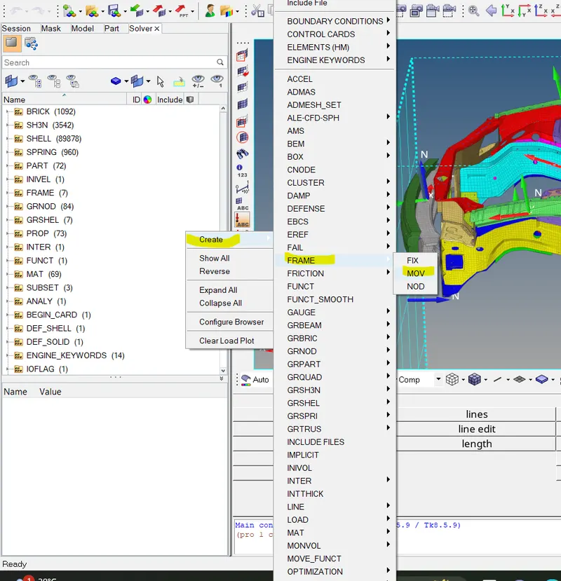
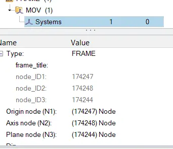
- We are using these moving frames to create a section as shown below.(Go to solver deck>Right click>create>Frame>Mov)
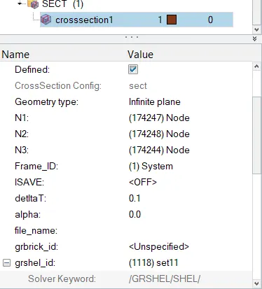
- To Define sect Go to solver deck>Right click>create>Sect
- Define the Nodes with reference to the Axis of the Frame.
- Enter the values of Delta T as 0.1
- Define the cutting plane by a group of elements and its orientation by a group of nodes (grshell_ID)
- Hence, the sections will be created.
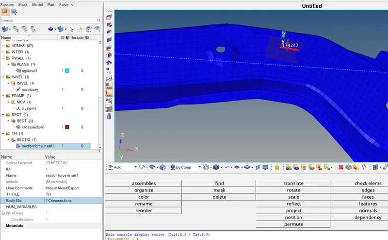
- The next step is to create TH card for requesting the outputresult.(solver deck>right click>Create>TH>Sect)
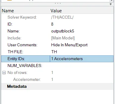
- Define the entity id and variables in TH card.
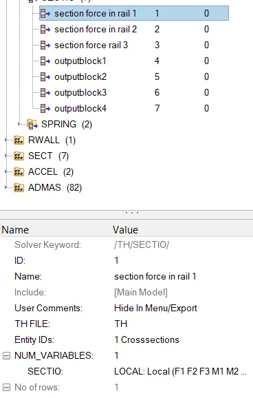
- Do the same procedure for creatind section in A-Pillar, Shot Gun, rails, and the Bumper
Creating accelerometer at base of B pillar
- An accelerometer is a basic technology that converts mechanical motion into an electrical signal. It is an electromechanical device that measures acceleration forces, whether caused by gravity or motion.
- To create accelerometer Go to Model browser >> Create >> Accelerometer >> Select Node_ID >> Select node >> Proceed
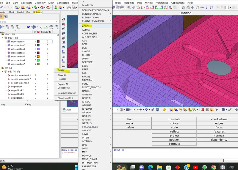
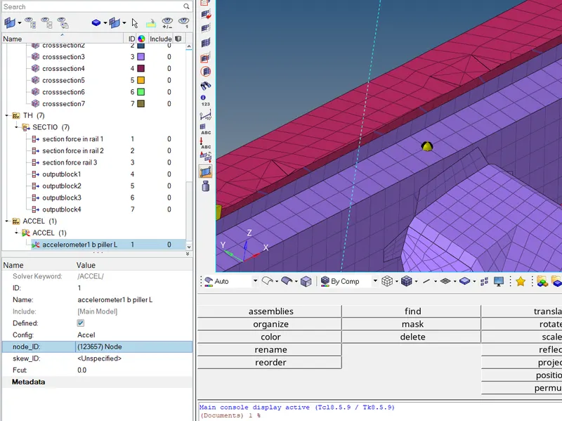
- Make sure to create a Time History file for these Accelerometers Individually so that we can view the intrusions.
Intrusions on the dash wall 66695,66244
- We are planting spring elements to study the intrusions (forces inside the cabin causing deformation/rupture).
- Create 2 parallel spring elements from the indicated nodes (66695, 66244) till the Crossbeam.(1D Panel > Springs )
- We have to provide the springs with their respective properties.Go to model Browser > Create >Property >Rename as Springs
- After creating a property, a new tab will open there we have to select CARD image as P4 SPRING and Mass as 0.001, and Stiffness as 0.001 and assign all these properties to the spring.
- Make sure to create a Time History file for these Springs Individually so that we can view the intrusions.(solver deck>right click>Create>TH>Spring)
Model Check
- The Model checker will give us any warnings and Errors regarding the model definition , the boundary and Kinematic conditions.(Tools>Model checker>Radioss)
- We can clear it by using autoclean up.
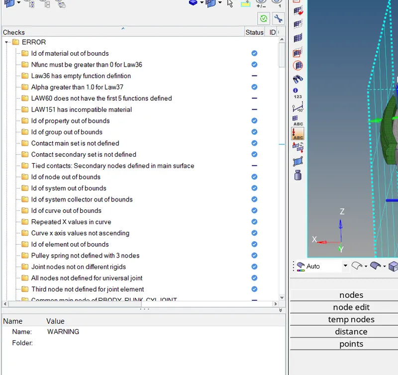
- After applying all the boundry condition and Kinamatic condition , we have to run the analysis (Analysis >> Radioss >> Input File (File Location) >> Radioss)
RESULT
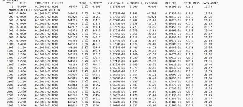
- The Energy Error is Negative and has been linearly increasing up to -1.8% only, which is acceptable. Mass error is very low which is acceptable We can conclude that the simulation is good.
- Plotting the energy curves using Hypergraph 2-D with the help of T01 File
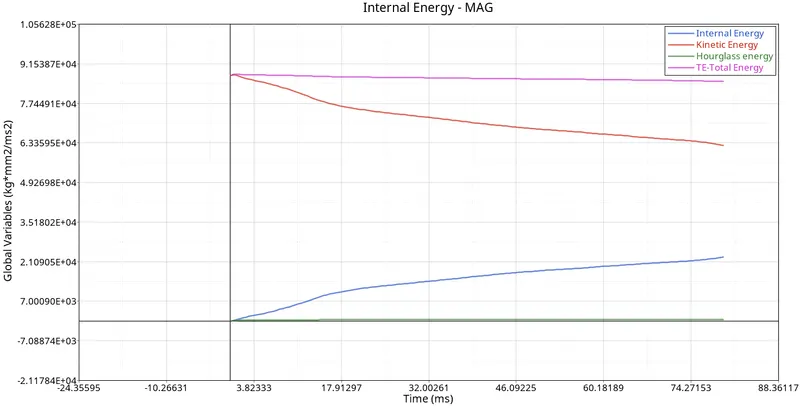
- It is observed that there is an increase in the internal energy in the model with the progress in simulation. With the increase in Internal energy, there is a proportional decrease in kinetic energy in the model. Hourglass energy remains negligible throughout the simulation. So Totel energy is constant throughout the simulation.
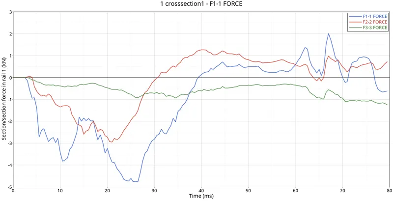
Sectional force in the rails at the location of indicated node 174247.
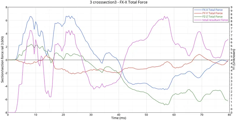
Axial force received on the rails from the bumper
Shotgun cross-sectional forces
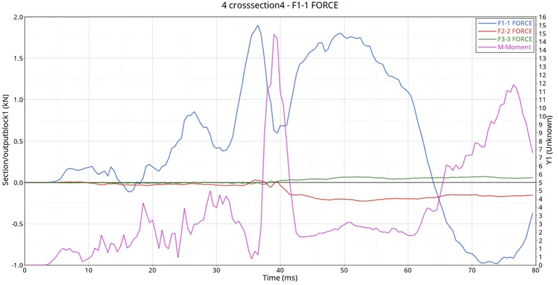
A-pillar cross-section
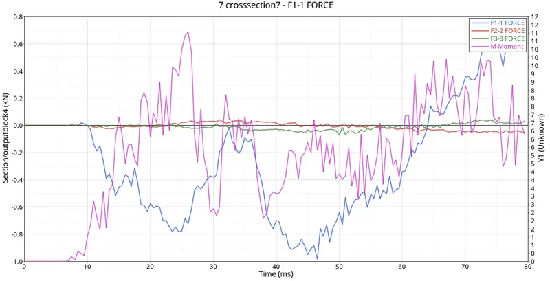
Acceleration curve received on the accelerometer at the base of B pillar (on B pillar rocker)
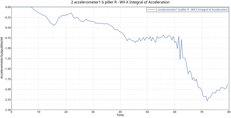
Intrusions on the dash wall 66695
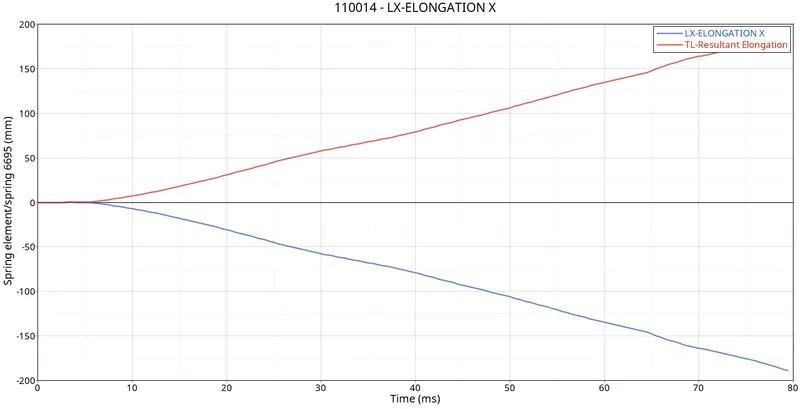
Intrusions on the dash wall 66244
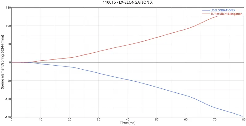
- It is observed that, there is a maximum Elongation of about 148mm on the 66244 node and 189mm the on 66695 node.
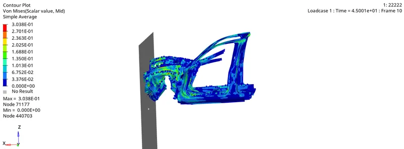
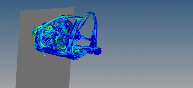
- Simulation shows that the forces due to the crash is distributed throughout the model components with very less stress concentration at specific locations.
- Initially bumper deforms, then the forces are transmitted through rails to the rest of the model components. The front part of the model gets lifted due to the crash which shows the real-life scenario to a certain extent
CONCLUSION
The given frontal crash model is analyzed for a frontal crash scenario and the requested output aspects are observed.The forces and energy curves at the specified locations are observed.