Week 4-1D Element Creation Challenge
OBJECTIVE
Mesh the Given component with the Size of 5 Units. Create 1D elements on the following component with given cross-section and DOF
a. Rod element:- Translational DOF should be Constrained with RBE2 link
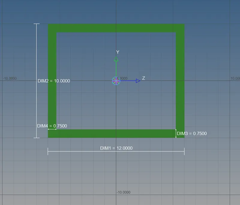
Cross-Section: BOX- Dimension a= 12 mm
dimension b=10 mm
Thickness t= 0.75 mm
b. Beam element:- All DOF should be constrained with RBE3 link
Cross-Section: I Section- Dimension a= 8 mm
Dimension b= 10 mm
Dimension c= 8.5 mm
Thickness t1= 0.75 mm
Thickness t2= .6 mm
Thickness t3= .6 mm
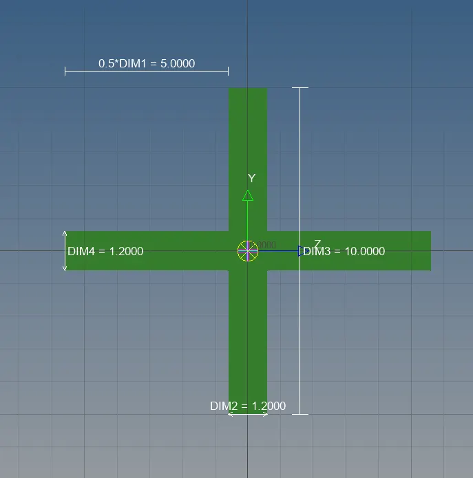
c. Bar element:- Constrain only x and y DOFs With RBE3 link
Cross-section: X section- Dimension DIM1= 5 mm
Thickness DIM2= 1.2 mm
Dimension DIM3= 10 mm
Thickness DIM4= 1.2mm
d. & e. Apply the mass of magnitude 10 with the RBE2 link
f. Join the two components with Spring elements
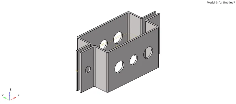
CAD MODEL
PROCEDURE
- Open the hyperworks software.
- Select "import geometry" option and also set the file type format, then import the " Rear truss mesh" file.(import geometry>model>open)
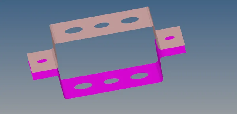
- Generate the midsurface of upper part of bracket using midsurface tool in geometry(geometry>midsurface>select the surfaces >extract)
- Follow the same procedure to extract the midsurface of lower part of bracket.
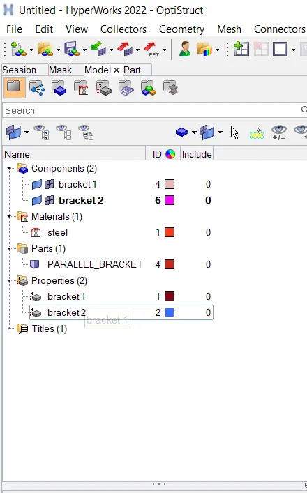
- Assign the saperate properties for upper and lower part of midsurfaces.(right click on tab bar>create>component)
- And also create material for the bracket.Here steel is used as the material of brackets.(right click on tab bar>create>material)
- Delete the solid components from components list
- Create washer split around pin hole areas to obtain cleaner mesh flow.(geometry>quick edit>washer split of size 5mm)
- After this process we need to mesh the model.So go to mesh module and give element length 5mm and mesh the model.(2D>automesh>select surfaces>mesh)
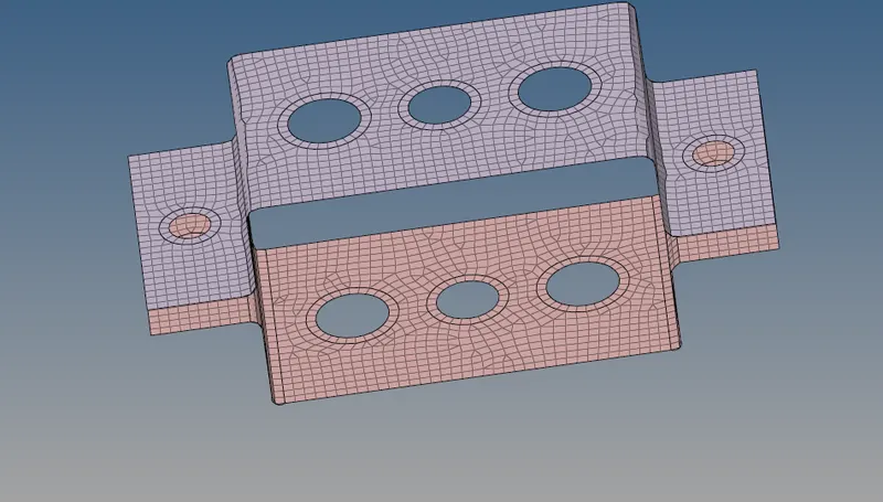
- Arrange the no of nodes in washer area and clear the mesh flow.
- Next step is the creation of 1D elements that is specified in the question
- RBE-2 connections are mainly used for rigid connections.In this type of connection loadis equally distributed.(1D>rigid>select nodes>create)
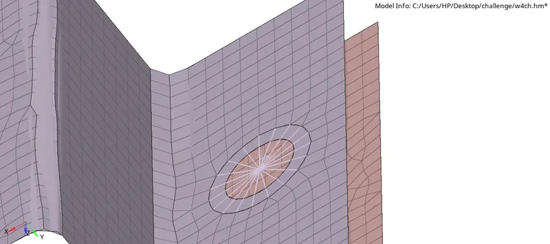
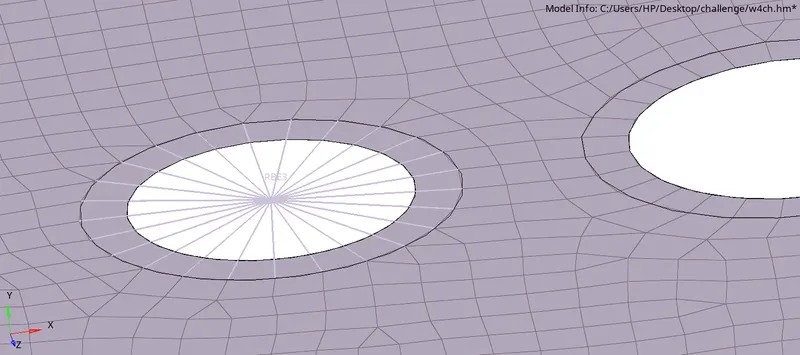
- In RBE-3 connections load is unequally transmitted through the nodes.(1D>rbe3>select nodes>create)
- Constrained the DOF as per mentioned in the question.
- Create rod element by using hyperbeam option .(1D>hyper beam>standerd section>optistruct>BOX)
- In new window shows the dimension of the rod element .give the dimensions.
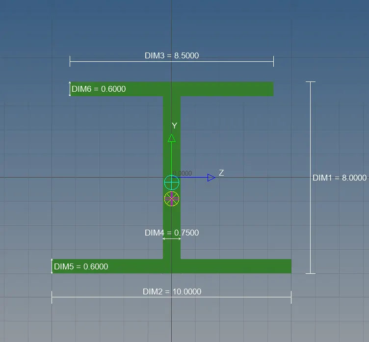
- Create beam and bar elements by using similar steps thatis mentioned above.
- Create the properties for rod,beam and bar elements and assign beam sections and card id
- Create connection of rod between two nodes(1D>rod>select nodes and give property>enter)
- Similar procedure for beam and bar give properties
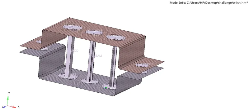
- Add mass elements on specified area(1D>Mass>create)

CONCLUSION
Extract the mid surface from given model and assign the properties and material for the given model.Meshing of the given model is succesfully completed.
Created the 1D elements for required area.