Project - 2 - Meshing on the suspension Assembly
AIM
For the given assembly, check for the geometrical errors and mesh with the given element Quality criteria. After meshing the component the thickness has to be assigned for mid surfaces. Use tetra elements to model non-uniform thickness components. Also use Appropriate connections to connect the component.
Quality Criteria for Surface Meshing of Tyre and Rim (Element type: Tria) :
|
S.No |
Quality Criteria |
Value |
|
1 |
Target/Average length |
6.5 |
|
2 |
Minimum Length |
5 |
|
3 |
Maximum Length |
10 |
|
4 |
Skewness |
45 |
Quality criteria for Surface Meshing of Non Uniform thickness components other than Tyre and Rim (Element type: Tria) :
|
S.No |
Quality Criteria |
Value |
|
1 |
Target/Average length |
4 |
|
2 |
Minimum Length |
2 |
|
3 |
Maximum Length |
6 |
|
4 |
Skewness |
45 |
Quality Criteria for Volume meshing of all Non Uniform thickness components (Element type: Tetra Elements):
|
S.No |
Quality Criteria |
Value |
|
1 |
Tet-collapse |
0.2 |
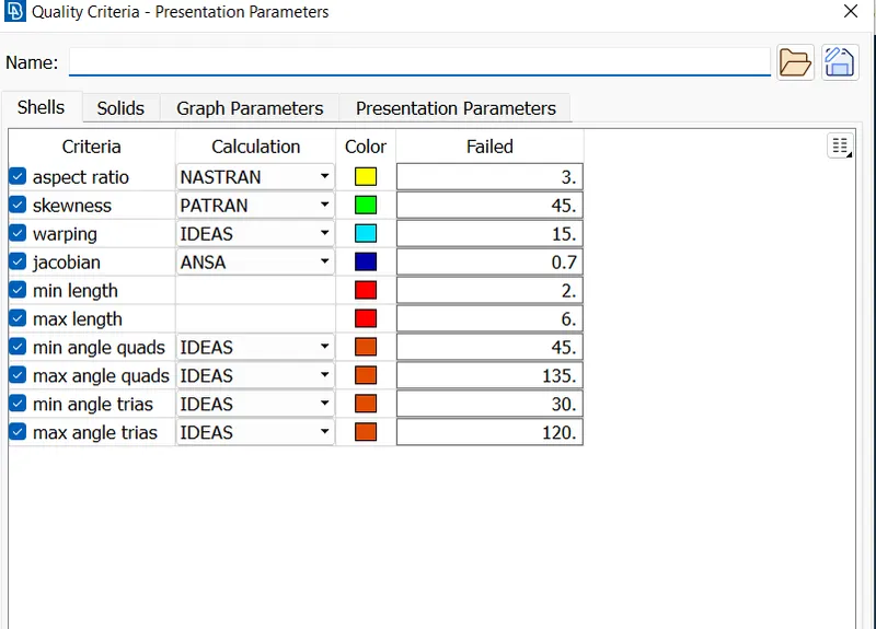
Quality criteria for Mid surfacing of Uniform thickness part which has thickness less than 5 mm (Element type: Mixed elements) :
|
S.No |
Quality Criteria |
Value |
|
1 |
Target/Average length |
4 |
|
2 |
Minimum Length |
2 |
|
3 |
Maximum Length |
6 |
|
4 |
Aspect |
3 |
|
5 |
Warpage |
15 |
|
6 |
Skewness |
45 |
|
7 |
Jacobian |
0.7 |
|
8 |
Minimum Quad Angle |
45 |
|
9 |
Maximum Quad Angle |
135 |
|
10 |
Minimum Tria Angle |
30 |
|
11 |
Maximum Tria Angle |
120 |
INTRODUCTION
The suspension of a car is actually part of the chassis, which comprises all of the important systems located beneath the car's body. These systems include
The frame : structural, load-carrying component that supports the car's engine and body, which are in turn supported by the suspension
The suspension system : setup that supports weight, absorbs and dampens shock and helps maintain tire contact
The steering system : mechanism that enables the driver to guide and direct the vehicle
The tires and wheels : components that make vehicle motion possible by way of grip and/or friction with the road
So the suspension is just one of the major systems in any vehicle.
PROCEDURE
- Import the suspension assembly model in ANSA Preprocessor and check each part of the assembly separately.
- The given model should be analysed properly and the model can be disassembled with the help of properties for better understanding.
- Check the geometry by using check manager for each part.In geometry clean up shows the errors includes single cone,crack,triple cone etc. (check>geometry>execute)
- Fix the errors that shows in geometry check up.
- Remove the triple cones and unwanted hot points and apply topo to whole geometry.
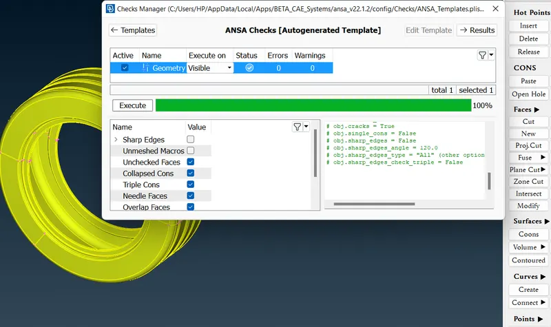
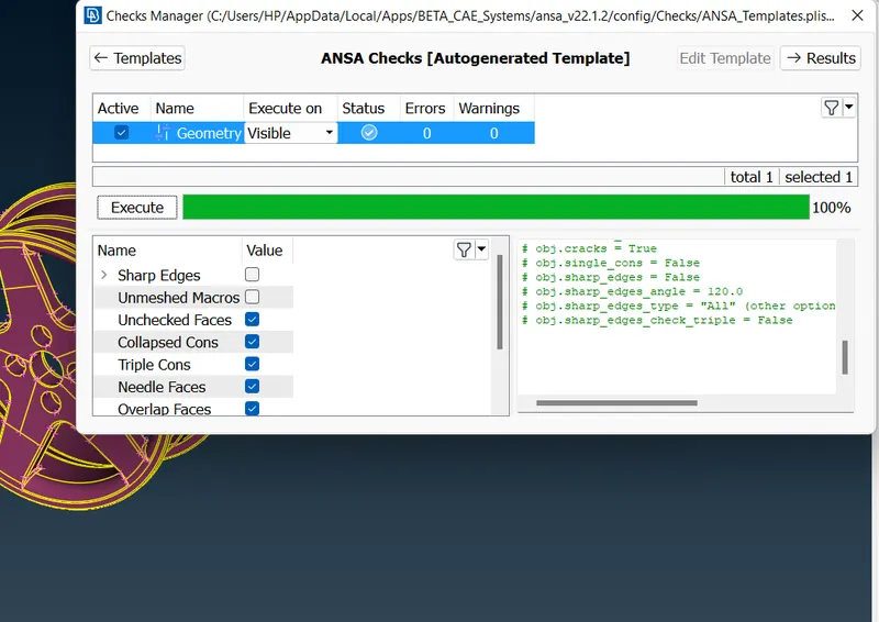
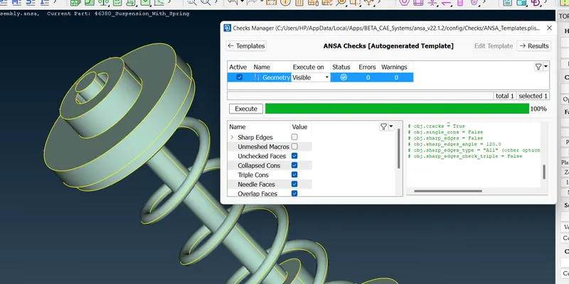
- Check all other components similarly.
- Here in this model there are many for solid meshing and some for mid surface meshing.
- Solid meshing used in models having thickness greater than 5mm and solid models but Mid surface meshing used in plastic components(below thickness 5mm).
- There are two types of solid meshing. 1. structured mesh :In this meshing contains quads and hexa elements.it has specific pattern and growth rate.
2. unstructured mesh :In this meshing contains tetra element only and it has no any specific pattern. - Here we use unstructured mesh.In solid meshing we need not generate mid surface so first step is to give quality criteria.
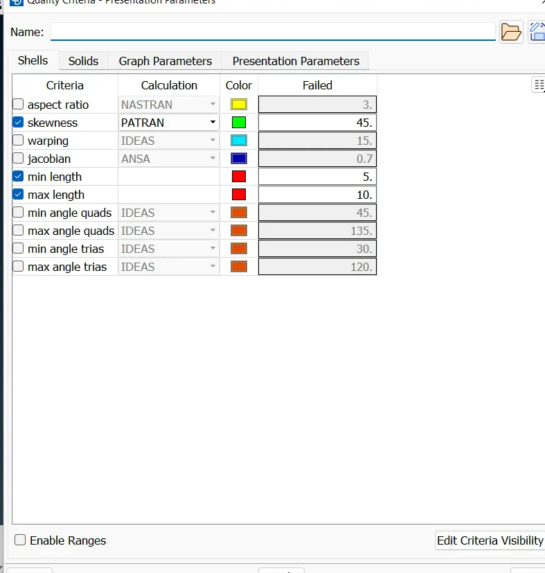
quality criteria for Tyre and Rim
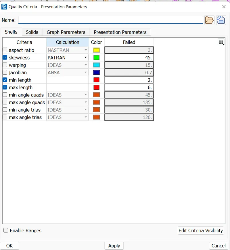
quality criteria for other solid parts.
- Apply mesh parameters by giving target length and minimum length and tria elements.
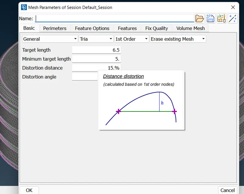
Mesh parameters for Tyre and Rim
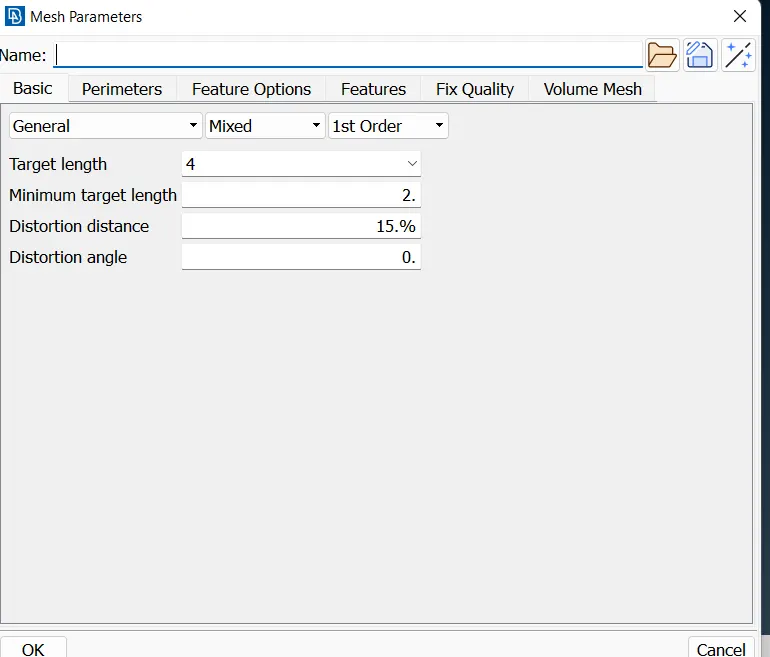
Mesh parameters for other solid parts.
- Now we need to mesh the solids.So we go through the steps mesh>classic mesh.
- Here we use Batch Mesh for mesh all the surface together.(Tools>Batch Mesh).
- create new mesh scenario and select each components
- Select the contents from the model browser by double click on the contents.
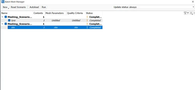
- Give quality criteria and mesh parameters on each row and select the component and give run.
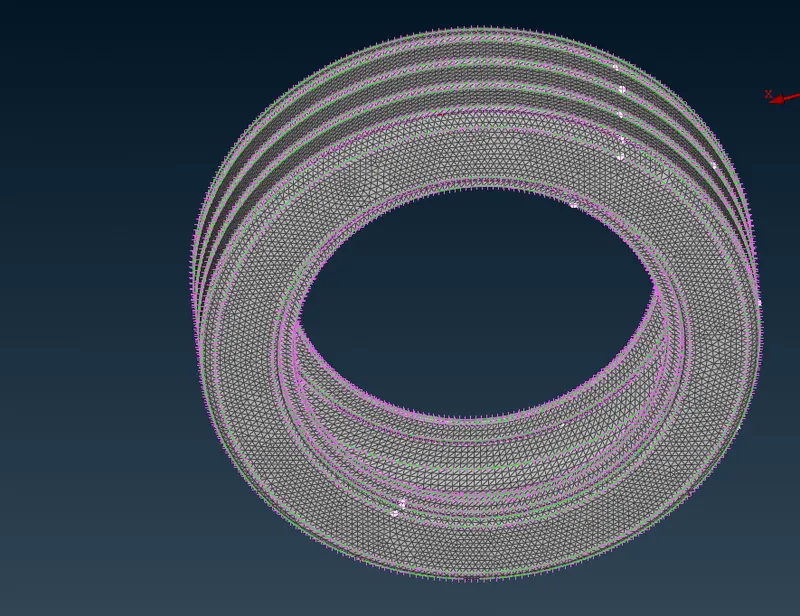
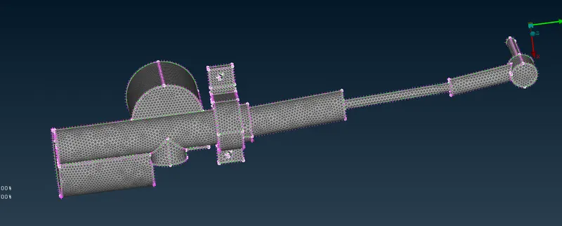
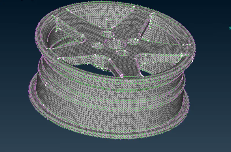
- In mesh flow there are some failure in quality criteria.By using Reconstruct,smooth tools fix the area.(classic mesh>shell mesh>improve)
- After the surface meshing next phase is volume mesh.we can go through the following process mesh>volume mesh
- Volume meshing is the process of giving the volume for the given model.
- Next step is define the volume by using the tool define in volume mesh (mesh>volume mesh>define)
- ANSA automatically detect the model and define in the list.
- we can edit the properties in the list and add the mesh algoritham (mesh>volume mesh>list)
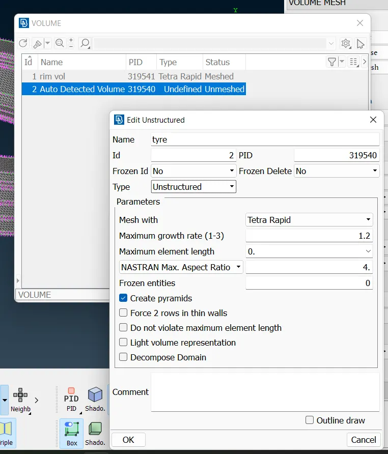
- remesh the given bodies with Tetra FEM/Tetra Rapid algoritham(mesh>volume mesh>list>remesh)
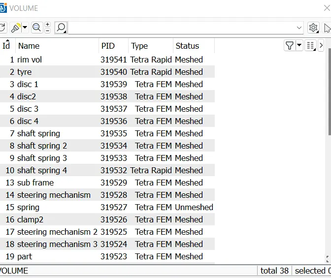
- After the volume mesh enable the collaps in quality criteria and give the values upto 0.2.
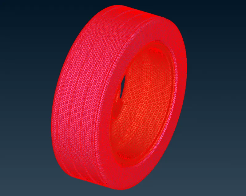
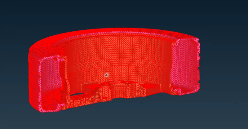
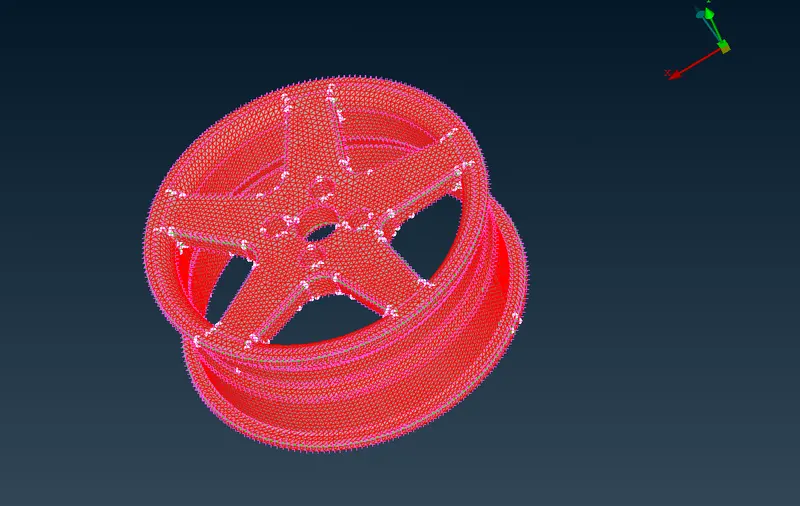
- Solve the quality criteria by using move tool in grids (mesh>classic mesh>grids>move)
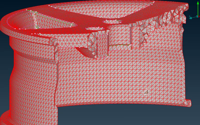
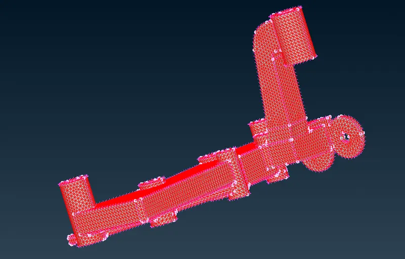
Midsurface Generation and Meshing
- Here some parts are below 5mm thickness so we can use casting method for midsurface mashing
- Casting is mainly used to obtain direct meshed model from the given model.
- It is an automatic mesh from the model.There is no need of midsurface genearation.
- Assign the quality criteria that is given and define the mesh perimeters.(F11-Quality criteria)
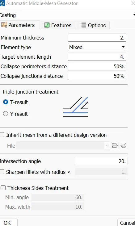
- Set the mesh parameters.
- For casting, go through the following steps Topo>Midsurface>Casting.
- After the casting, There are quality failures in the model.Fix the quality by using smooth,reconstruct,Fix quality tools in classic mesh.
- By using Move tool we can adjest the position of node of element and fix the quality issue.(classic mesh>grids>Move)
- Maintain the proper mesh surface by using the tool Align Manager.(Topo>Midsurface>Align Manager)
Connections For the Model
- Here we are dealing with different types connections that is mainly useful in simulation of mechanism.
- There are different types of connections used in ANSA such as Door hinches,rear windows,bolt connections etc.
- In the rear wheel assembly mainly used connections are spot weld connection, Bolt connection, RBE2 connection,CBUSH connection.
- Now we can start with RBE2 connection in Tyre and Rim area and Rim and Disc areas. First select elements-RBE2 in nastran deck. Select RBE2-many nodes by using loop option and enter.
- We can use RBE-2 connections in bolted areas also.(NAST>Element>RBE2>Many node)
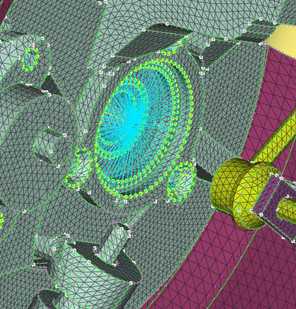
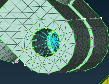
- From the above fig we get an cluster RBE2 connection.
- These two cluster RBE2 connections are connect with two Node RBE2 connections.(NAST>Element>RBE2>Two)
- In RBE2 connection center node is known as Master node and rest is slave nodes
- Create supperate files to store connections in model browser.
- For Spot welds, We have different method. At first create COG point using on COG tool. assign COG point as 3D point and convert 3D point to Spotweld point by using Convert>3D point>spotweld.
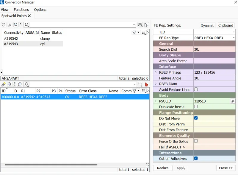
- Now select connection manager and select spotweld point. assign P1 and P2 for selecting PIDs. Assign FE rep type as RBE3-HEXA-RBE3. Assign RBE3 pinflags as 123456. select realize the spotweld deployed at the point.
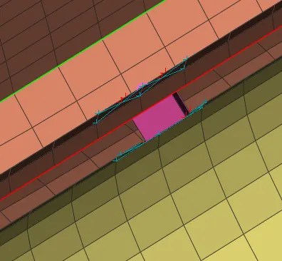
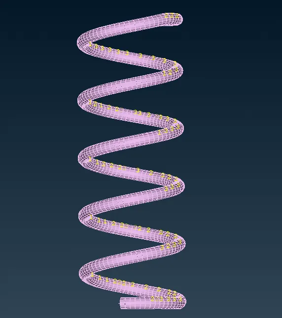
- we can represent spring like elments as CBAR connections.First create the midcurve for the spring and create the COG.(Topo>Points>On COG)
- Then go to nastran module and select CBAR and select the curve click enter then select COG after the middle click give element length and give PBAR property
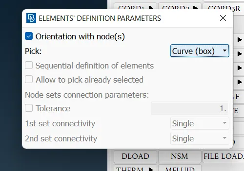
- After the connection we have to mirror the suspension mechnism by using Transform tool (Transform>copy>symmetry>mirror three point plane)
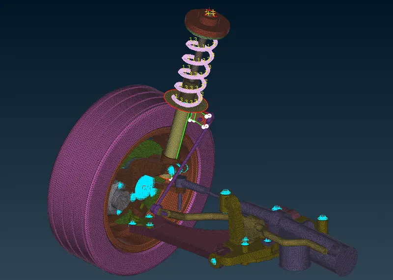
Before Transform
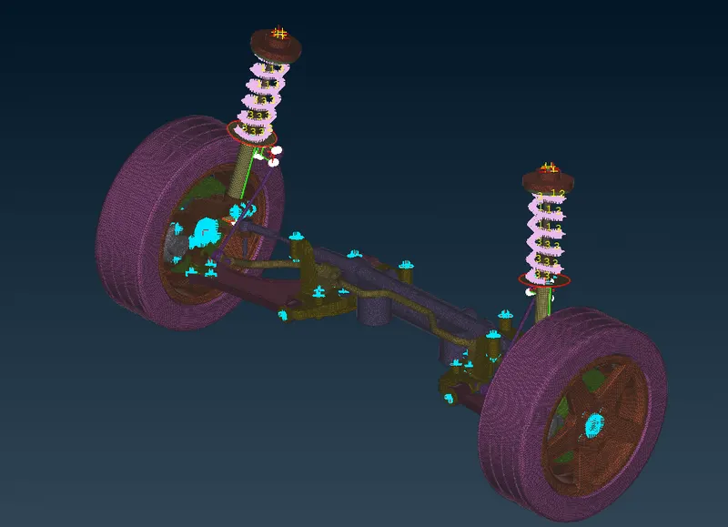
- After Transform
LEARNING OUTCOMES
- Learn how to do topological clean-up with no errors.
- Learn how to assigned separate PIDs for different surfaces and volumes.
- Aware of all the quality criterias and mesh parameters during mesh generation.Learned how to improve mesh flow and remove trias to achieve better mesh flow.
- Understood all the concepts regarding mid surface generation,volume mesh generation, meshing, connections used for NVH analysis in ANSA.
CONCLUSION
In this project, I have generated mid surfaces and volume mesh using different options available in ANSA. Able to achieve better mesh flow using smooth,reconstruct,swap,paste,move options. Eliminated kinks and raised edges. Successfully applied different quality criterias and mesh parameters for different parts and cleared off elements during mesh generation. Successfully deployed connections for the rear suspension.
Project 2 meshing on suspension assembly:
https://drive.google.com/file/d/1cMKGxnp1u1YZ9cFXXdduJvRB95hJ0qJw/view?usp=sharing