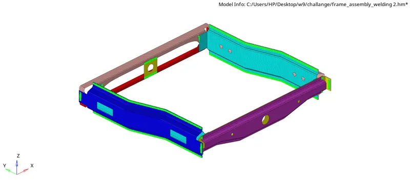
Week 9-Creation of 1D Connectors Challenge
AIM
Mesh the given geometry. Provided below are the quality parameters that you have to follow.
Target Element size - 5 Units
|
S.N |
Quality Criteria |
Value |
|
1 |
Aspect Ratio |
5 |
|
2 |
Skewness |
45 |
|
3 |
Warping |
15 |
|
4 |
Taper |
0.5 |
|
5 |
Min. Length |
2 Units |
|
6 |
Max. Length |
8 Units |
|
7 |
Min angle Quad |
45 |
|
8 |
Max angle Quad |
135 |
|
9 |
Min angle Tria |
30 |
|
10 |
Max angle Tria |
110 |
|
10 |
Tria % |
15 |
Create connector and Attach the various parts of the given model
1. Right_Rail_2 & Front_truss_1:- Seam-Quad(angled+capped+L)
2. Left_Rail_2 & Front_truss_1:- Quad elements
3. Front_truss_2, Front_truss_1 & Right_Rail_1:- Spot weld with 2 Layers and 5 mm Diameter
4. Front_truss_2, Front_truss_1 & Left_Rail_1:- Hexa (Adhesive)
5. Rear_truss_2 & Right_Rail_2:- Bolt Connector
6. Rear_truss_2 & Left_Rail_2:- Bolt Connector
7. Right_Rail_1 & Right_Rail_2:- Spot-weld with Rigid Elements
8. Left_Rail_1 & Left_Rail_2:- Spot-weld with Spring Elements
9. Rest all the component left Join them with suitable connectors
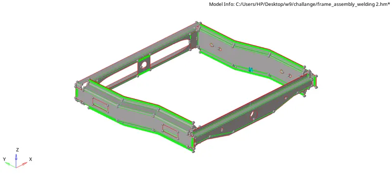
MODEL
PROCEDURE
- Open the hyperworks software.
- Open the hm file in hyper mesh software in optistruct profile
- The given model is an extracted midsurface so we have to mesh this model with proper mesh.
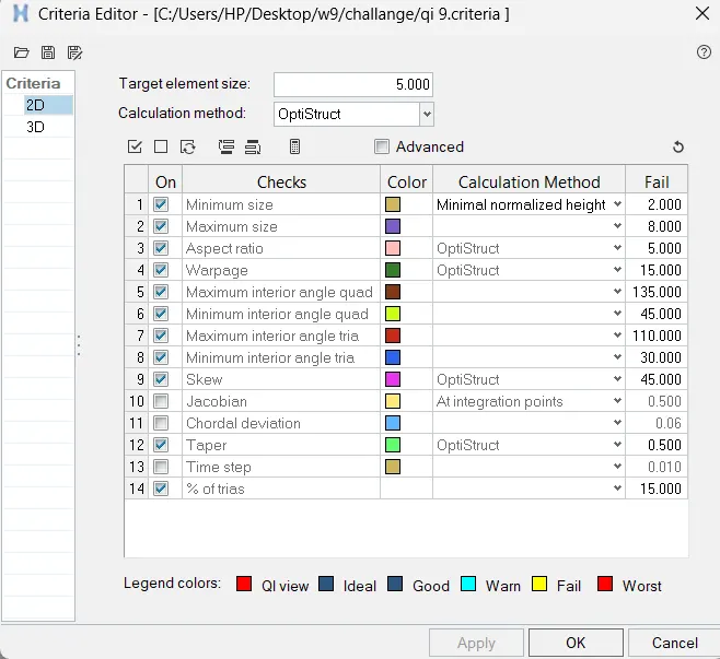
- Give the quality criteria and mesh parameters.(preference>criteria/mesh parameters)
- Go to 2D mesh menu and select automesh option, change the element size to 5, element type to mixed and select the mid surface and click mesh to generate the mesh.(2D>automesh>select surface>mesh)
- After generating the mesh, check for the quality criteria, to perform the quality criteria.(2D>quality index)
- Use element cleanup for fixing the off elements.(2D>elementclean up)
- Next step is to give connection as per given.
Right_Rail_2 & Front_truss_1:- Seam-Quad(angled+capped+L)
- Go to the connectors panel in 2D/3D.(2D>connectors>seam)
- Now select the nodes where the weld has to be created by clicking nodes list.
- Specify spacing as target length and select the components which are to be connected.
- Specify the tolerance depends on distance between the components.
- Select the type as Seam-Quad(angled+capped+L)
- Hit on create to create seam weld

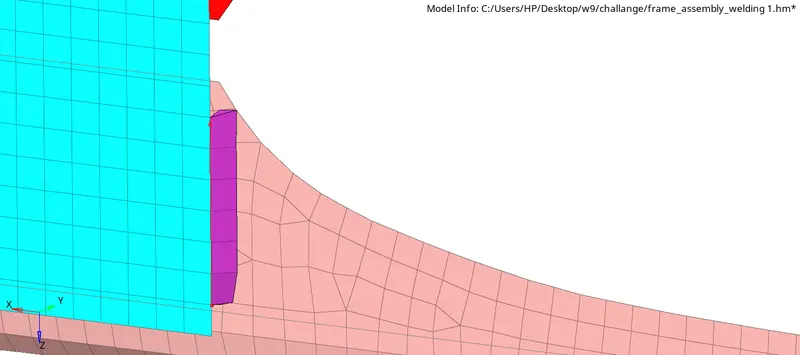
- After the creation of weld shown below.
Left_Rail_2 & Front_truss_1:- Quad elements
- Go to the connectors panel in 2D/3D.(2D>connectors>seam)
- Now select the nodes where the weld has to be created by clicking nodes list.
- Specify spacing as target length and select the components which are to be connected.
- Specify the tolerance depends on distance between the components.
- Select the type as Quad elements
- Hit on create to create seam weld

- After the creation of weld shown below.
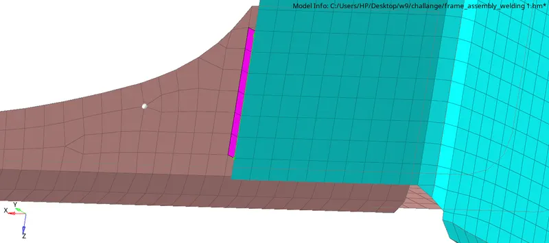
Front_truss_2, Front_truss_1 & Right_Rail_1:- Spot weld with 2 Layers and 5 mm Diameter
- Go to the connectors panel in 2D/3D.(2D>connectors>spot)
- Now select the nodes where the weld has to be created by clicking nodes list.
- Specify diameter and select the components which are to be connected.
- Specify the tolerance depends on distance between the components.
- Select the type as weld
- Hit on create to create seam weld

- After the creation of weld shown below.
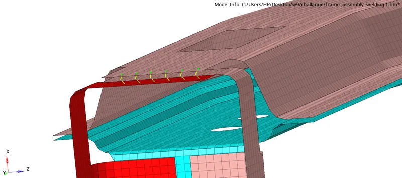
Front_truss_2, Front_truss_1 & Left_Rail_1:- Hexa (Adhesive)
- Go to the connectors panel in 2D/3D.(2D>connectors>seam)
- Now select the nodes where the weld has to be created by clicking nodes list.
- Specify spacing as target length and select the components which are to be connected.
- Specify the tolerance depends on distance between the components.
- Add the width of element.
- Select the type as Hexa (Adhesive)

- After the creation of weld shown below.
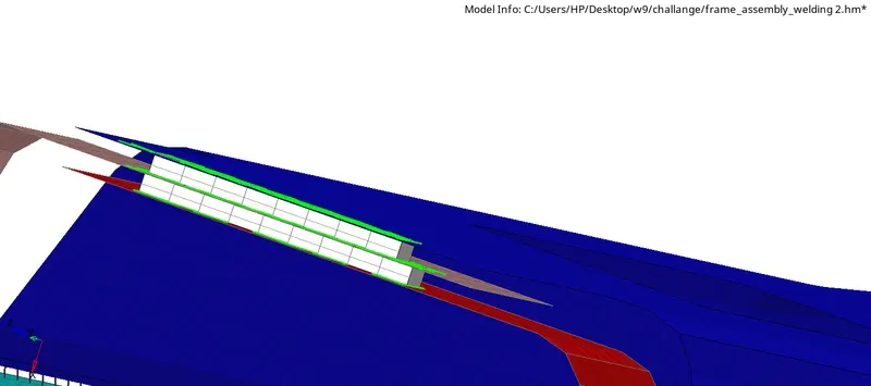
Rear_truss_2 & Right_Rail_2:- Bolt Connector
- Go to the connectors panel in 2D/3D.(2D>connectors>seam)
- Now select the nodes where the weld has to be created by clicking nodes list.
- Select the components which are to be connected.
- Specify the tolerance depends on distance between the components.
- Select the type as Bolt(general).

- After the creation of weld shown below.
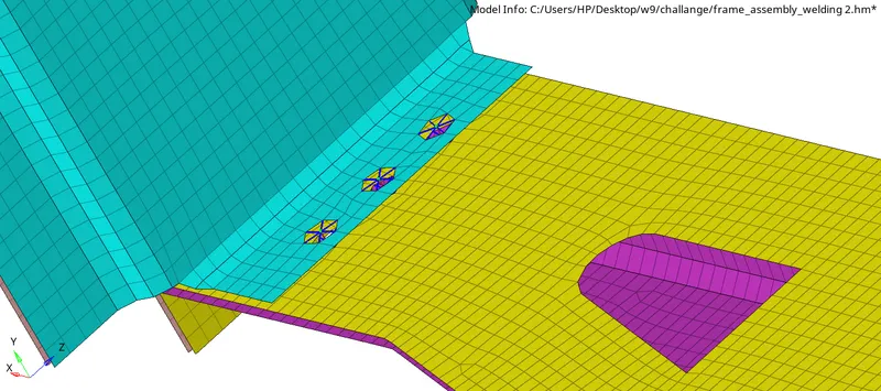
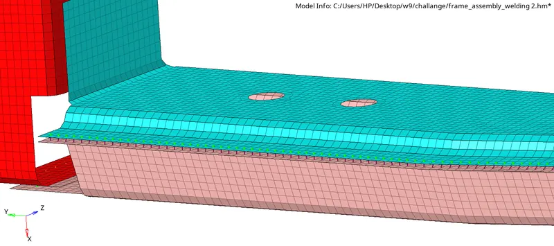
Right_Rail_1 & Right_Rail_2:- Spot-weld with Rigid Elements
- Go through same procedure that is explained in spot weld section
- Change the type to Rigid

- After the creation of weld shown below
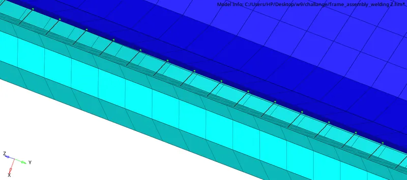
Left_Rail_1 & Left_Rail_2:- Spot-weld with Spring Elements
- Go through same procedure that is explained in spot weld section
- Change the type to Spring

- After the creation of weld shown below
CONCLUSION
The meshing and connnection has been successfully completed in the given model.