Wiring harness routing & packaging Rules Week 3 Challenge
Clip Definition
This is another important component of the Wiring harness which should be defined before wiring harness routing. Following important parameters required to be defined
Entry Point&Plane
Base Plane
Exit plane
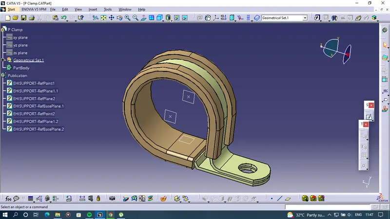
- Created an Entry point and plane at the centre of the P clamp side.
- Accordingly, created an Exit point and plane at the centre of another side of the P clamp.
- Then Created a Base pane at 2 mm offset from the base of the P clamp.
- Selected a command called "Electrical Support Part" which defined the Name of the part, in the First plane definition the Entry point and plane are defined, in the second plane definition exit point and the plane is defined as the clamp that can be used in both ways and has two entry and exit points.
- In the Base plane definition base plane earlier created is defined.
Backshell Definition
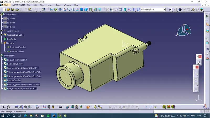
- Backshells are plastic molded parts used at the wire entry side of connectors either for protection or to improve the aesthetics/appearance of the harness.
- These are not mandatory parts of the Wiring harness. Are always optional and driven by Cost.
- Methodology and logic to define the Point&Axis system are the same as Connector
Connection system.
- Ensure that the defined axis&Orientation should be identical to the mating part.
- Created an Axis system at the connector meeting point and created a point at the Bundle Entry.
- Then the body is defined as a Backshell by the backshell definition command in which extra length is selected as unset.
- Then the Backshell connection point command is selected this command is similar to the connector connection point and the definition is also similar.
Corrugated Tubes
- Corrugated tubes, Convolutes, Sleeves and many other types of coverings are used to protect the wiring harness.
- Graphical representations of coverings are applied on bundles.
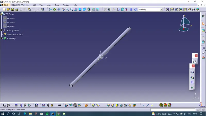
- To create a Corrugated tube let's take an example of a 5mm tube
- Selected Protection Covering the part select part body Define the Inner Diameter, Thickness, and the Bend Radius in this case Inner diameter is 3mm and thickness is 1mm and for bend radius, it is 1.5 times the total diameter of the corrugated tube.
|
Name |
ID (mm) |
OD (mm) |
Thickness (mm) |
|
15mm COT |
12 |
15 |
1.5 |
|
20mm COT |
17 |
20 |
1.5 |
|
35mm COT |
32 |
35 |
1.5 |
|
10mm COT |
7 |
10 |
1.5 |
|
5mm COT |
3 |
5 |
1 |
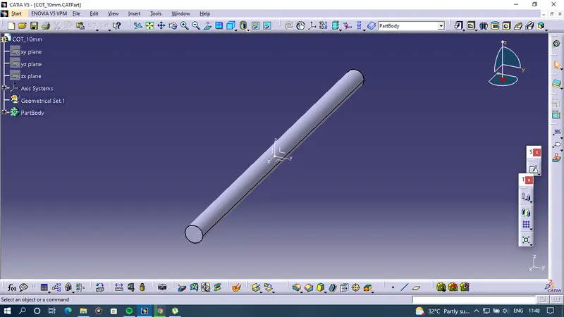
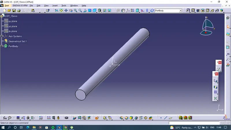
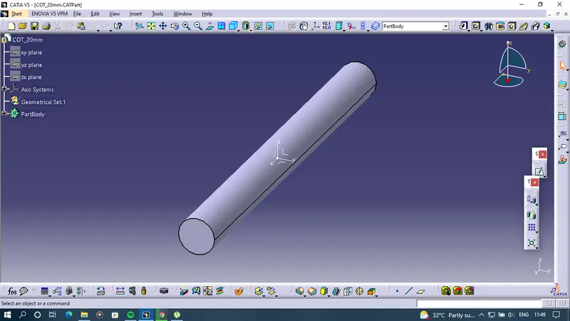
Accordingly, tubes were created as per the above-mentioned table
COT 5mm
COT 10mm
COT 15mm
COT 20mm
COT 35mm
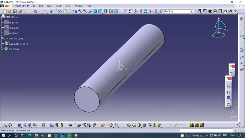
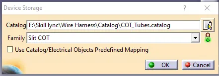
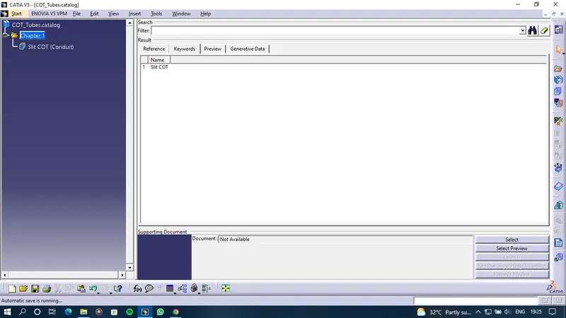
SLIT COT Family