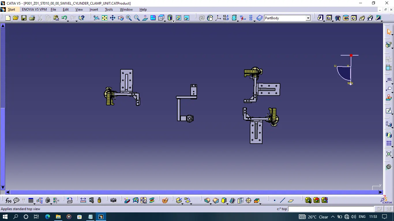
Week 6:- Clamp Unit & Pin-Clamp Unit Design Challenge
SWIVEL CYLINDER CLAMP UNIT
Project Named as P001_Z01_ST010_00_00
whereas,
P = Project no.
Z = Zone no.
ST = Station no.
It is necessary to have two pins to lock the car panel (component). And here one pin must arrest 4 ways (4 translations) and the other must arrest 2 ways (ie rotational ) of the car panel.
In this case components, 3 Swivel Cylinder clamp units and 1 Pin Clamp unit are used.
Some standards dimensions
The pin should engage 3mm to 5mm from the component entry surface.
The distance Between the Pin flange and the bottom of the component must be 10mm to 15mm.
There must be keep space for spacers of 5mm
The spacers dimensions - 1 spacer of 2mm, 2 spacers of 1mm and 2 spacers of 0.5mm.
The procedure followed for SWIVEL CYLINDER CLAMP UNIT
-Parts of this unit are the Clamp arm, Clamp Myler, Rest Myler, Standard swivel cylinder, Blade, Pin, Riser with a rib, Male and female stoppers, Bushes and Spacers.
- To create a swivel cylinder unit firstly set a specific position where the clamp unit a perfectly suited.
- At first created an L shaped clamp arm having a thickness of 19mm, length of 260mm and breadth of 100mm also created a supporting block for a pin having a length of 70mm breadth of 30mm and thickness of 8mm on both sides of the clamp arm.
- Also, a hole is created in the clamp arm of diameter 18mm for the bush which will piston of the cylinder.
-Then created a blade for the cylinder unit having a short profile and created 2 holes in the blade for mounting bushes 1 for clamp arm support bush and the other for cylinder support.
- Accordingly, created 3 bushes have an inner dia of 12 mm and another dia of 18mm with a length of 19mm.
- The hole on the blade for clamp arm mounting is positioned in such a way that the stroke of the piston should be 100mm.
- Positions of bushes are one for the clamp arm support block, one for the clamp arm and the remaining one for cylinder support on the blade.
- Imported a standard swivel cylinder in this case it is CKG_1B_63_100Y.
- Then the cylinder is mounted on a fixed location where the bushes are provided one on the clamp arm and the other on the blade and clamp armhole for the piston of the cylinder.
-Now created a pin of dia 12mm for clamp arm and blade mounting with a head of hexagonal shape having circular dia as 16mm and having a thickness of 6mm.
- Now, created a riser for cylinder unit with L shaped having dimensions 600X200X20mm and also created a rib of 280X140X20 mm.
-After that male and female stoppers are created according to the clamp arm and blade.
- As the shape of the clamp arm has L shaped two sets of the clamp and the rest mylers are used.
- Then Created a set of L shaped clamp mylar with dimensions length of 50mm and a width of 20mm.
- The height of the clamp Myler depends on the position of the clamp as per the surface where we are going to mount that clamp mylar.
- Dimensions of the rest mylar are also length of 50 mm and width of 20mm having an L shape as mentioned above rest mylar height also depends on the position and surface where the rest mylar is mounted.
- A chamfer of 8mm length and 45 degrees of angle is given to both rest and clamp mylers.
- As per the general procedure there will be always a tolerance in every part of the unit to overcome this tolerance shims/spacers are used.
-The dimensions of spacers are standard and are mentioned above.
-As per the holes on the clamp arm the holes are created on rest and clamp mylars with 8mm dia and 30 mm apart from each other.
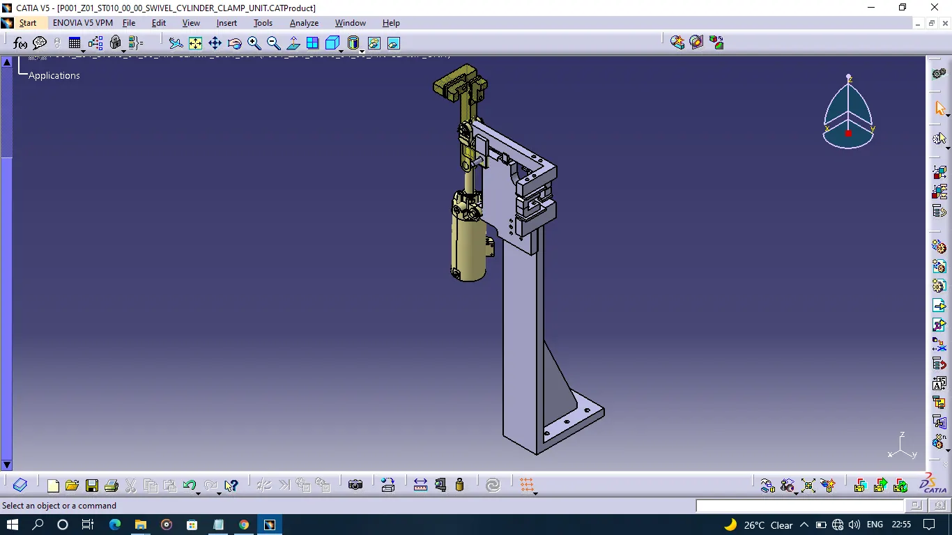
- A open position is shown of the clamp arm in yellow colour having some transparency.
The procedure followed for PIN-CLAMP UNIT
- Created a Pin of specific dimensions wrt the component, in this case, it is a pin of dia 45mm.
- The axis of the pin and the component hole should be coincident with each other.
- Following through that created a pin retainer wrt to pin earlier created.
- After creating a pin retainer there must be a hole in the retainer for the pin for making an attachment to the pin.
- To tighten the pin and retainer used a bolt from dictionaries of M12 standards.
- Created 2 blocks one having dimensions of 170X62X20mm and the other 180X62X20mm respectively.
- For the Pin-clamp unit we used a riser of clamp unit as a riser for the pin-clamp unit.
- The dowel holes created were 8 mm in diameter and 40mm apart from each other also a screw hole was 9 mm in dimension on both blocks, pin retainer and riser.
-The dimensions of spacers are standard and are mentioned above.
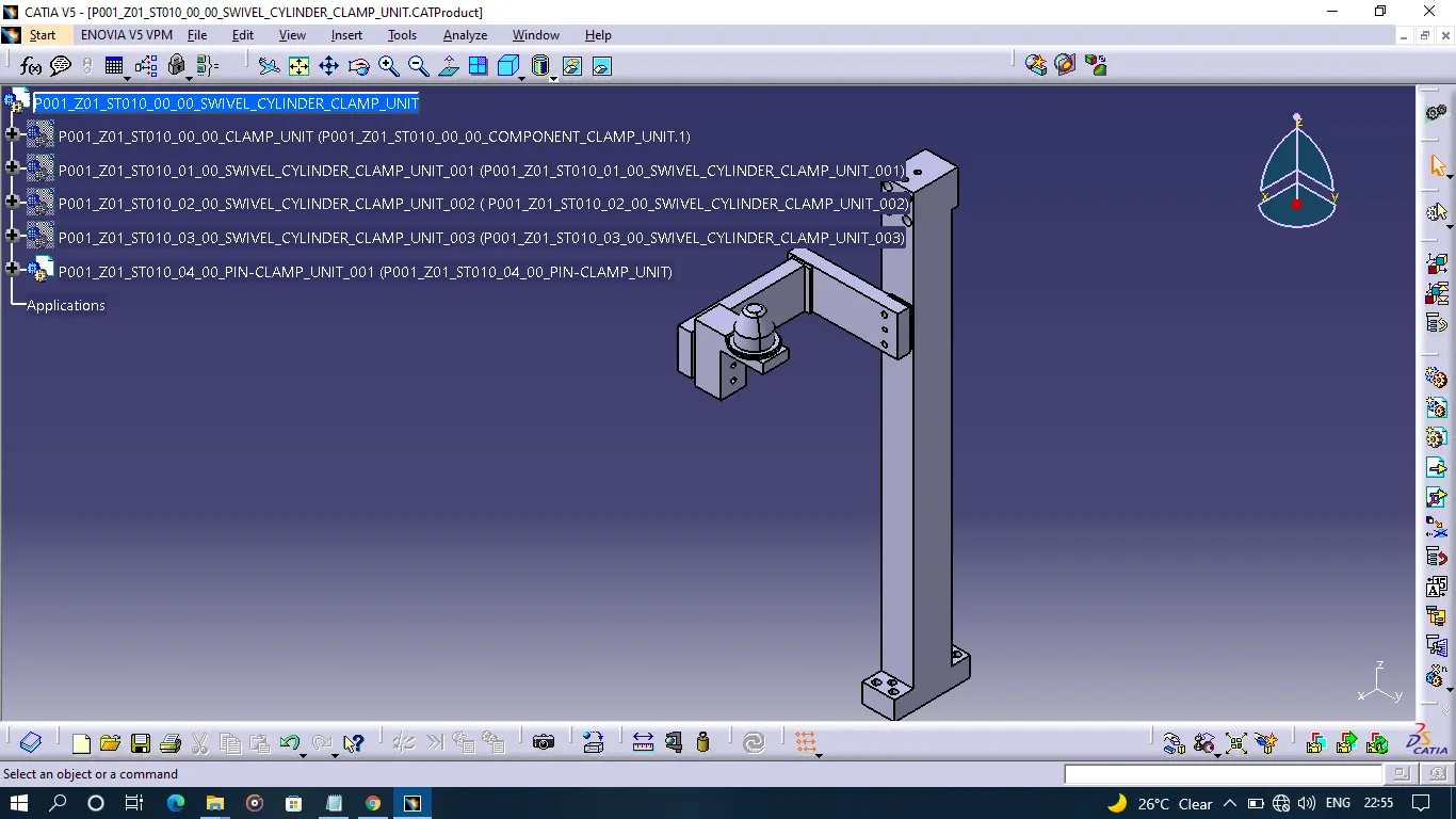
Pin-clamp_unit
Swivel_Cylinder_unit
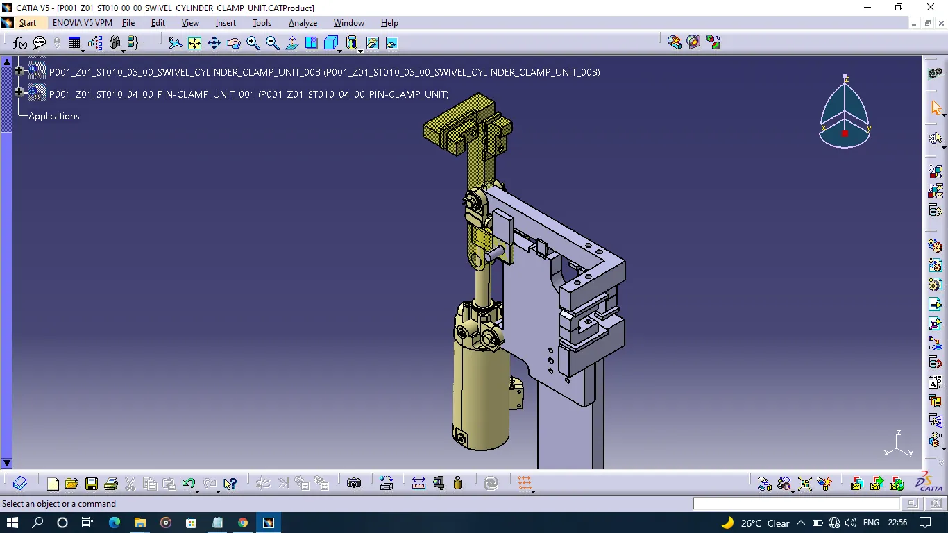
Swivel_Cylinder_unit_closed_look
Top_view_with_component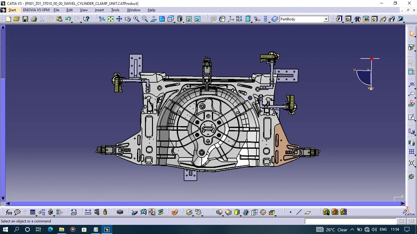
Figure_without_component_top_view