Week 8:- 3D Finishing - Challenges 1
Que 1st Ans:-
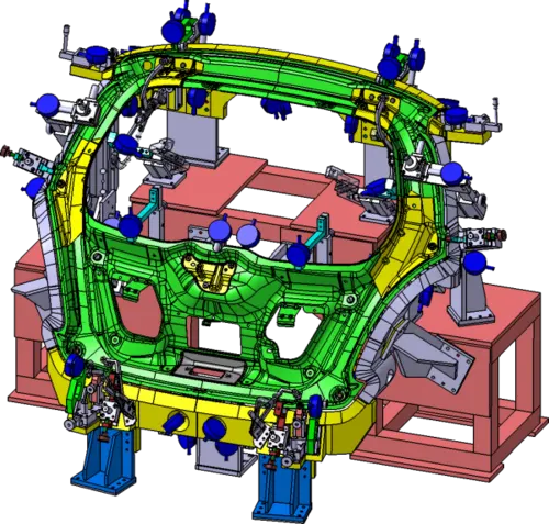
The 3D finish is the process where the design is being finished and to be ready for final simulation and 2D detailing.
- While finishing the design the nominality of holes is checked which ensures the easy assembly of all the units.
- The Holes concentricity and holes sizes are checked which ensures the easy assemblies of different parts.
-Fasteners are implemented as per the hole sizes and the standard colour codes as per the customer's requirement are applied to differentiate the type of hole whether it's a simple hole threaded hole or a counterbore hole.
-Renaming of the assembly and the part is done for the simulation and 2D detailing.
Que 2nd Ans:-
1] Hole Conectericity and hole sizes - All part Hole concentricity should be checked while finishing the parts.
2] Machining Area - Thw machining area is every part should be defined and the machining area should be of standard colour code.
3] Mylar splitting as per panel profile - Mylar splitting should be confirmed while finishing the design.
4] Gaps checking - Gaps should be maintained between units to avoid a clash between the different units.
5] Holes colouring - Color code as per the customer requirement should be applied in the 3D finishing.
6] Nominality - All unit dimensions should be maintained nominal to facilitate easy assembly of the unit
Que 3rd Ans:-
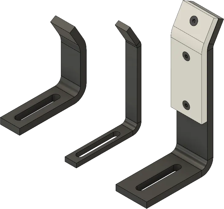
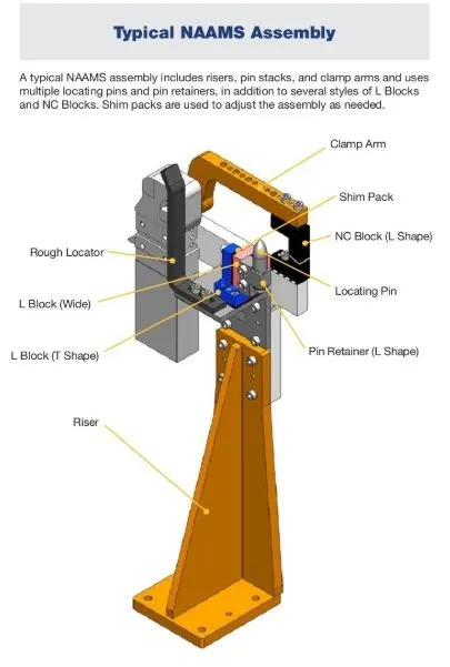
- Rough locators are used to helping locate workpieces in the automation process.
- Locating refers to the desired location where you want the piece to be and why it is getting worked on either by a person, team or robot.
- Rough locator is a part designed to guide the operator to locate the car panel onto the pins according.
- A rough locator can be a standard or a make part.
- The accuracy and consistency increase due to the use of rough locators.
- Rough locators are set according to the angle of the respective panel hence part can only be loaded in a defined direction and orientation.
Que 4th Ans:-
1] Rough locators should guide the panel in a pin arresting direction.
2] Rough locators should be placed at the edge of the car panel, which has to guide.
3] Rough locators should shart guiding the panel from 10mm to 15mm to the start of the pin engagement.
4] Rough locators should be designed with two slots to mount the easy adjustments.
5] The Rough locators have to be placed at the same angle as the car part edge with a minimum distance of 2-5mm from the edge of the car panel.
6] Rough locators should be in the direction of car part guiding.
Que 5th Ans:-
- Car Body in White (BIW) is a complicated steel structure including 200 - 500 sheets with complex shapes and are assembled.
-Welding is used in Automobile industries and requirements for fixtures that ease the welding process is a continuous development task in any industry.
- It includes the study of the matrix and weld point position there are two types of weld points Geo weld points and second is Re spot welds.
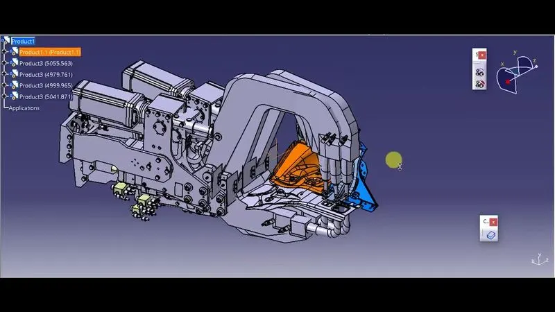
- It includes the study of the weld gun which is used for the welding process.
- The fixture designed for the car panel is to hole it on the position the weld gun position is checked over the predefined spot weld points.
- The weld spots have defined the axis of the weld spot along with them along the welding direction mist be normal to the surface.
Que 6th Ans:-
Welding is a very complicated and time-consuming process therefore we need to consider while during the gun study
1] The number of weld spots for the panel the time required to spot each the total time required to complete all the weld spots.
2] The Axis of the weld sport along the welding direction must be normal to the weld surface.
3] The Robot cycle must be considered while gun study because based on the distance of each tag point from home position motion type speed and acceleration one can obtain cycle time for each device assigned with sequence.
Que 7th Ans:-
The pneumatic system should be efficient and leak-free. Sometimes they are not because of improper tube line trouting.
Que 8th Ans:-
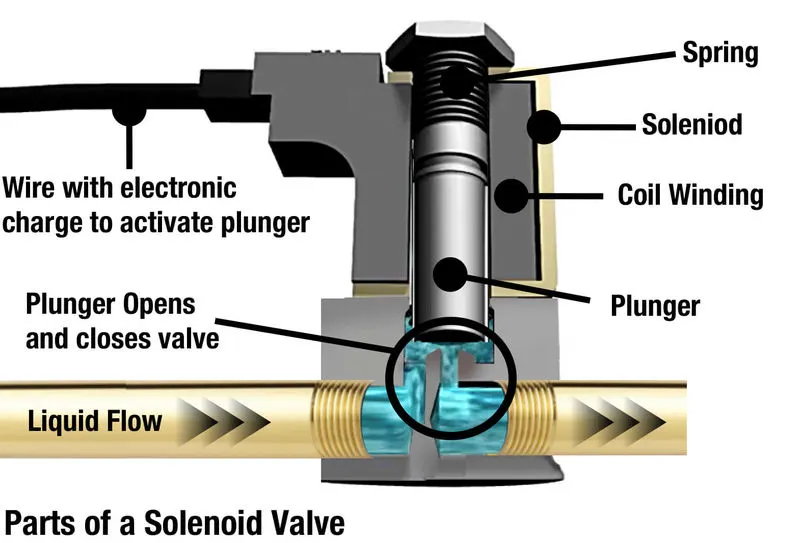
It is a vale that is operated electromechanically. Solenoid valves differ in the characteristics of the electric current they use and the strength of the magnetic field they generate.
- Solenoid valves are the most frequently used control element in fluidics.
- Their tasks are to shut off release dose distributed or mix fluids.
- Solenoids offer fast and safe switching high-reliability long service life good medium compatibility of the material used low control power and compact design.
The Parts of the solenoid valve are as follows:-
1] Valve Body - The valve is usually connected to the process flow pipeline to control the flow of certain fluid or air.
2] Coil/ Solenoid - Body if the solenoid coil is cylindrical and it is hollow from the inside. The body is covered with steel covering inside it there is a solenoid coil.
3] Inlet port - This is the part from where a certain fluid enters the valve for further processing.
4] Outlet port - The fluid which needs to be flow is flow through the outlet valve the solenoid controls the flow of the outlet port.
5] Coil Winding - It consists of several turns of a magnetic material like steel or iron, The coil shape is similar to a hollow cylinder. Because of this coil plunger or piston moves in the vertical direction.
6] Plunger or piston - It is a solid metal part that is placed inside the solenoid vale inner portion when the electric current passes through the solenoid valve the magnetic field generated in the solenoid coil which moves the plunger vertically after the current is shut off the plunger remains it is stated position due to the force of spring.
7] Spring - The plunger moves in due to the magnetic field against the action of the spring, this action against the magnetic field tends the plunger to remain in the actuated position.
Que 9th Ans:-
Valve Blank
- On the solenoid bank each of the solenoid vales perfectly controls the feed of the high-pressure servo air to a single pneumatic valve.
- Valve vank is the arrrangement of no. of soliend vales.
- Valve bank will have a common inlet port a single line to each of the pneumatic valves and independent vent passages to each solenoid.
- the valve is actuated by selectively energising the corresponding solid to allow servo air to the servo air to the servo air to the servo part of the valve. To return the valve to its fail-safe position the solenoid is de-energized to vent the servo port of the valve to the ambient.
- Two-stage solenoids are designed to provide fast response times. The electrical configuration is a dual coil redundant design providing an isolated circuit topology housed in a single package each coil is independent and identical in function:-
common features of valve bank -
1] These are designed for high viberation levels.
2] These are Designed for high-temperature environments.
3] It uses a minimum alloy manifold for lightweight.
4] Design architecture allows easy selection of two to six solenoid valves.
Que 10th Ans:-
- A unit designed to sense car panels using electrical sensors is called a sensor unit.
- Sensor is a device that detects or measures a physical property and records, indicates or otherwise responds to it.
The sensor is sent to the PLC so the next process is executed by the signal.
Sensors in Industrial Automations
- In the industrial automation section sensors play a very important role to make the products intelligent and highly automatic. These allow one to detect analyze measure and process various changes like change in position length height appearance and displacement that occurs in the production sites.
- These sensors also play an important role in predicting and preventing many future events thus catering to the needs of many sensing applications.
- The following are the various types of sensors used in industrial automation proximity sensors vision sensors ultrasonic sensors position sensors photoelectric sensors temperature sensors inclination sensors.
- Displacement sensors are used in the provision positioning of the objection at the nanometer level and the measurement of precession thickness of disk drives assembly line testing and machine tool meteorology, it is widely used in machining.
- Autopilot System in Aircrafts
Que 11th Ans:-
Sensors are used for measuring physical properties like temperature, Resistance, Capacitance, Conduction, Heat Transfer etc.
Following are the type of Sensors used in Automation
- Temperature sensor.
- Proximity sensor.
- Accelerator.
- IR Sensor (Infrared sensor )
- Pressure sensor
- Flow And level sensor
- Humidity sensor
- Smoke, gas and Alcohol sensor
- Touch Sensor.
- Color Sensor.
- Tilt Sensor.