Fender Design Challenge
Project Title: FENDER DESIGN
Objective: The main object of this project is to design the front fender's BIW(Body in white) using the fender skin data and the master section as the data by using NX CAD.
Introduction :
Fender is the American English term for the part of an automobile, motorcycle or other vehicle body that frames a wheel nicely. Its primary purpose is to prevent sand, rocks, mud, liquids, and other roads spray from being thrown into the air by the rotating tire. The fender is typically rigid and can be damaged by contact with the road surface.
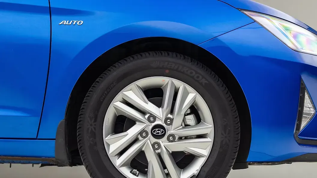
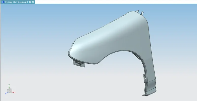
Sticky materials, such as mud, may adhere to the smooth outer tire surface, while smooth loose objects, such as stones, can become temporarily embedded in the tread grooves as the tire rolls over the ground. These materials can be ejected from the tire's surface at high velocity as the tire imparts kinetic energy to the attached objects. For a vehicle moving forward, the top of the trie is rotating upward and forward and can throw objects into the air at other vehicles or pedestrians in front of the vehicle. The fender is a front outer side member of a car, which covers the wheel side. It has so many small features with ups and downs.
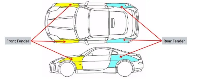
The Importance of car Fenders :
- The fenders are an intricate sheet of metal covering the wheel well of your car.
- Fenders are designed to provide resistance against wind and other roadside debris.
- When you travel on rough terrains your vehicle might get minor scratches and dents which look no better. Frequent road bumps can cause your car's paint to chip off which needs a paint job done.
- The car fenders are on either side of the front and rear wheels. The front car fenders begin where the front door hinges run and end just before the bumper. The rear car fenders start where the back doors close and terminate before the back bumpers.
Types of Fenders :
There are two types of fenders.
- Full Bumper Type
- Half Bumper Type
Full Bumper Type :
This type of bumper is not commonly used because this design is more scrap-producing during manufacturing. The blank of steel or aluminium used to produce this type has more wastage. This type is not economically good to manufacture.
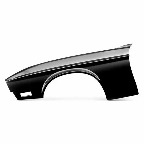
Half Bumper type :
These types of fenders are most commonly used. The cons of full bumper type are satisfied in this design, and the blank area of wastage while producing the part is drastically reduced by scrap management.
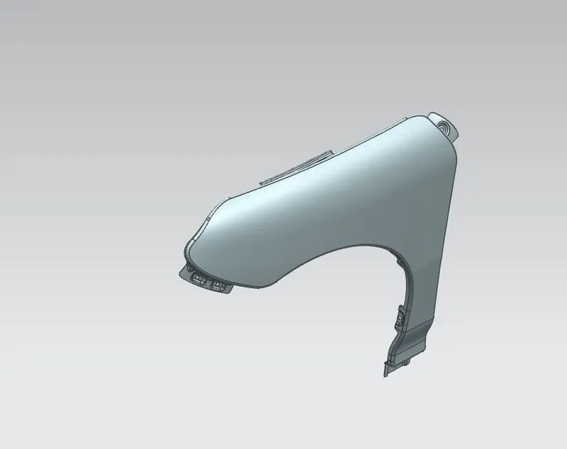
Purposes of Fender :
Cleanliness: Protect the car, occupants and passers-by from items, water, mud, snow, and ice, thrown off the tires as you drive.
Safety: Protects pedestrians from the wheel, e.g. it's better to be it by a laterally moving fender than a rolling tire, keeps loose, streaming items from being wrapped up in a rolling wheel.
Aerodynamics: Smooths the car profile so you don't get a lot of drag off the uncovered wheels. Some fenders are enclosed on the side for this.
General Appearance: Looks better with fender, gives a finished look and looks more streamlined.
Front Fender Desing :
In the given master section to create the drip area and for the still mount, the Bumper mount and the A-pillar mount create your design according to the engineering standard.
- Drip Area
- Sill Mount
- Bumper Mount
- A-Pillar Mount
- Splash/Baffle Mount
Design of Drip Mount Area :
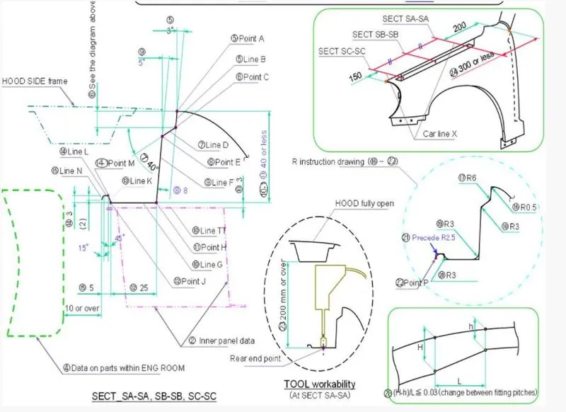
Master Section To Fellow and Create Drip Design :
Skin Data :
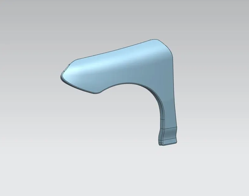
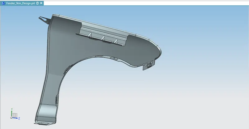
It is a most important mounting unit of a fender. It's connected with the engine compartment and therefore a lot of design constraints are to be followed while designing the drip area. It should have sufficient clearance from the front and rear end of the fender to accommodate the cowl mounting region and the headlamp housing unit respectively.
From the master section, we have optimised value for draft, drawing and assembly points of view. Such as the distance from the engine compartment is 10mm, the height of the fender etc.
Design Criteria :
- Embosses are provided to increase strength.
- Smooth curves are designed for easy manufacturing of panels.
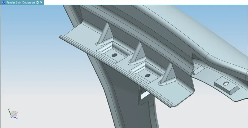
- Ribs are provided to the drip area mount to give structural support and extra strength.
- Maintain an extra 10mm from the flat surface for the fastener holes.
- All fillets should maintain a 1.5 or 3mm radius in most regions.
- The thickness of the fender is 0.75mm.
DESIGN OF DRIP :
- The curve selection command is used for creating curves on the surface of the flange to trim the extra sheet metal.
- The position is 200 mm from the cowl and 150 mm from the headlight position.
- The flange should be about 7 degrees, then 40 degrees down and 5 degrees down which should be the total length of 40 mm or less from the top of the fender.
- Then the flat length of 25 mm is given.
- The last projection is followed as per dimensions using the Pythagoras theorem.
- Then the flange holes were created for mounting points.
A-PILLAR MOUNT DESIGN
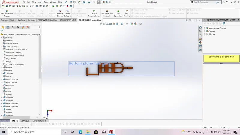
- The consideration is taken from the place at cowl is placed.
- It is taken at the back of the drip mount.
- The A-pillar mounting is created considering a sliding type.
BUMPER MOUNTING :
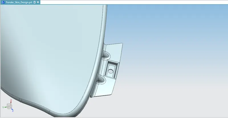
- The bumper mounting is placed headlights of headlight position.
- This also has a flange with holes for mountings
SILL MOUNTINGS :
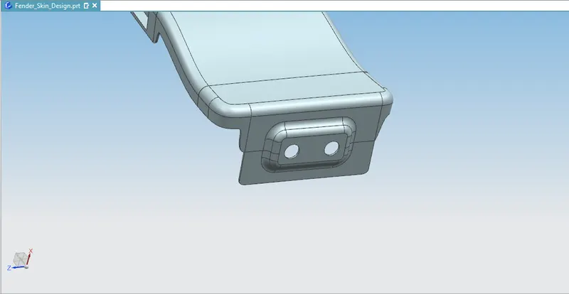
- The sill mounting is done by extension of the sill area flange
- After the extension of the flange, holes were made for mountings.
- Embosses were created for the hole mounting points that provide more strength.
WHEEL ARCH MOUNTINGS :
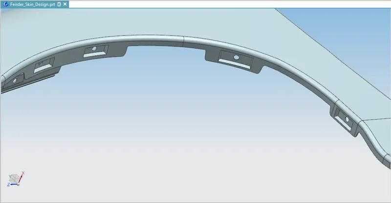
- The wheel arch design always depends on regulations based in different countries like European, Japan, the US etc.
- The flange provided for the wheel arch is provided with just holes for push pin clips to mount the wheel arch.
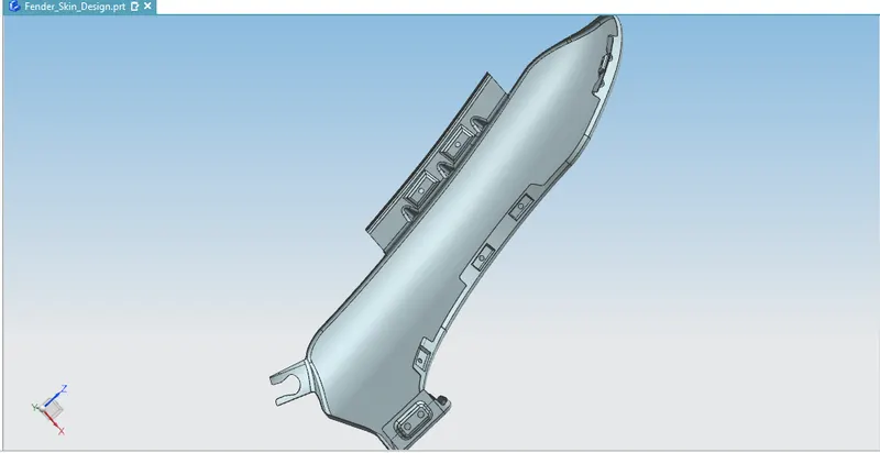
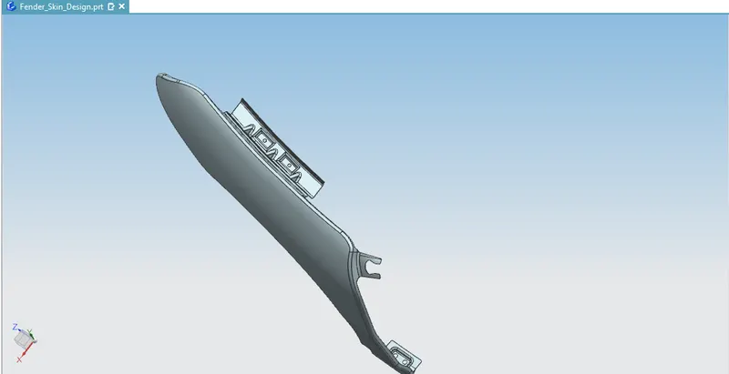
DIFFERENT VIEWS OF FENDER :