Wiring harness design in CATIA V5 - 3D modeling Week 7 Challenge
The assumptions were made for harness bundle diameters are:-
Main branch = 10mm diameter
Sub-branches = 05mm diameter
To create the following harness firstly created a product assembly file named" Assembly_Wiring_Harness_Context" and also created sub product file as "Assembly_Geometrical_Bundle" in which the wiring harness routing is done.
- Firstly Imported all required connectors in the harness assembly and made sure that all the components should be electrically defined. Following are the connectors used in this harness assembly:-
- DT06-4S (2x)
- DT06-6S
- DT06-2S (2x)
- DT06-08SA
- Then Use the Multi Brancheable document to join two connectors.
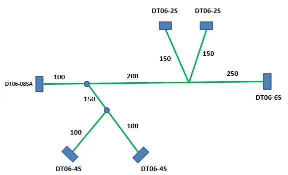
- Created the Main branch connecting the DT06-6S and DT06-08SA connectors.
- Maintained the distance as mentioned in the figure below. Similarly connected the other connectors as mentioned by the Bundle Segment command and used Add Branch point command to create the bundle segments in the following image.
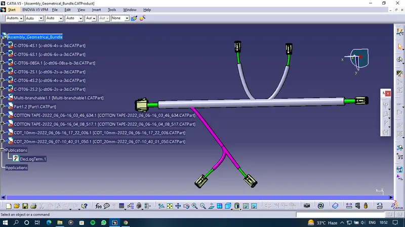
Then added the Protective covering on all branches and Kept the end extremity at 30mm (from the end of the connector)
-Created a product file and navigate to the Electrical Harness Flattening for wire harness flattening option and
save it in the same location where the wire harness or routing assembly is stored.
-Define the harness flattening parameters in order to flatten the required wire harness assembly.
-While defining the harness flattening parameters in the drawing menu single line is selected for the bundle
segment and the double line are selected for protective coverings in order to differentiate between the wire bundle and cot tubes in drafting.
- Select the extract option from the Electrical Harness flattening workbench and select the Geometric bundle
product in the wire harness assembly product file.
-Then wire harness assembly is imported to the Wire flattening product file with EHF extension added to the
geometric bundle assembly name.
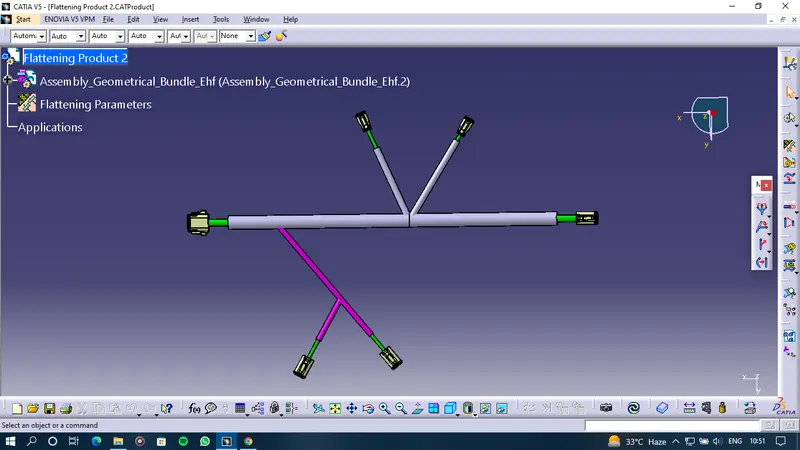
- Select the flatten option to flatten the wire harness assembly.
- Then select the active plane, then select any one branch and then select the select all branches'.
-If there is no discontinuity in the bundle segment then all the branches will be selected and by pressing ok the wire harness assembly will be flattened.
FOR DRAFTING
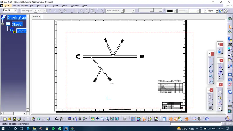
- Created a new drawing file and save the file in the same location.
- Inserted the title block template
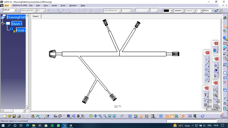
- Add the front view of the harness assembly by selecting any one of the flat faces of the connector and orient
the view as per the requirement.
- Go to the properties of the view and select the'3D Wireframe on is always a visible option in order to see
properly the Wire bundle, connectors and the protective coverings.
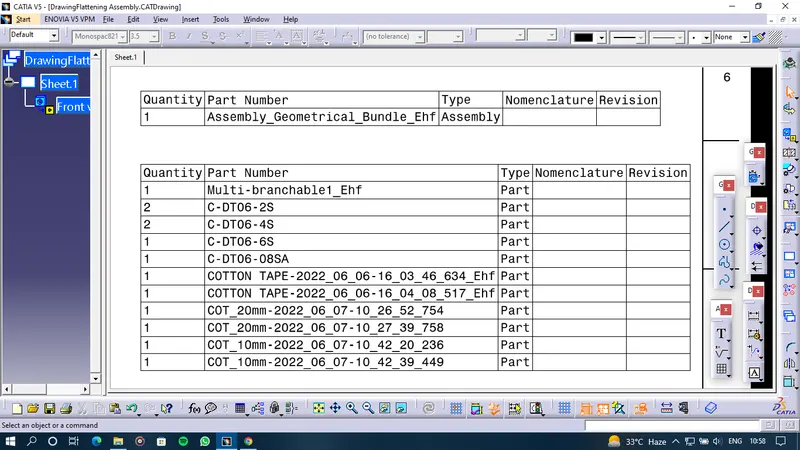
BILL OF MATERIAL