Wiring harness design in CATIA V5 - 3D modeling Week 5 & 6 Challenge
Wire Harness Assembly:-
In Wie harness Assembly time there are some sub-assembly
The first step is to download the CAD file of required parts like Connector, Backshell, corrugated tubes, clips etc.
Then it is important to define all the components electrically here in our project we have to define connectors
electrically
For connector, we define connecter connection point&bundle entry point.
To define the connector connection point, we need an axis for the coincidence axis and Orientation axis.
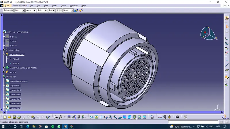
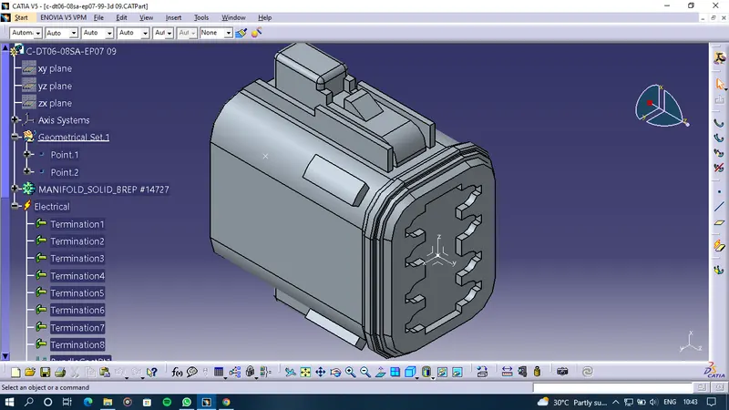
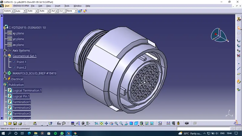
These are the connector defined electrically with the Connector connection point and bundle entry point
Connector 1 Connector 2
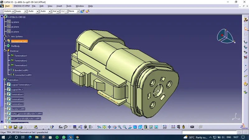
Connector 3 Connector 4
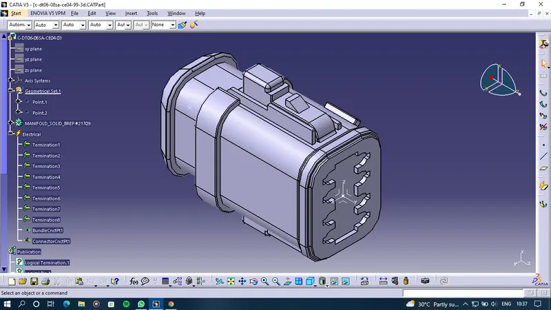
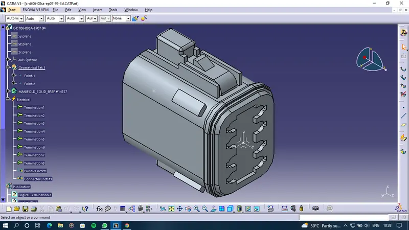
Connector 5 Connector 6
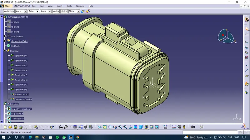
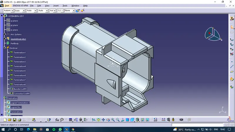
Connector 7 Connector 8
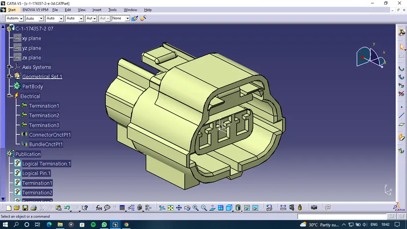
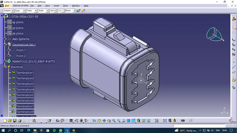
Connector 9 Connector 10
- Firstly all connectors(1,2,3,4,5) are imported into the assembly designed and named the assembly B
- Before routing it is very important to add all the components in the geometrical bundle then we can route otherwise route will not happen.
- Then Use the Multi Brancheable document to join two connectors(1 and 5)
- Then Connected other connectors using the bundle segment command in the given manner
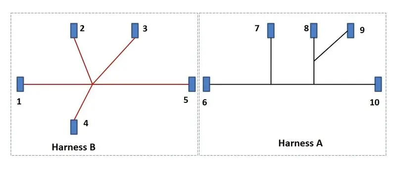
- A similar process is done for Harness A with 6,7,8,9,10 connectors
- Both the assemblies are saved separately and then imported into the Harness A+ Harness B product file.
- Then both the assemblies are connected by connecting the 5 and 6 connectors using Connect Electrical Devices command in Electrical Assembly Design.
-Annotation was given to the Connectors as " Connector __ (connector no.)" by View Creation and Flag note command in the Mechanical Assembly Design workbench.
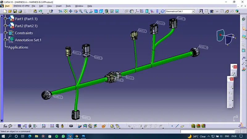
Harness A
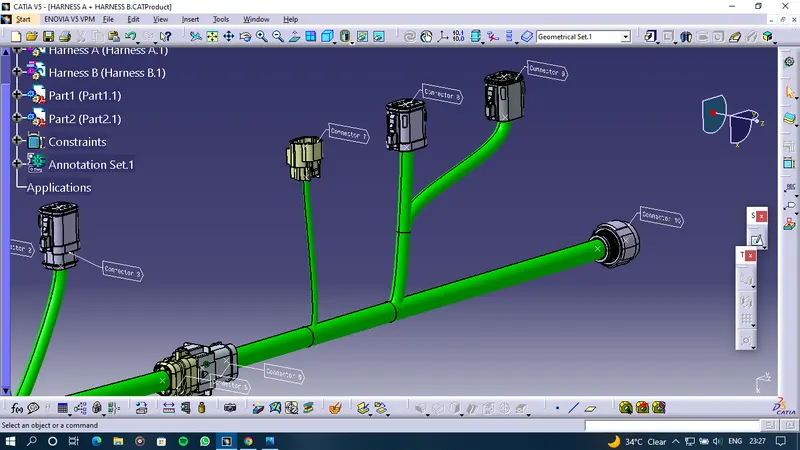
Harness B
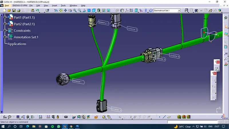
- The continuity of the Bundle is checked whether the bundle is connected or not to do that set the attribute criterion as FASLE
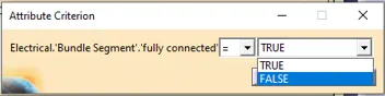
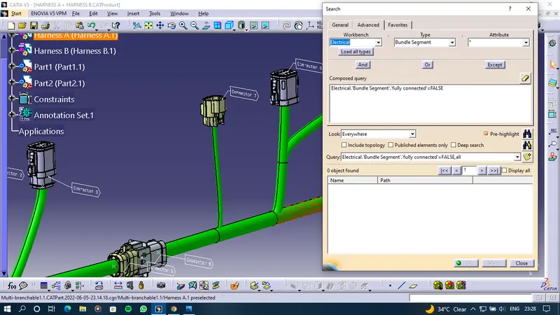
As we can see there is no object found in the check as we set the criterion as false in the conclusion that all the bundle segments are fully connected.
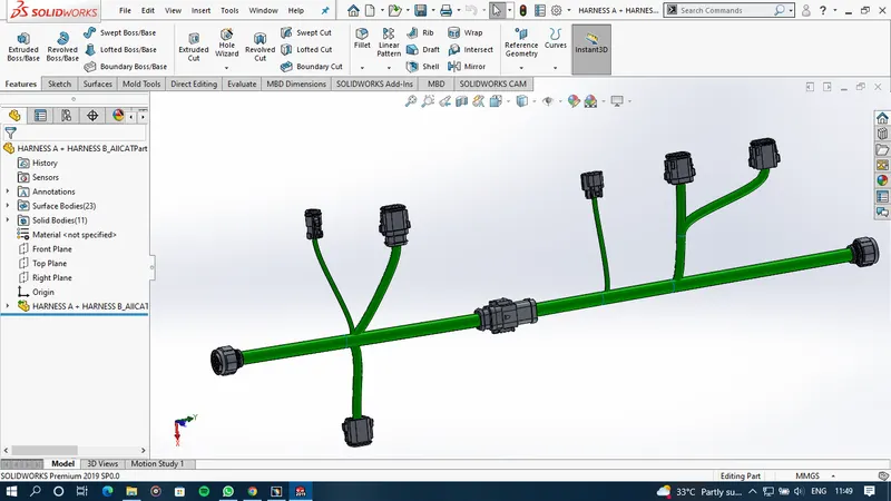
Finally to Generate the Product as CATpart Generate CATpart from product command is used in the Tool section to make this product into the IGES (.igs) format.
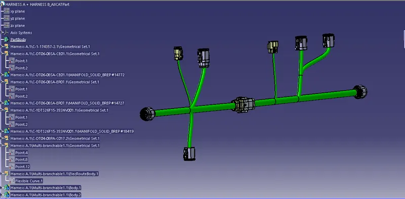
Creating the product file to IGES or STEP file help to open this product in any other CAD Software like SOLIDWORKS, NX CAD, CREO etc.
Following is the example of SOLIDWORKS after importing the IGES file into it