Roof challenge
Aim- To develop the essential flanges and reinforcements with appropriate dimensions and check the draft by performing Draft analysis, Calculating Section inertia, Heat distortion and Snow load on the roof.
Roof- An automobile roof or car top is the portion of an automobile that sits above the passenger compartment, protecting the vehicle occupants from sun, wind, rain, and other external elements.
In later years, many variations on the automobile roof developed. These include:
- Convertible roofs - A convertible or cabriolet is a passenger car that can be driven with or without a roof in place. The methods of retracting and storing the roof vary between models. A convertible allows an open-air driving experience, with the ability to provide a roof when required. Potential drawbacks of convertibles are reduced structural rigidity (requiring significant engineering and modification to counteract the effects of removing a car's roof) and cargo space.
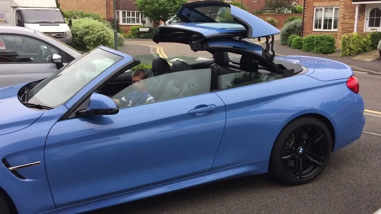
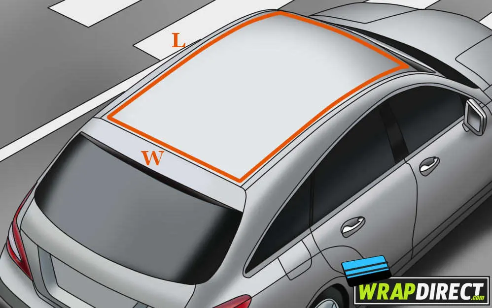
- Hardtops - A hardtop is a rigid form of automobile roof, which for modern cars is typically constructed from metal.
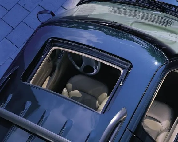
- Sunroofs - A sunroof is a movable panel that opens to uncover a window in an automobile roof, allowing light and/or fresh air to enter the passenger compartment. Sunroofs can be manually operated or moto, and are available in many shapes, sizes and styles. While the term sunroof is now used generically to describe any glass panel in the roof, the term "moonroof" was historically used to describe stationary glass panes rigidly mounted in the roof panel over the passenger compartment. A moonroof has a glass panel that is transparent and usually tinted. Previous terms include Sunshine Roof, Sliding Head and Sliding Roof.
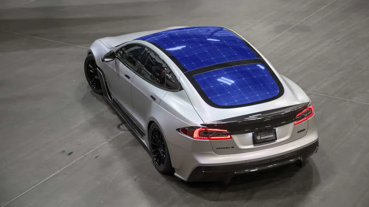
- Solar Panel Roof- The Solar panel roofs are newly developed for electric cars, to charge the batteries by using sunlight without stopping at charging stations which consume a good time to recharge the batteries. So that the solar panel roofs were developed for ongoing recharging of batteries.
The roof is designed by following some criteria-
- Visibility criteria as safety and functionality
- Head clearance for ease and comfort
- Draft analysis for easy manufacturing and tooling
- Safety parameters for users
- Heat distortion
- Snow load criteria
To create the Roof Given data is-
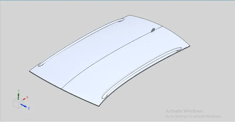
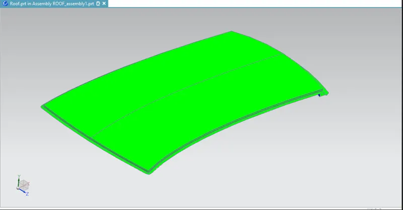
Roof Skin
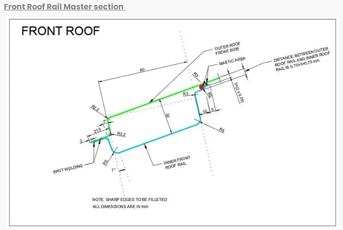
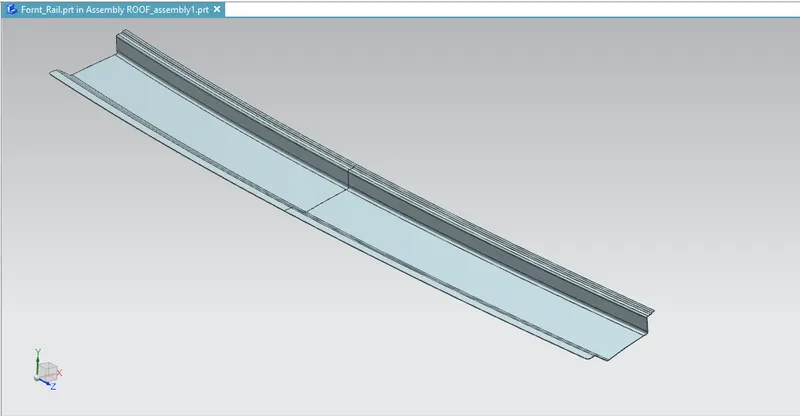
Front Roof Rail View
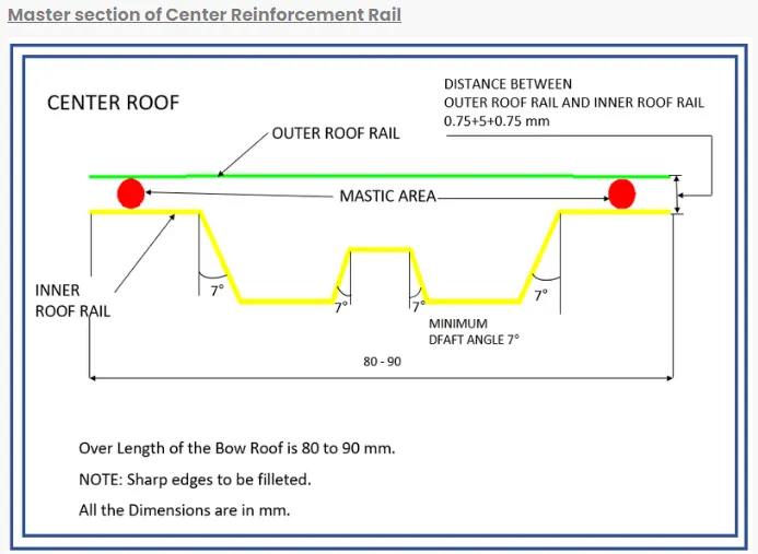
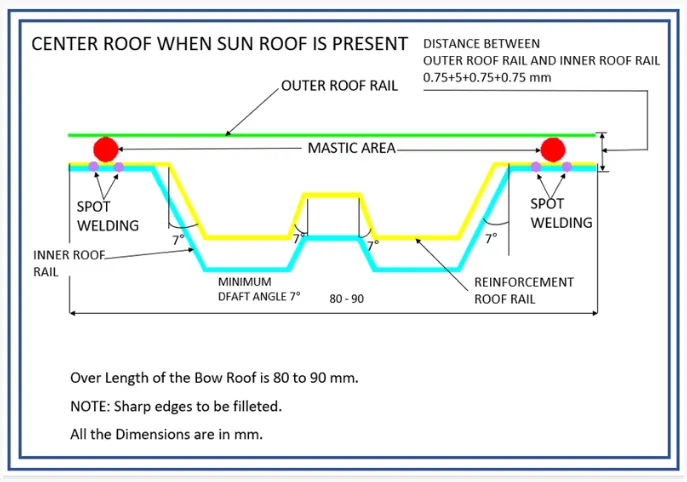
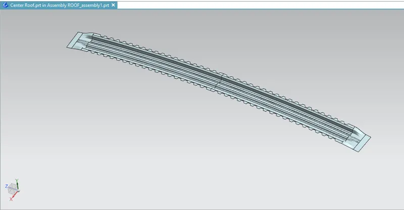
Center Roof Rail View
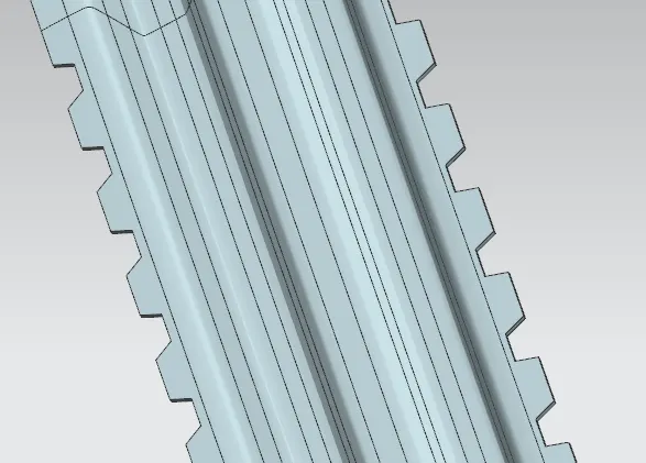
Side Flanges on Bow Roofbuilted/created for Mastic Sealant application\
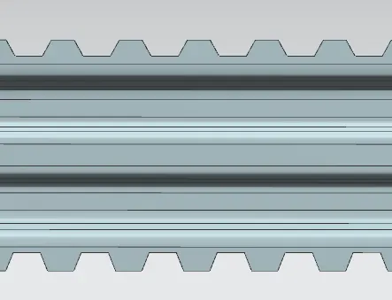
Center and Reinforcement Roof Rail Intersection View
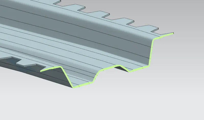
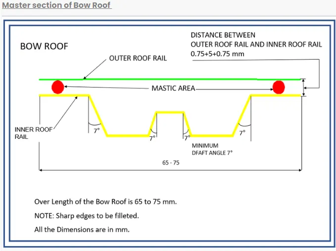
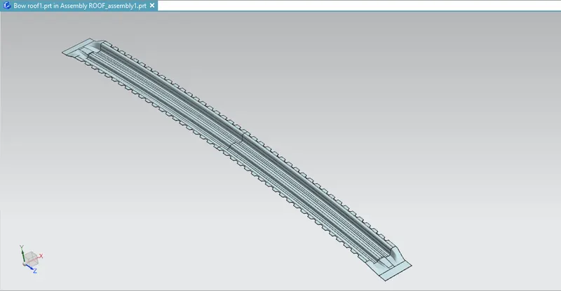
Bow Roofs View
Mastic Sealant application point is created
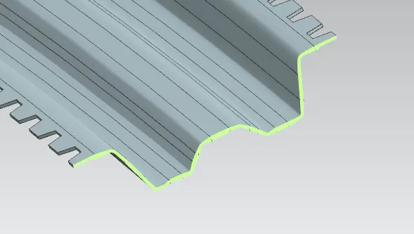
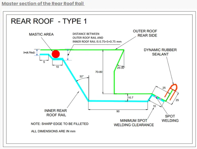
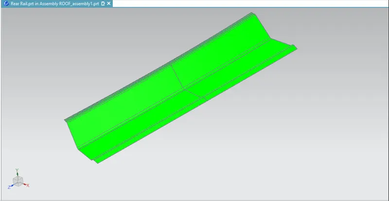
Rear Roof Rail View-
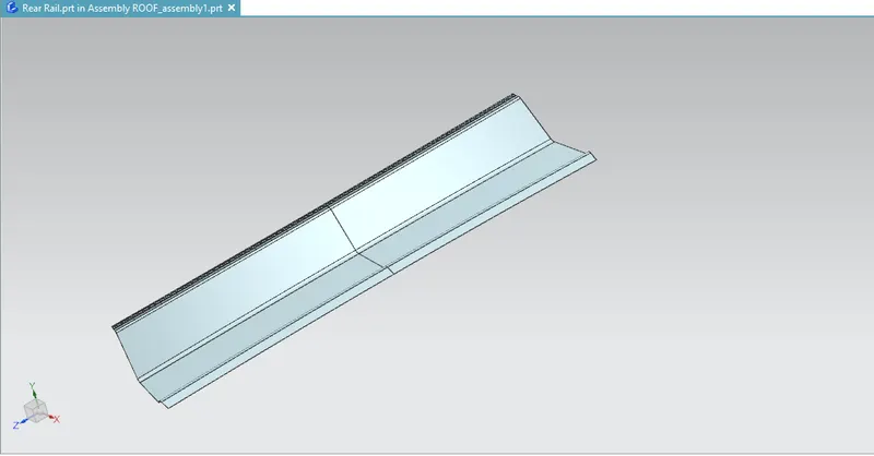

Roof Rails Position
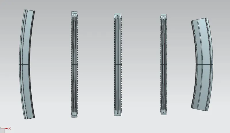
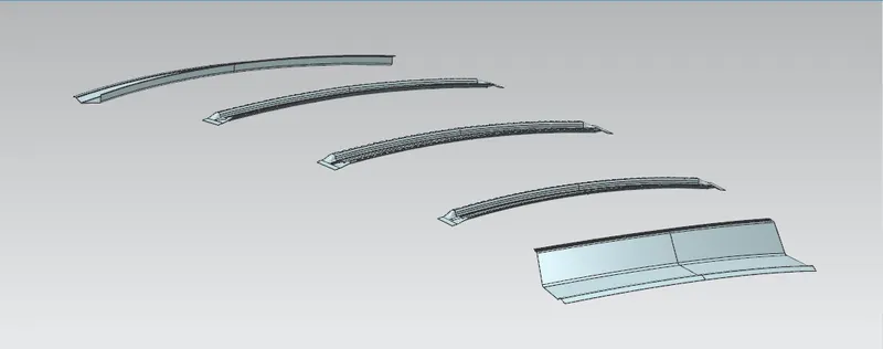
Outer Panel Flanges are created
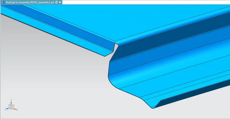
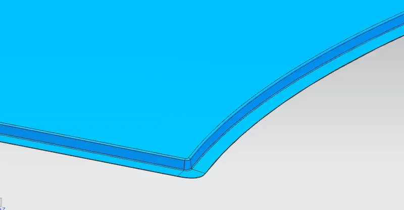
Rear Flanges are created in which backdoor hinges will position and backdoor will sit over it.
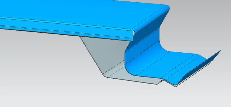
Complete Assembly View
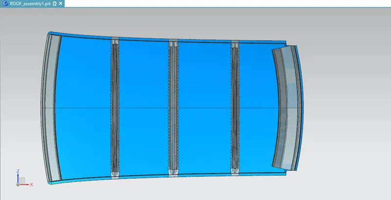
After completing the desaren there is some calculations cae done us to calculate the strength of the Designed Roof.
Roof Bow Calculations
Heat Distortion Calculation
W = [1.73 x 10^(-3) x L] + [1.85 x 10^(-8) x (R^2)/t] + [ 1.10x10^(-3) x l] - 2.68
Judgement Condition : OK< 2.7> 3.1
Where
L = Roof Length in X-Direction[mm](Roof dimension in 0-Y)
R = Roof curvature
R = 2(Rx*Ry)/(Rx+Ry)
Rx = X curvature
Ry = Y curvature
t = Roof plate thickness [mm]
l = Bow Roof Span [mm]
Except for Rx and Ry, all values can be measured on the model.
To get the Rx and Ry curvature a sketch was required-
- A sketch was created on a plane on top of the Roof
- The 0-Y line was created in the X-Direction in the centre of the roof
- Then a Horizontal line below 300mm was created named as -3Y Line
- Two lines on both sides at 100mm were created from -3Y Line
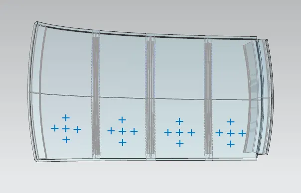
- An intersection point online was created and projected on the outer Panel of the Roof
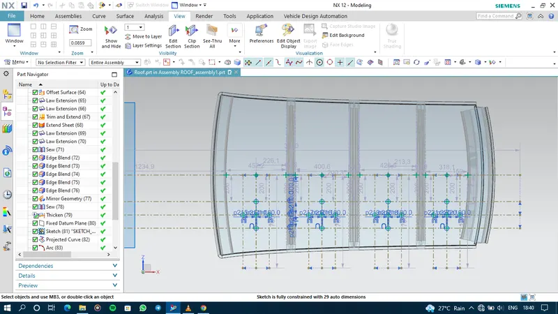
Projected Points
Then Three point Arc was created by using these points
Then Minimum Radius of curvature was measured to get the Rx and Ry Value
RX 1 Value Obtained
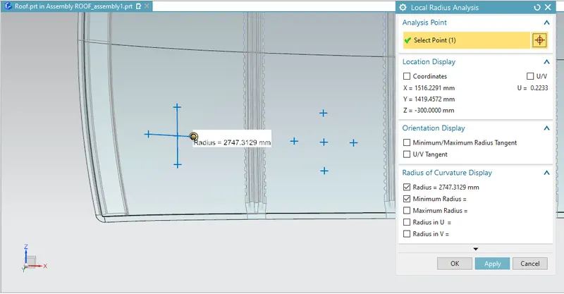
RY 1 Value Obtained
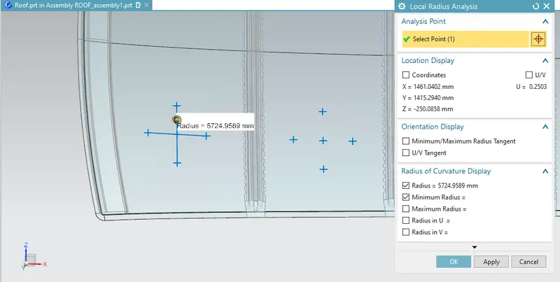
RX 2 Value Obtained
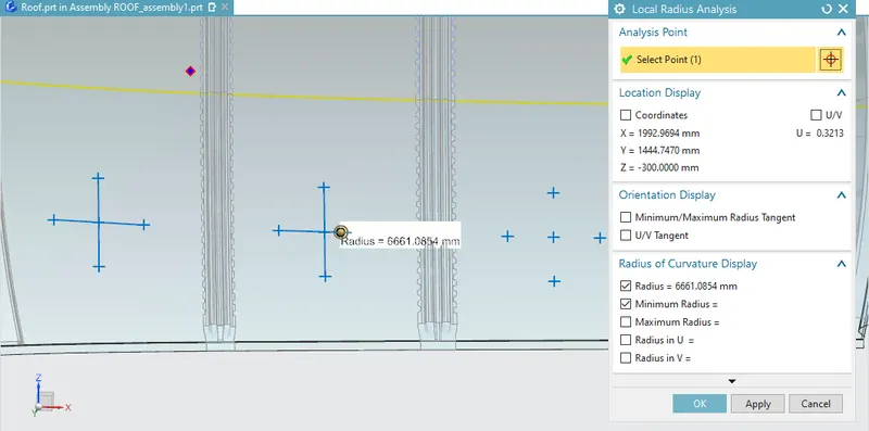
RY 2 Value Obtained
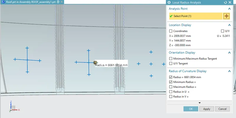
RX 3 Value Obtained
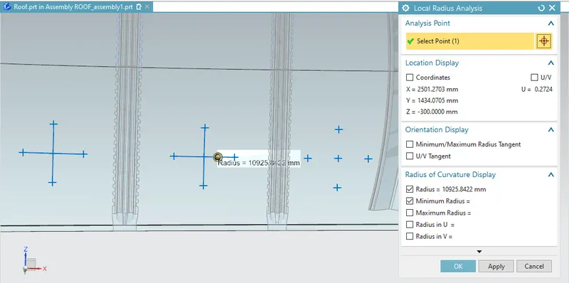
RY 3 Value Obtained
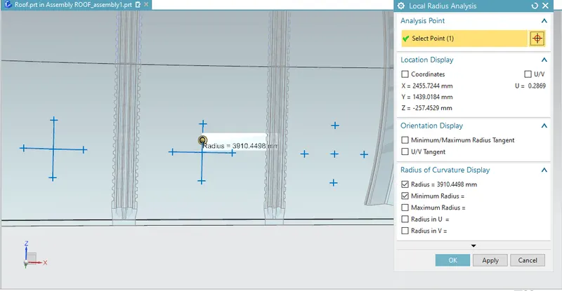
RX 4 Value Obtained
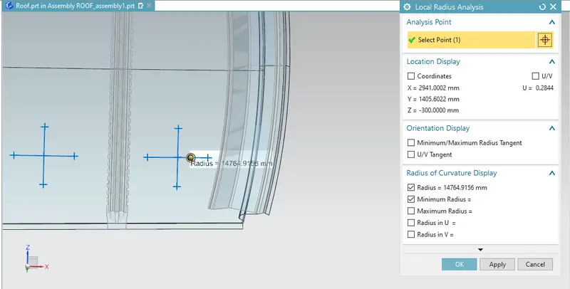
RY 4 Value Obtained
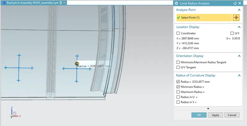
By using all Values Heat Distortion was Calculated in the MS Excel

Snow Load Calculation
During Winter Season the snow gets clogged over the top surface/roof of the car and the snow has some mass on it. Due to this, the roof can fail if the snow load exceeds the capacity of the roof that was designed to sustain.
Snow load Prediction formula
Qr = [Iy x t2] / [α x s x [(Rx + Ry)/2]2 x 10-8]
Note: The Qr value given over here is correct. There was a typo error in the formula given in the video.
Where
α = My x Lx2 x 10-12 , My = Y(Ly-Y)
Judgement condition = Qr ≥ 3.1
250 ≤ s ≤ 380
t = Roof plate thickness [mm]
Ly = Distance between the front and rear roof Rails on the Vehicle along with 0Y[mm]
Length of Roof panel to the centre point between Roof rail Front /Rear as the front and rear reference point.
Lx = Distance between the Left and Right end of the roof on the Roof BOW [mm]
The width of the rise of the panel is exposed on the surface.
Y = Distance front Front Roof Rail to Roof BOW[mm]
s = Distance for which Roof BOW bears divided load [mm]
s = L1/2 + L2/2
Iy = Geometrical moment of inertia of Roof BOW (Y cross-section )[mm4]
Rx = Lateral direction curvature radius of roof panel Y cross-section on Roof BOW [mm]
Roof panel curvature Radius of the Length Lx in Front view
Ry = Longitudinal Direction curvature radius of the Roof panel X cross-section on Roof BOW [mm]
Roof panel X curvature radius of length s in Side view
To get the values a sketch was created on top of the Roof
- O-Y line was created in the centre of the roof
- A line between the centre and centre Roof rail was created
- Then two lines on both sides at 100mm were created
- Similar lines were created between centre roof rails, both Bow Roof rails and rear roof rails
- Intersection points were created and projected on the roof
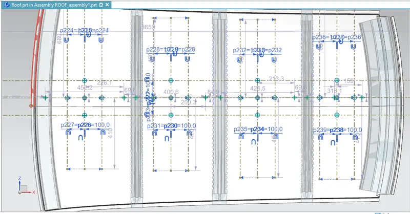
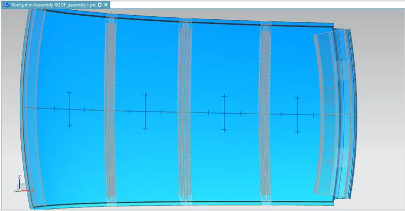
Rx 1 Value Obtained
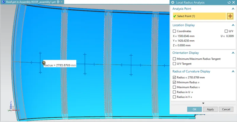
Ry 1 Value Obtained
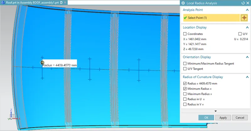
Rx 2 Value Obtained
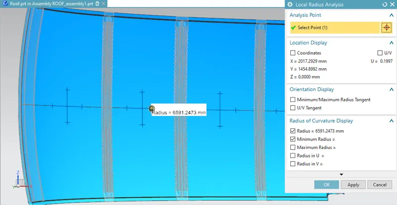
Ry 2 Value Obtained
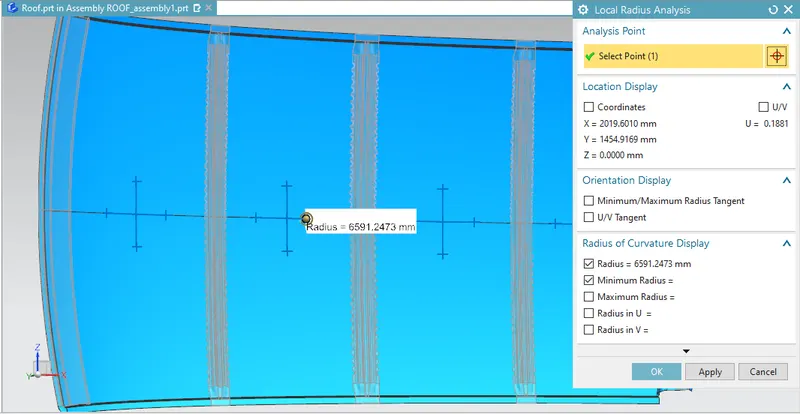
Rx 3 Value Obtained
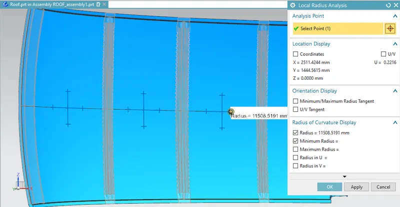
Ry 3 Value Obtained
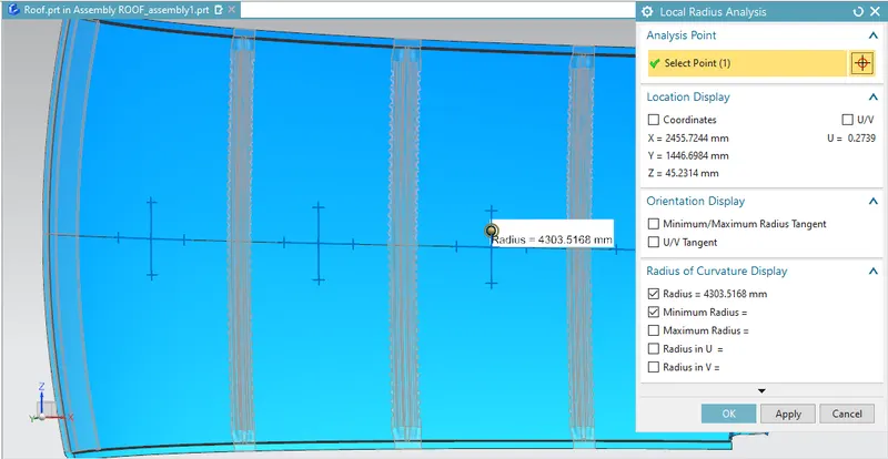
Rx 4 Value Obtained
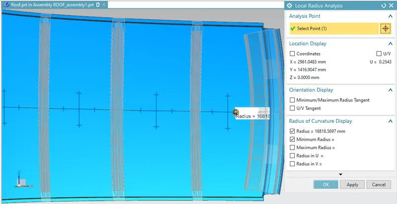
Ry 4 Value Obtained
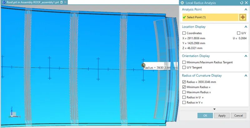
By using all the values Snow load was calculated in the MS Excel

Snow Load Calculation
So, according to the Judgement condition = Qr ≥ 3.1
And, Here one result of Qr is not fulfilling the demand. So, there are some solutions, that the model can pass over to the styling team to change the curvature to improve the strength, Bow Roof rails position can be changed to the weaker side of roof or Embosses could be created on the outer panel to improve the strength.
Section Modulus:
Section modulus is a geometric property for a given cross-section used in the design of beams. Other geometric properties used in the design include an area for tension, radius of gyration for compression, and moment of inertia for stiffness. The Section modulus is defined as
S=Iy
Where
S = Section Modulus
I = Moment of Inertia
y = Distance from the neutral axis to any given part.
Front Roof rail
The intersection was created and then the Section Inertia command was used to obtain MOI
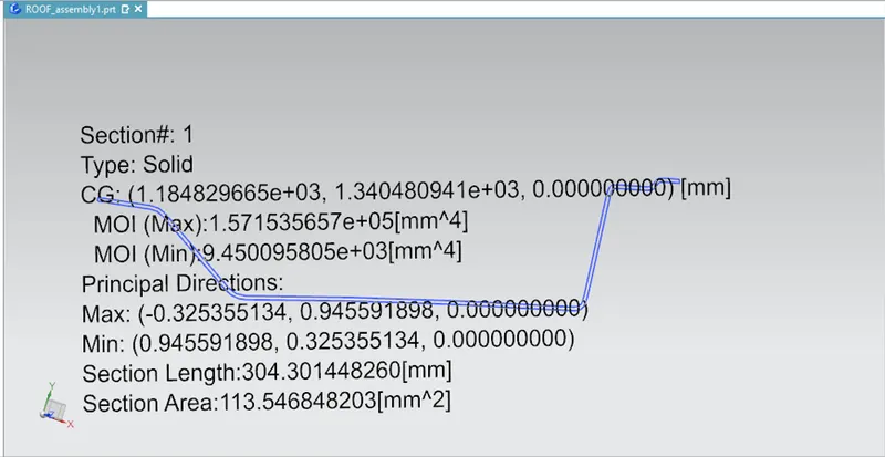
S=I/Y
I=9.45 x 10^3mm4
Y=124.46/2= 62.23
S= 151.85mm3
Center Roof rail
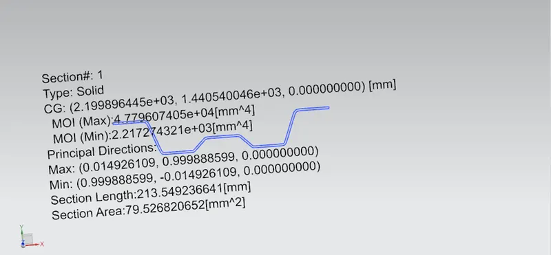
S=I/Y
I=2.12 x 10^3mm4
Y=84.94/2= 42.47
S=49.91mm3
1st Bow Roof and 2nd Bow Roof rail
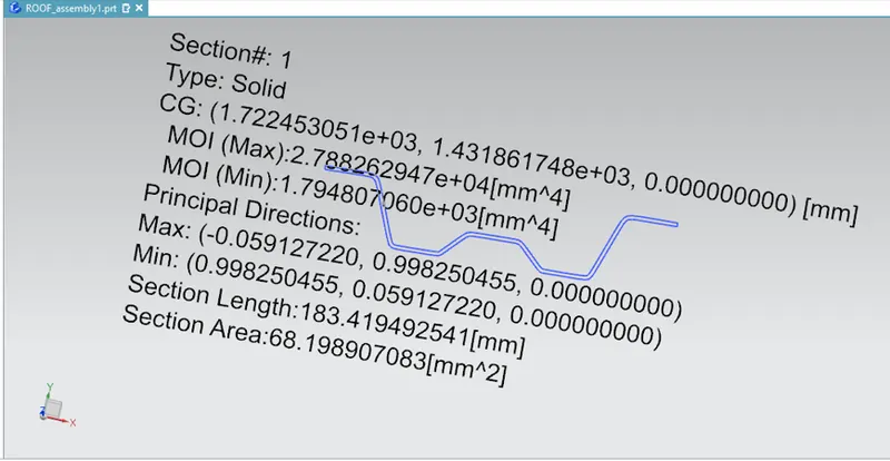
S=I/Y
I=1.79 x 10^3mm4
Y=69.92/2=34.96
S=51.20mm3
Rear Roof rail
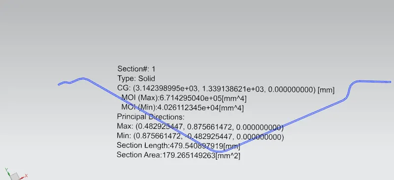
S=I/Y
I=4.02 x 10^3mm4
Y=192.16/2=96.08
S=41.8mm3
Draft Analysis
Draft analysis was performed with 7 Degrees Value(generally given in sheet metal)
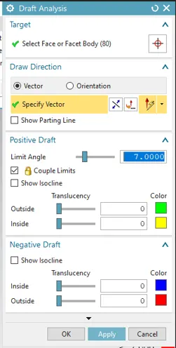
Front Roof rail
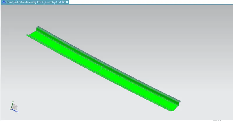
Center Roof rail
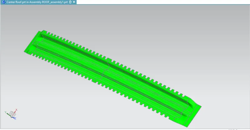
1st Bow Roof and 2nd Bow Roof rail
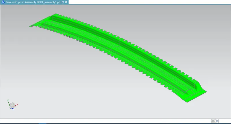
Rear Roof rail
Outer Panel
After Completing the Design there are a physical test of the vehicle is done to check the strength of the Roof of the vehicle.