WIRE BENDING SIMULATION
AIM:
- To perform wire bending simulation using ansys workbench.
- To evaluate equivalent stress equivalent elastic strain developed in the wire during the bending operation for three given non-linear materials those are aluminum alloy NL, Copper alloy NL, and magnesium alloy NL.
PROCEDURE:
- Open ansys workbench.
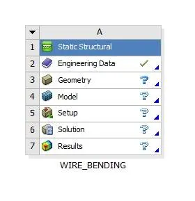
- Create a static structural analysis system and rename it as wire_bending.
- Double click on engineering data to add Copper Alloy (Non-Linear), Aluminium Alloy (Non-Linear), and Magnesium Alloy (Non-Linear) material to the library.
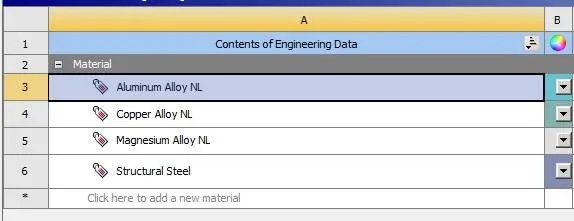
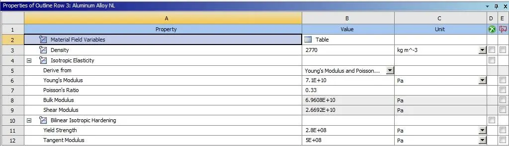
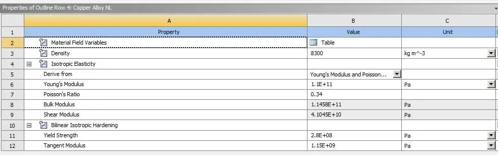
MATERIAL PROPERTIES AS BELOW:
ALUMINIUM ALLOY NL:
COPPER ALLOY NL :
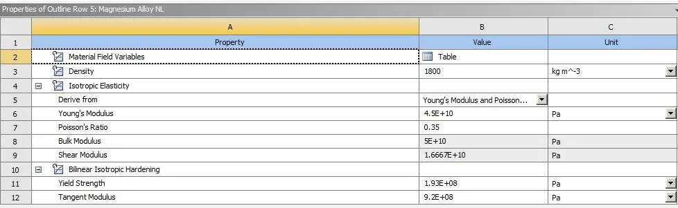
MAGNESIUM ALLOY NL :
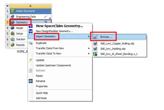
- Import geometry by browsing to the file location.
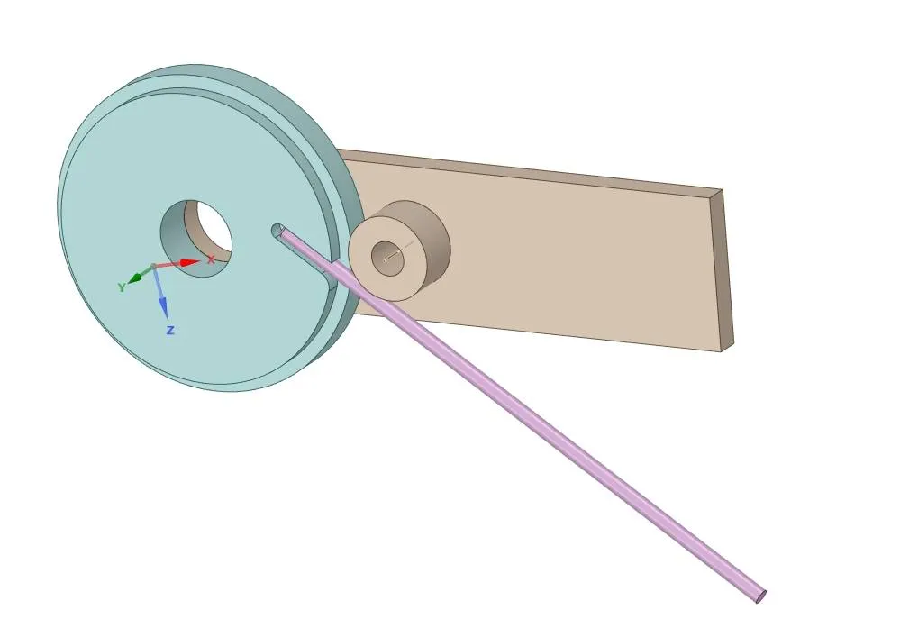
- Open geometry using SpaceClaim and check for abnormalities, and close the SpaceClaim and update the project.
- Open ansys mechanical rename the geometry as require.
- Change the material for the wire as Copper Alloy (Non-Linear).
- Go to connections and right-click on the contact group and click on rename based on the definition.
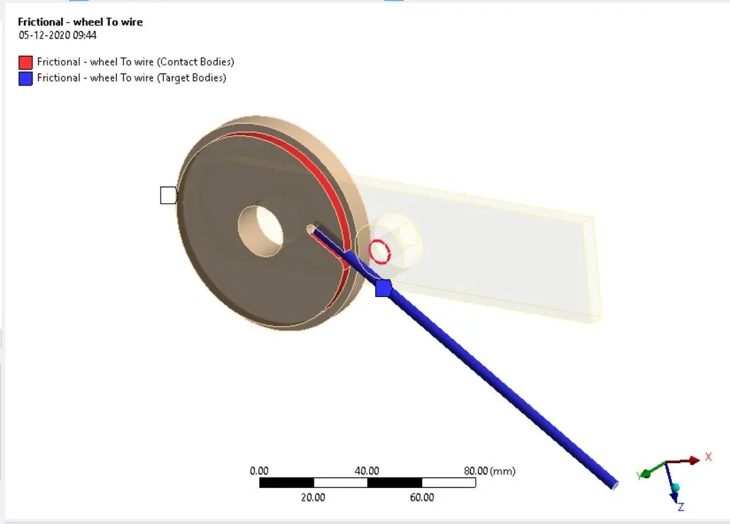
- Delete all the contact and create the contacts between wire and lever and wheel to wire as below.
- Change contact type to frictional with a coefficient of friction of 0.2 and change formulation to augmented Lagrange and update normal stiffness by a factor of 0.1 and update stiffness for each iteration.
- Change interface treatment to add offset, ramped effects.
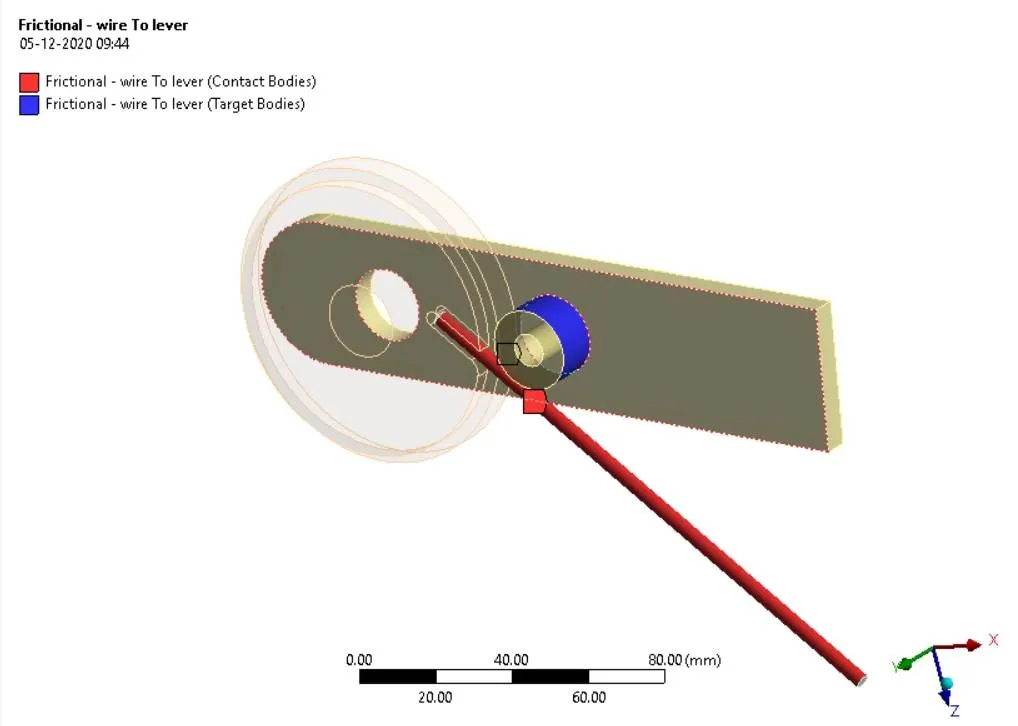
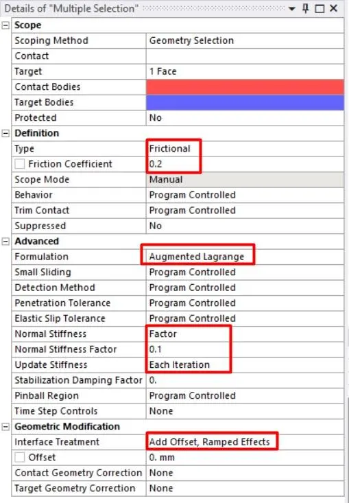
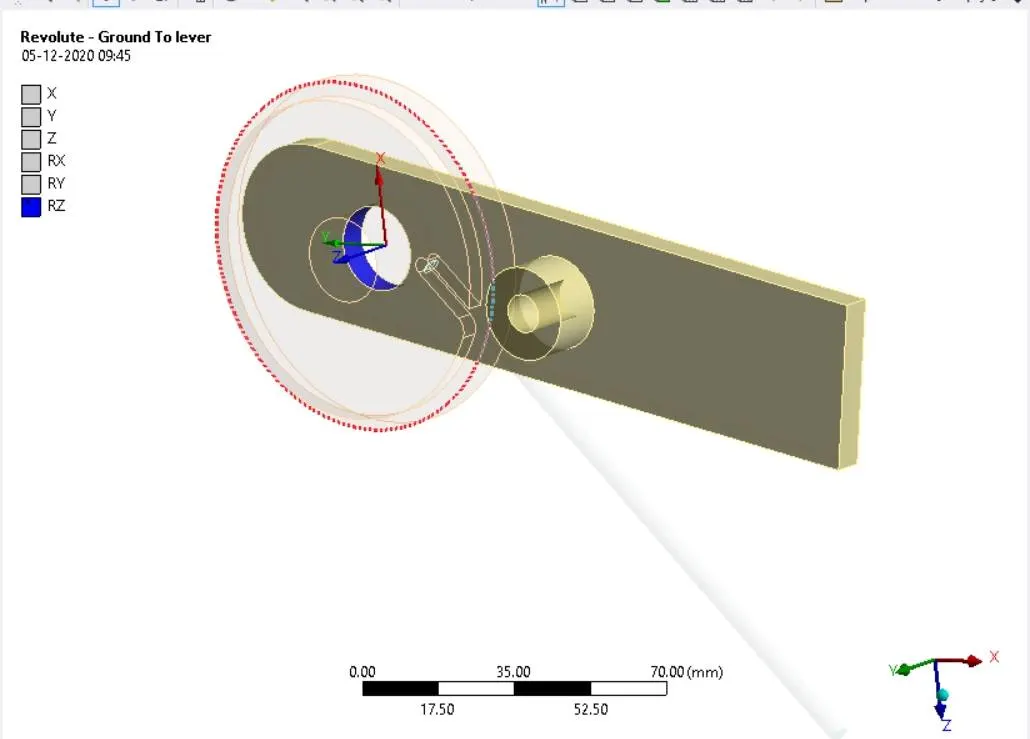
- Now create a revolute joint for the lever as below.
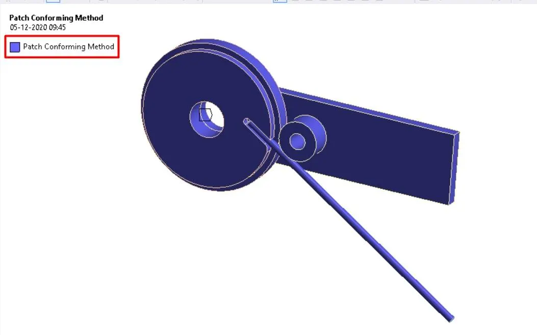
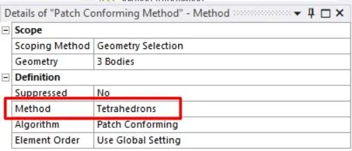
- Now mesh the component by inserting the mesh method for the three geometries as shown below. Change the method to the tetrahedrons.
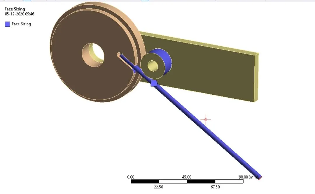
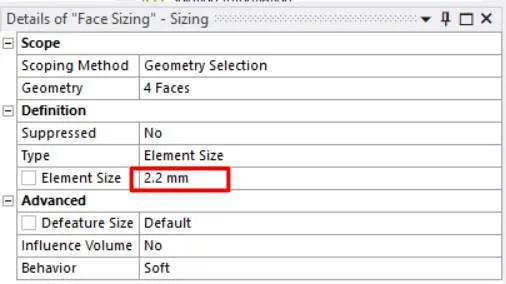
- Insert face sizing for the contact surfaces with an element size of 2.2 mm.
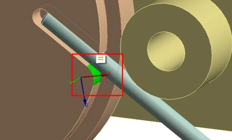
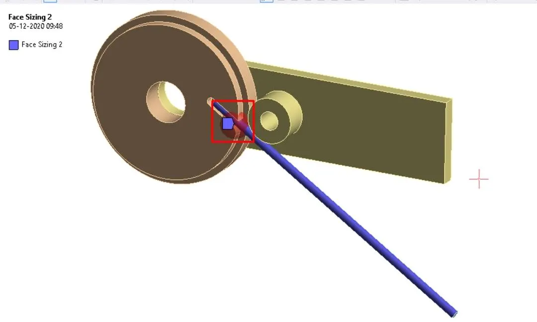
- Create a coordinate geometry for the below surface and offset it along x about 3mm and offset the axis along z-axis about -3mm.
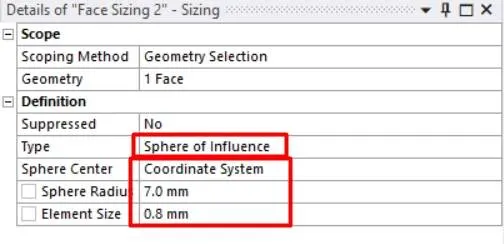
- Insert face sizing and change type to the sphere of influence and sphere center which is created above.
- Change the sphere radius to 7.0 and element size to 0.8mm.
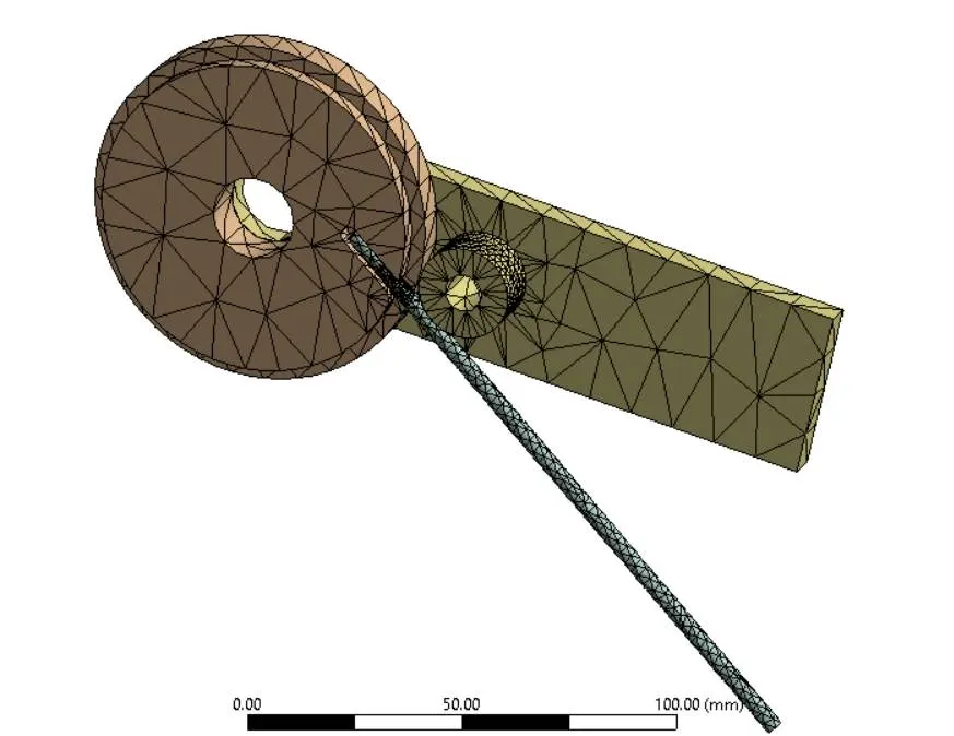
- Right-click on the mesh and generate the mesh.
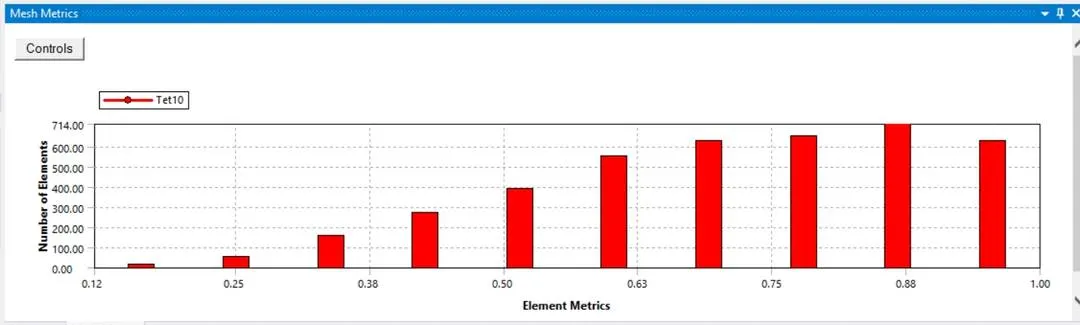
- The above graph represents the mesh metrics which gives mesh quality and element type.
- Now change the analysis setting change number of steps to 8 and turn on the auto time-stepping and change the analysis settings for step-1 as below. change solver type to direct and turn on the large deflection. Change all the output controls to yes.
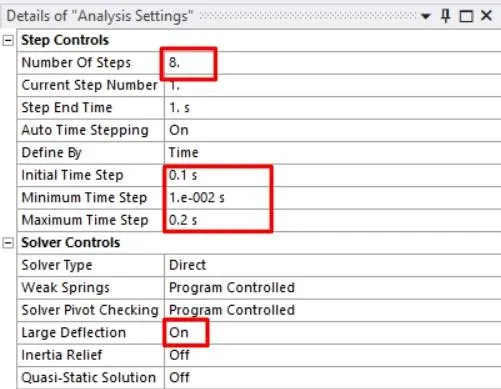
- Now select the steps2-8 and change the analysis setting as below.
- Create fixed support for the wheel and the end of the wire as shown below.
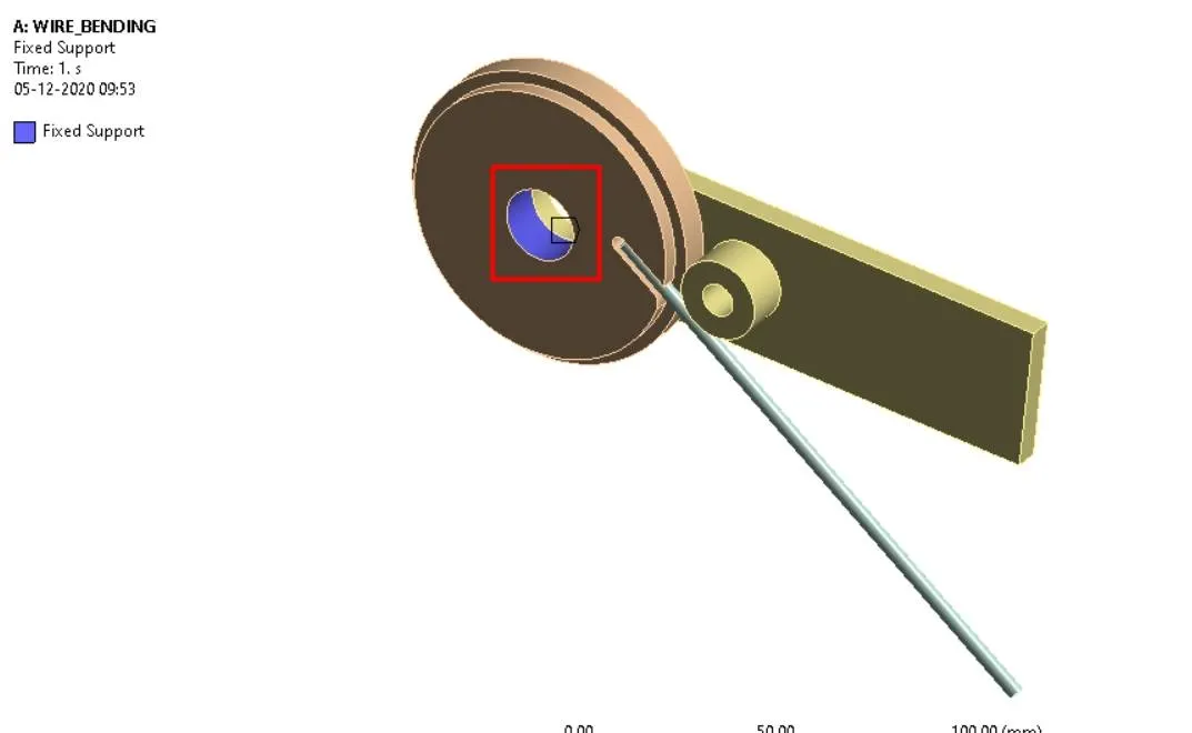
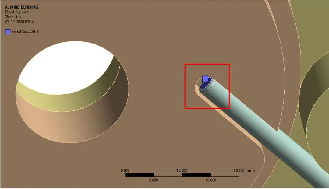
- Insert the joint rotation in tabular data as below.
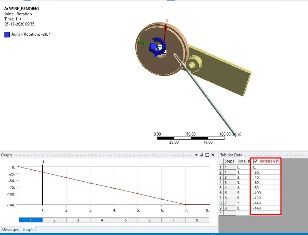
- Insert the outputs i.e. equivalent stress and equivalent strain in the wire in the solutions tab and solve for the results.
- Repeat the same procedure for all the three different materials.
- For magnesium, alloy NL change the auto-time stepping to program-controlled and run the simulation.
RESULTS:
CASE-1: FOR COPPER ALLOY NL
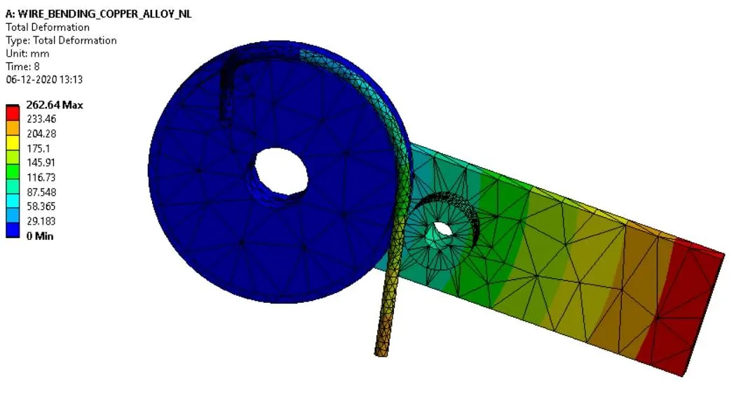
TOTAL DEFORMATION:
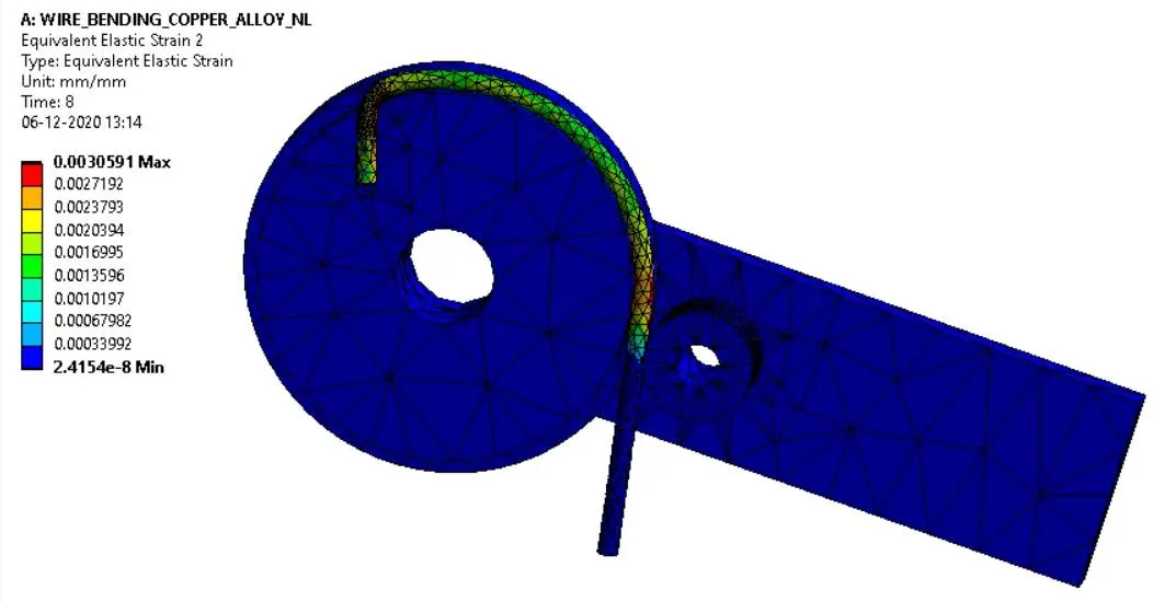
OVERALL EQUIVALENT STRAIN:
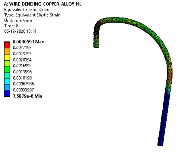
EQUIVALENT STRAIN IN WIRE:
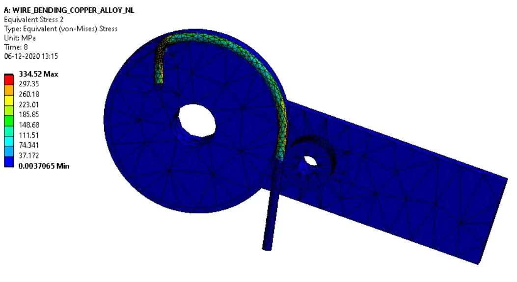
OVERALL EQUIVALENT STRESS:
EQUIVALENT STRESS IN WIRE:
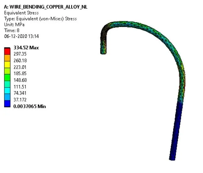
CASE-2: FOR ALUMINUM ALLOY NL
TOTAL DEFORMATION:
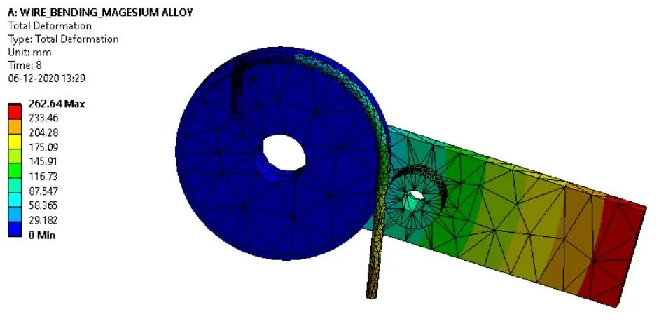
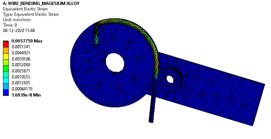
OVERALL EQUIVALENT STRAIN:
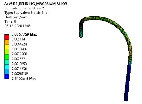
EQUIVALENT STRAIN IN WIRE:
OVERALL EQUIVALENT STRESS:
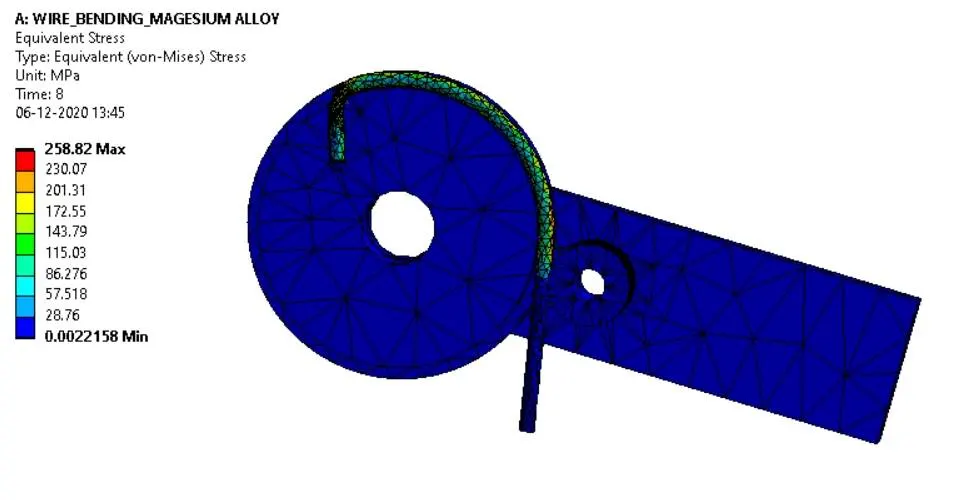
EQUIVALENT STRESS IN WIRE:
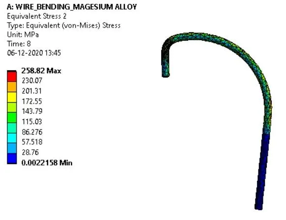
CASE-3: FOR MAGNESIUM ALLOY NL
TOTAL DEFORMATION:
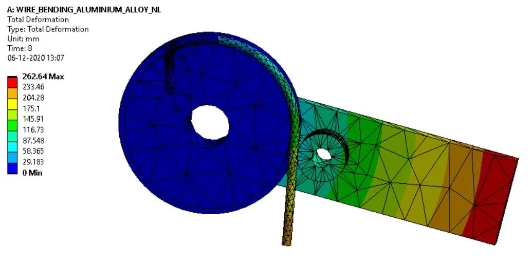
OVERALL EQUIVALENT STRAIN:
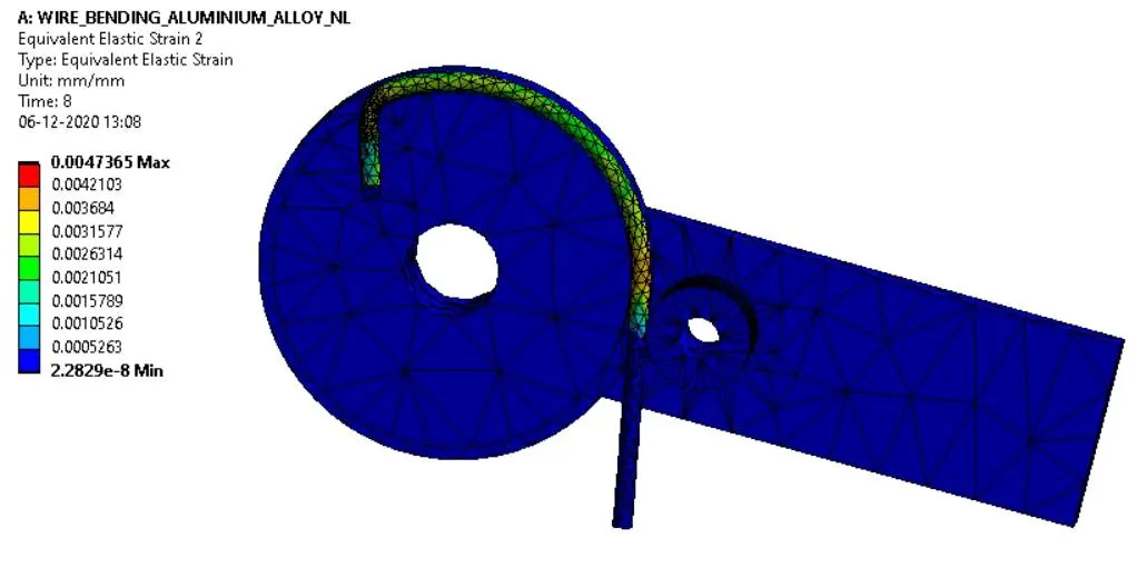
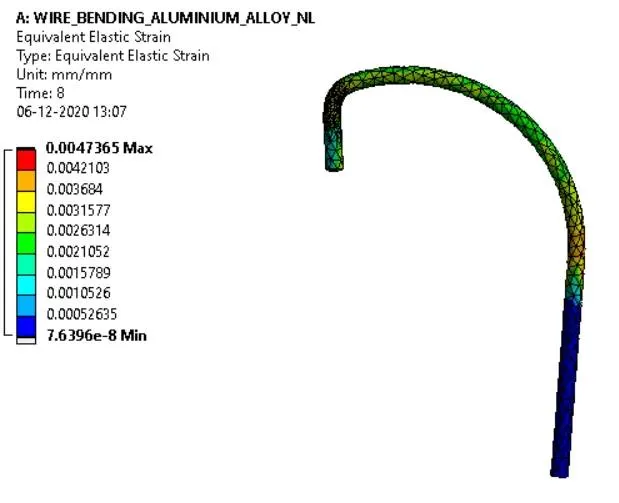
EQUIVALENT STRAIN IN WIRE:
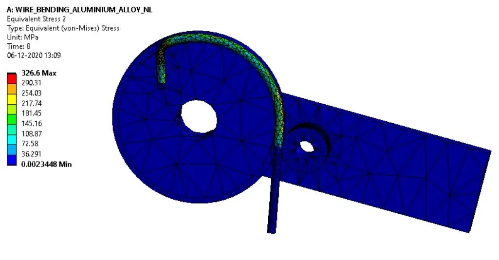
OVERALL EQUIVALENT STRESS:
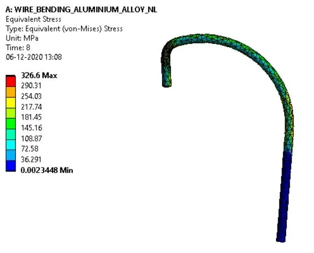
EQUIVALENT STRESS IN WIRE:
| SL.NO | MATERIAL | EQUIVALENT STRAIN IN WIRE | EQUIVALENT STRESS IN WIRE |
| 1 | COPPER ALLOY NL | 0.0030591 | 334.52 MPa |
| 2 | MAGNESIUM ALLOY NL | 0.0047365 | 326.6 MPa |
| 3 | ALUMINIUM ALLOY NL | 0.0057759 | 258.82 MPa |
CONCLUSIONS:
- The wire bending simulation for the given three materials is performed successfully.
- The simulation results are tabulated.
- The deformation in all three materials is the same and the equivalent strain for the copper is less compared to aluminum alloy and magnesium alloy.
- The equivalent stress in aluminum is less than in copper alloy and magnesium alloy.
- Hence the copper and aluminum are suitable for wire bending operation.