Week 6
AIM and Objective:
- To create a proper connection for the given FE model using Nastran DECK.
- To assign the PID and materials for the weld connection and respective PID's for the created connections.
Procedure:
1. Import FE model.
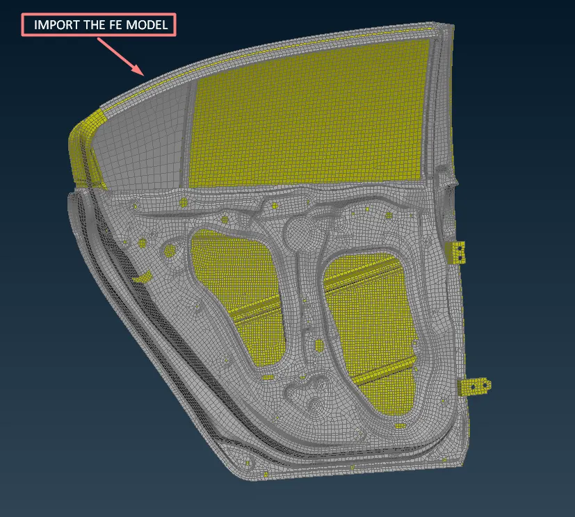
2. First, create the connection between the weather liner and glass using CBUSH elements because the CBUSH elements have stiffness in all directions.
3. Hide all the unwanted components For creating the CBUSH connection.
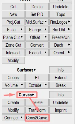
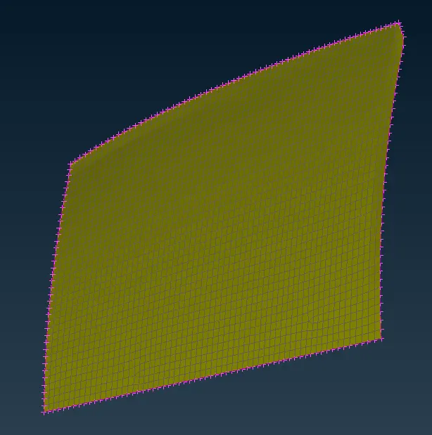
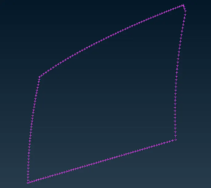
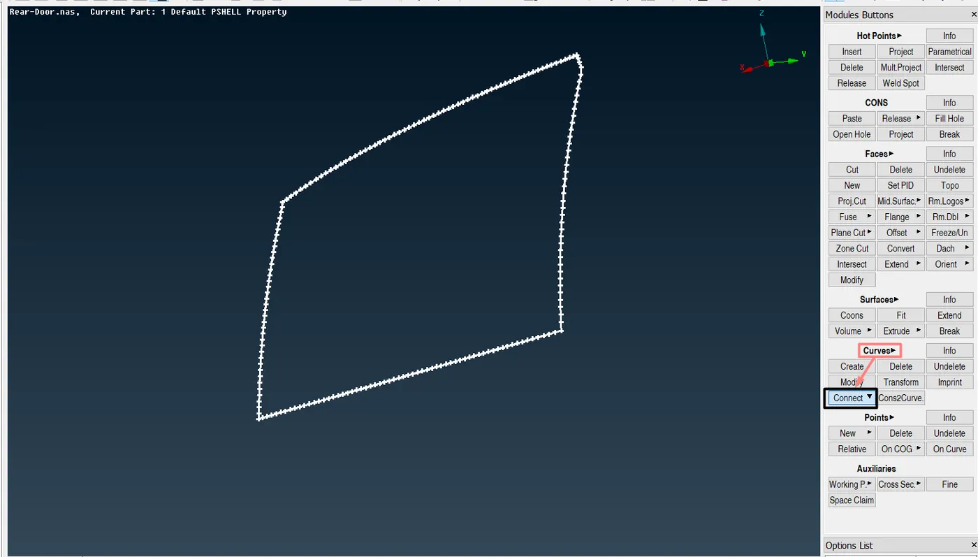
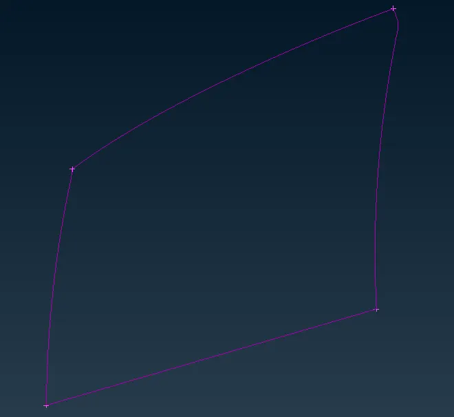
4. Go to curves and cons2curve and convert the edges to curves.
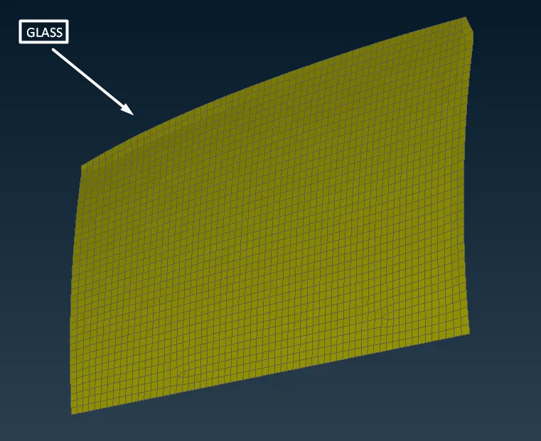
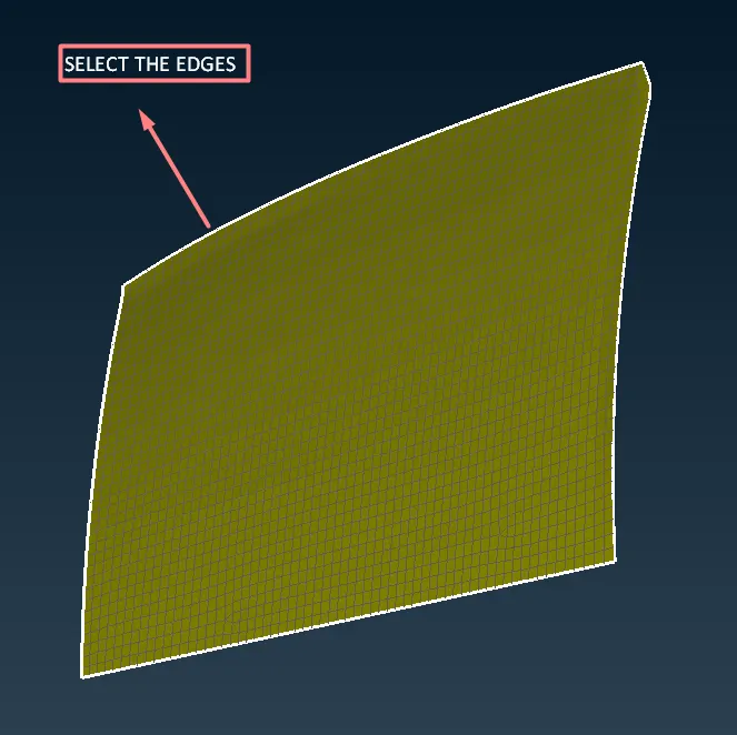
5. Select the edges as shown in the above picture and covert them as curves as shown in the below picture.
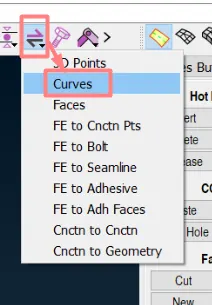
6. Convert the above curves to SPOT LINES to create connections using convert under assembly manager.

7. Select the curves option under convert.
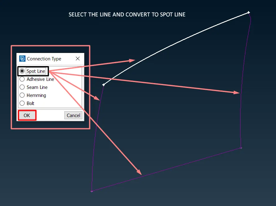
8. Select the lines one by one and convert them to spot lines.
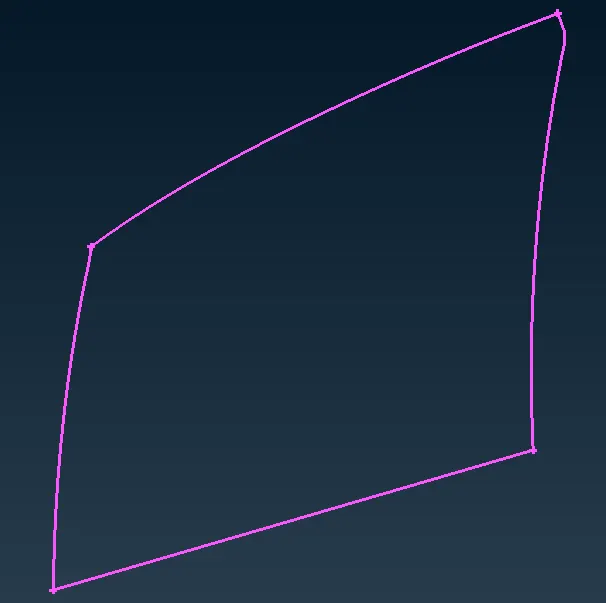
9. After converting the curve to spot line create connections using connection selection assistant.

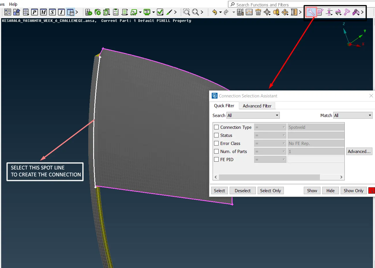
10. After selecting the spot line connection manager will opens.
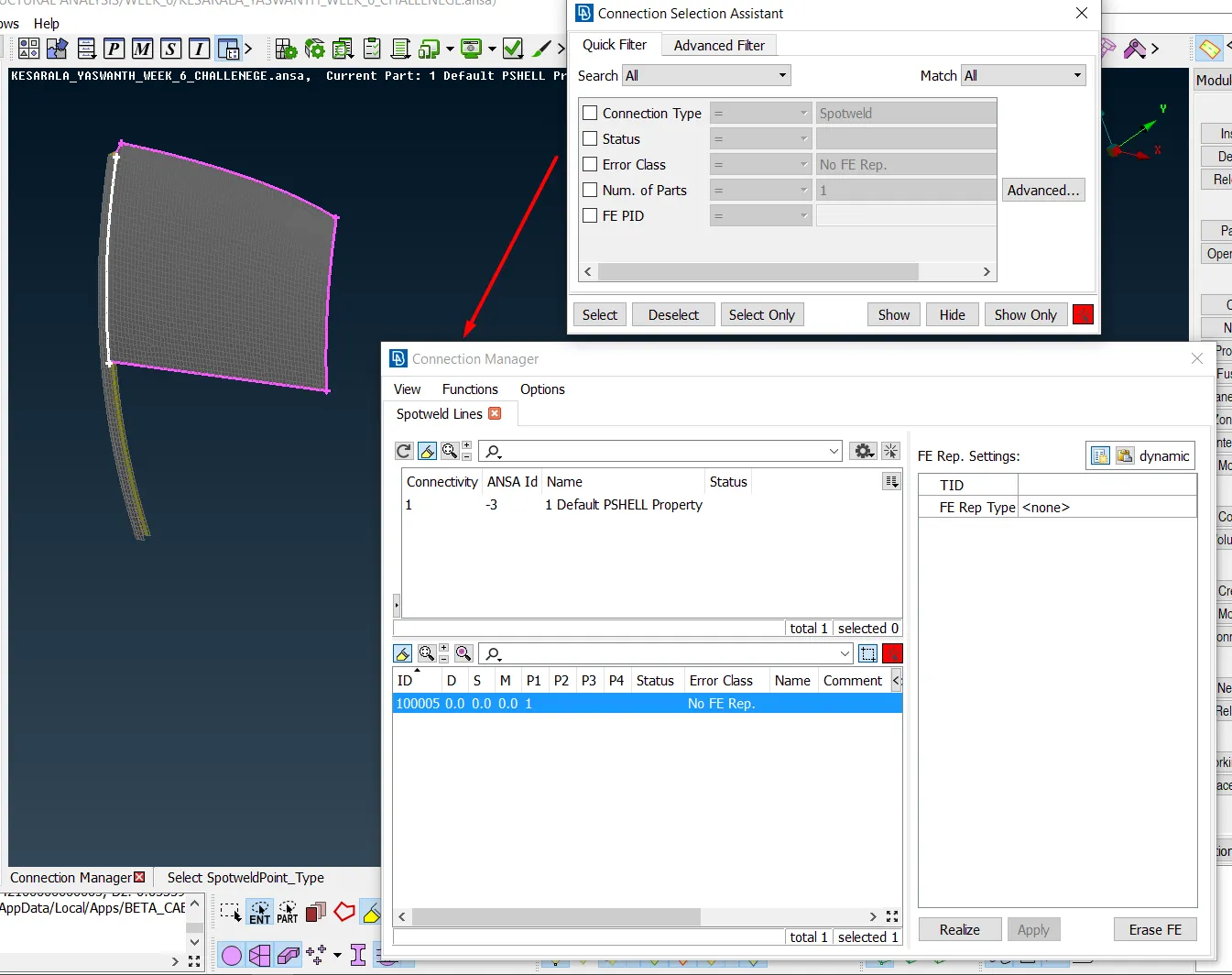
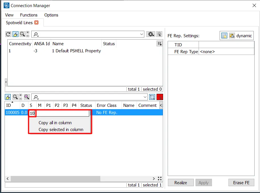
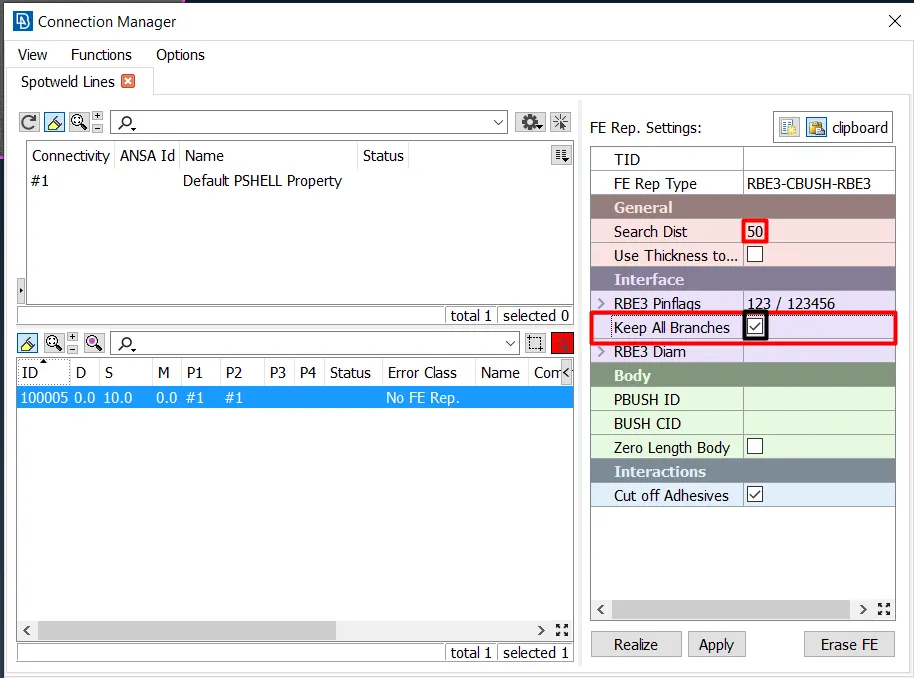
11. Give the spacing as 10, and assign P1 and P2.
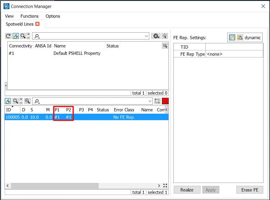
12. After assigning P1 and P2 change Ferep type in the left window of the connection manager to RBE3-CBUSH-RBE3.
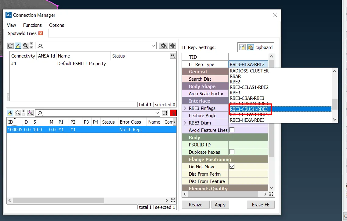
13. Give search distance give checkmark for keep all branches.
14. Create a new PBUSH id to assign the property.
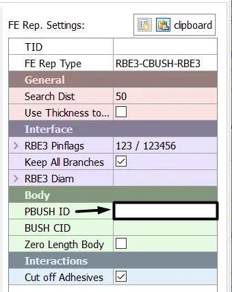
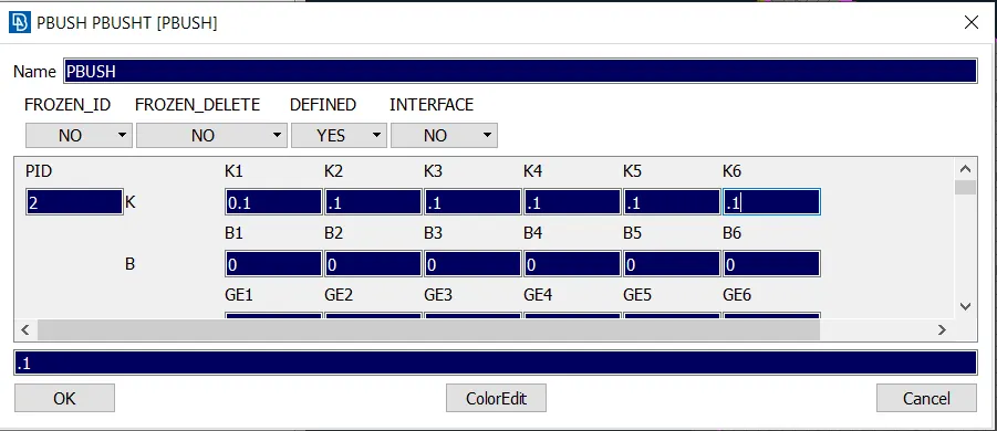
15. After creating a new PBUSH ID apply and realize the connection between the glass and weather liner will be created.
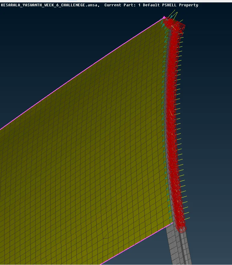
16. Repeat the same procedure for all the edges of the glass to create the connection on all sides.
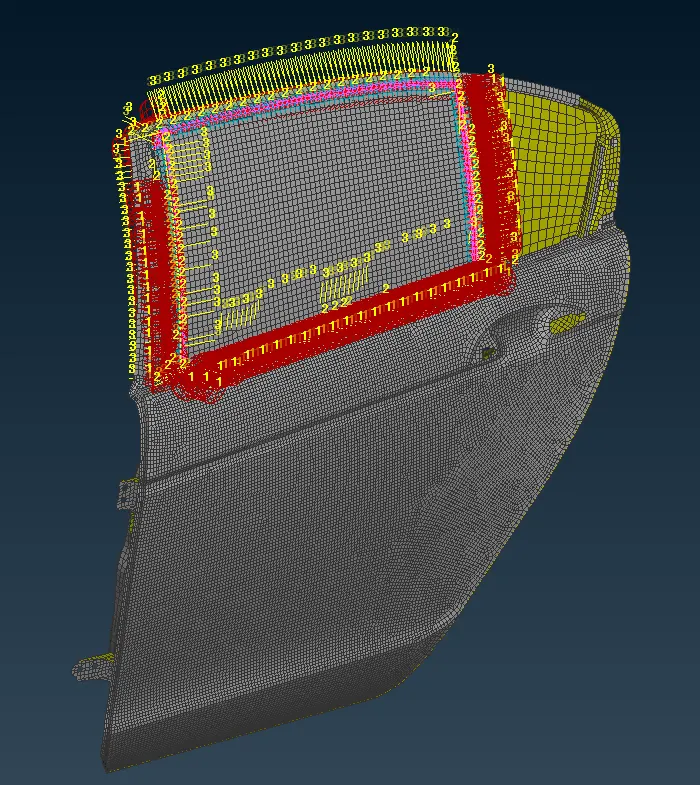
17. The created CBUSH elements are oriented with local co-ordinate so they have to be changed to respective global co-ordinated.
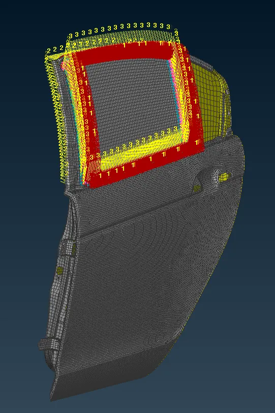
18. The above picture shows that all the PBUSH elements are oriented properly.
19. Now make connection for door handle and assign mass to it.
20. As to accommodate the door handle holes are provided on the door so first, we have to create RBE2 element over the holes as below.
- Switch to NATRAN go to elements and select RBE2 many node.
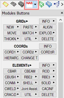
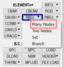
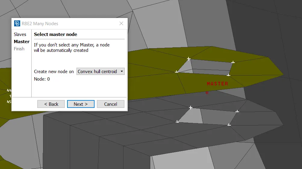
- Select nodes as shown below picture which is the perimeter of the hole these nodes will act as slave nodes.
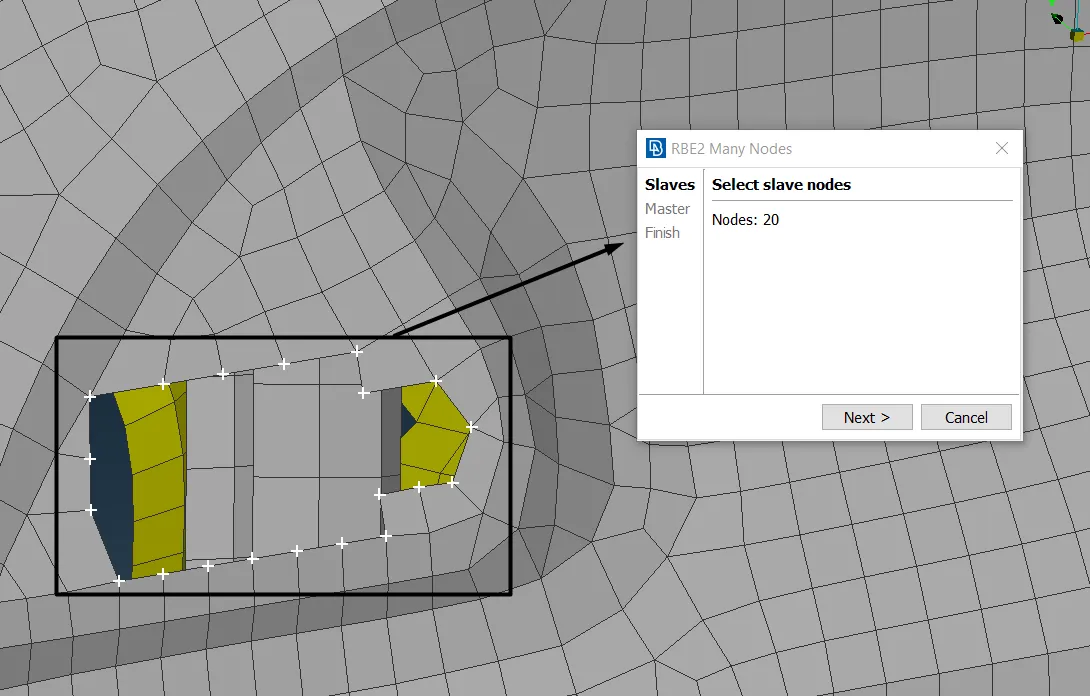
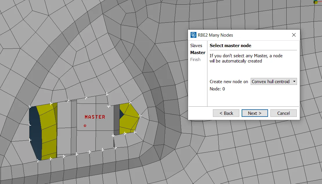
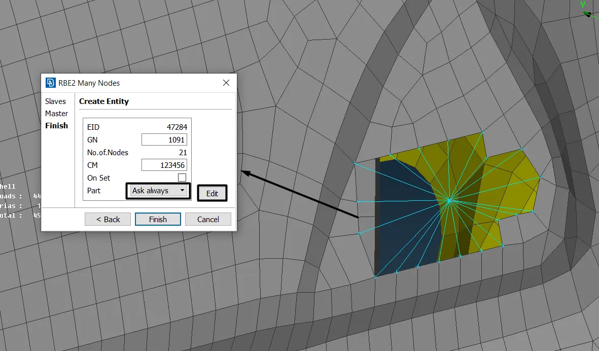
- While creating RBE2 elements make sure that part is kept to always ask. Because grouping will be easier.
- Define the part and create a new connection group.
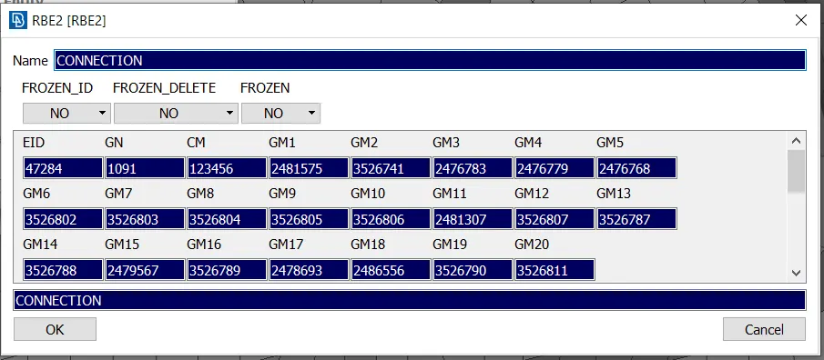
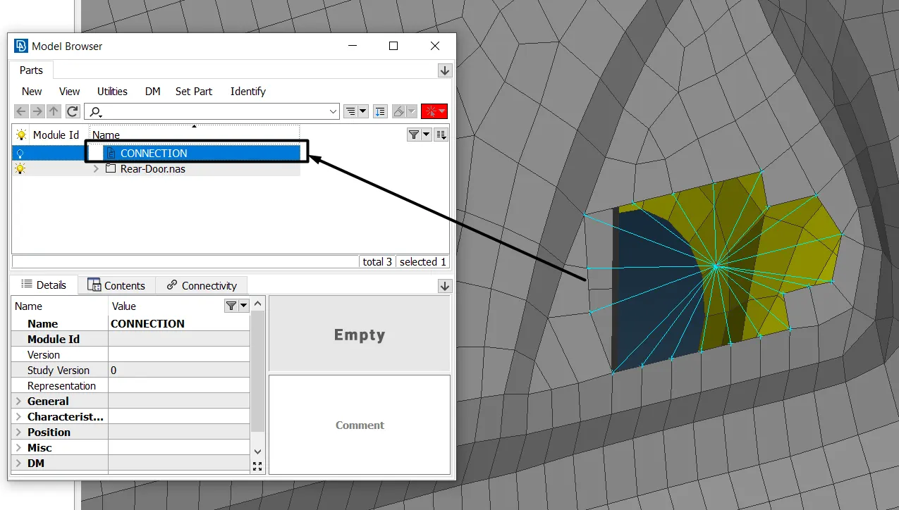
- Repeat the same steps to create the RBE2 element on another hole and connect the master nodes of the two holes using another RBE2 element as shown below picture.
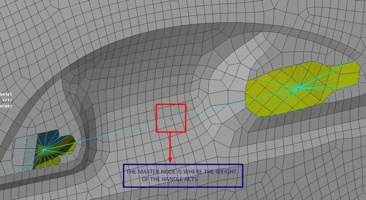
- The mass of the handle will act at the center master node. Assign the mass at the node by clicking on INFO.
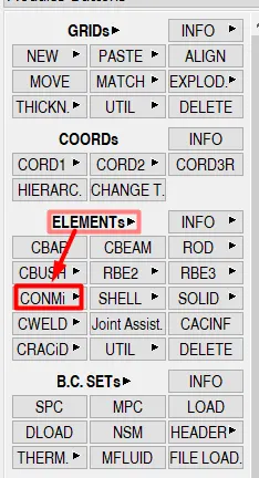
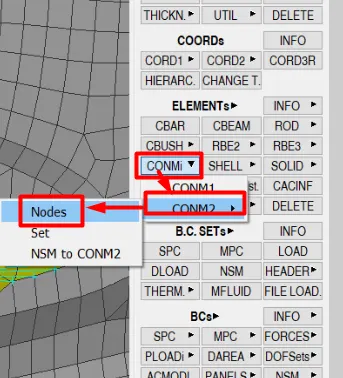
- In ansa, we have to give mass in terms of tonnes so if we assume the mass of the handle is 100gms assign the mass as o.ooo1 tonnes
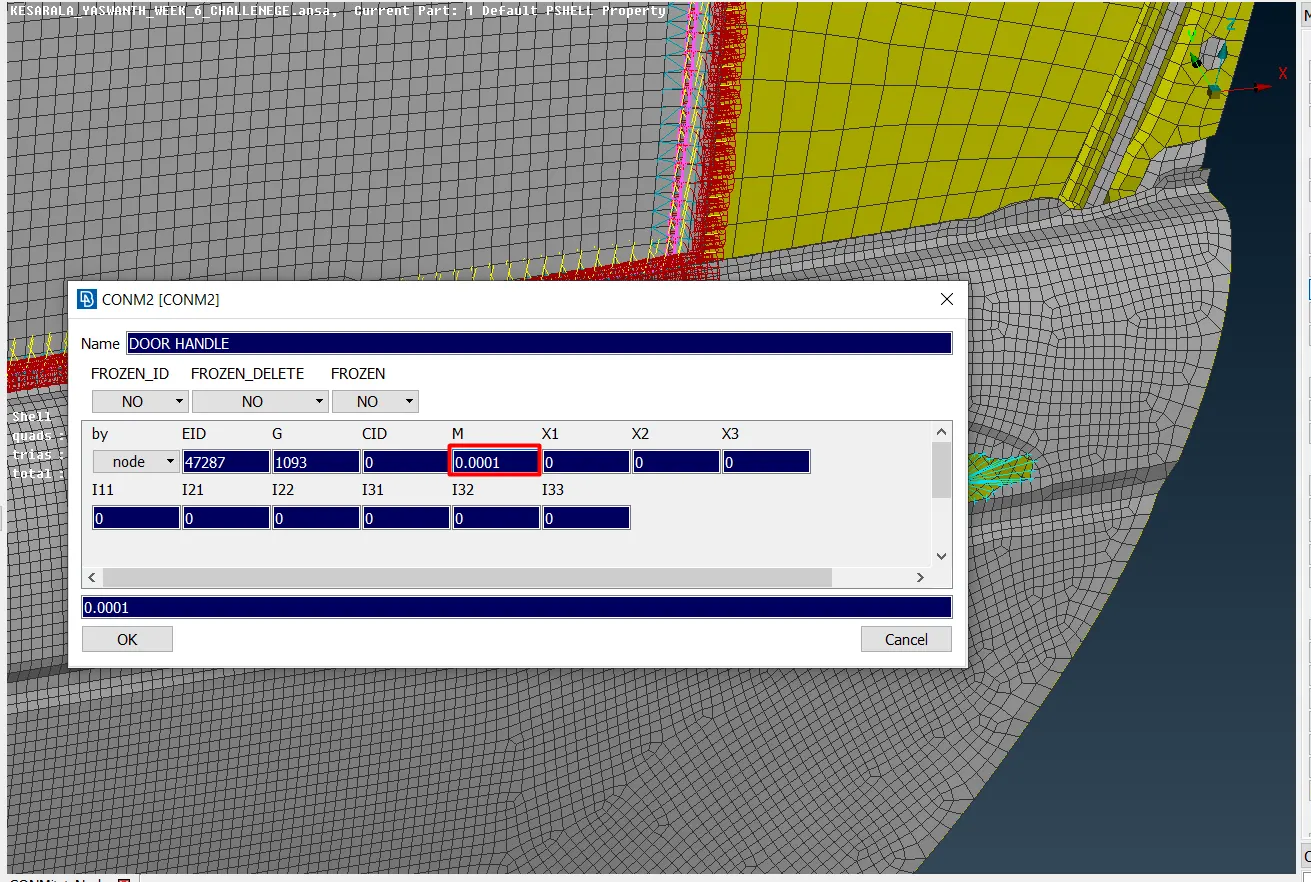
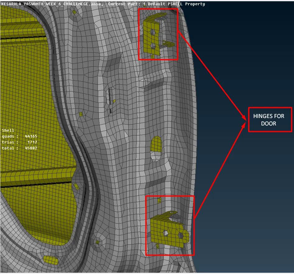
21. Now we create the connections for door hinges as we know that doors will open and close so that we have to create the RBE2 and we have to make changes in the degree of freedom to realize the connection.
- The door and the hinge are connected with the bolted joint so we can use either cluster node or 2 RBE2 elements with one stem two-node RBE2.
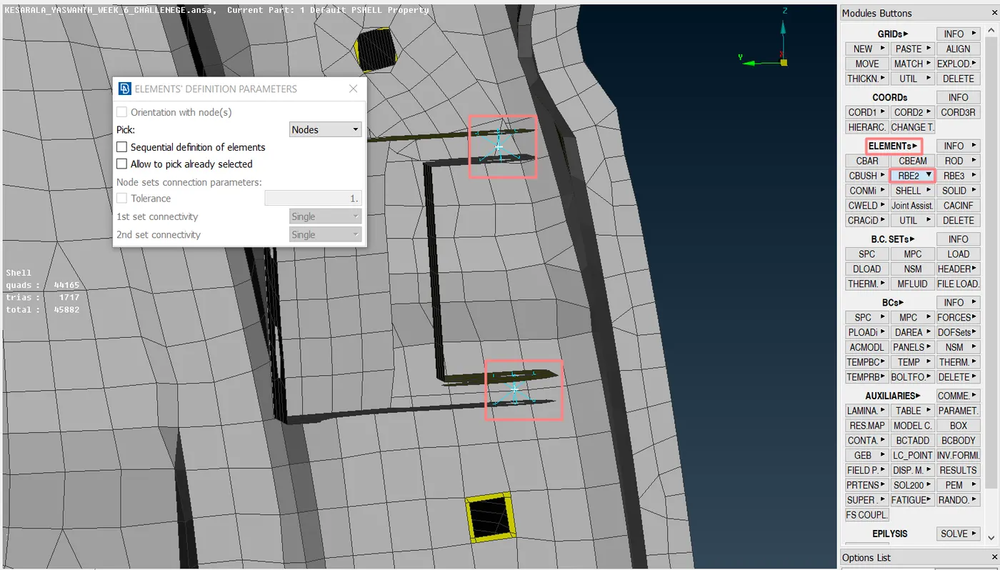
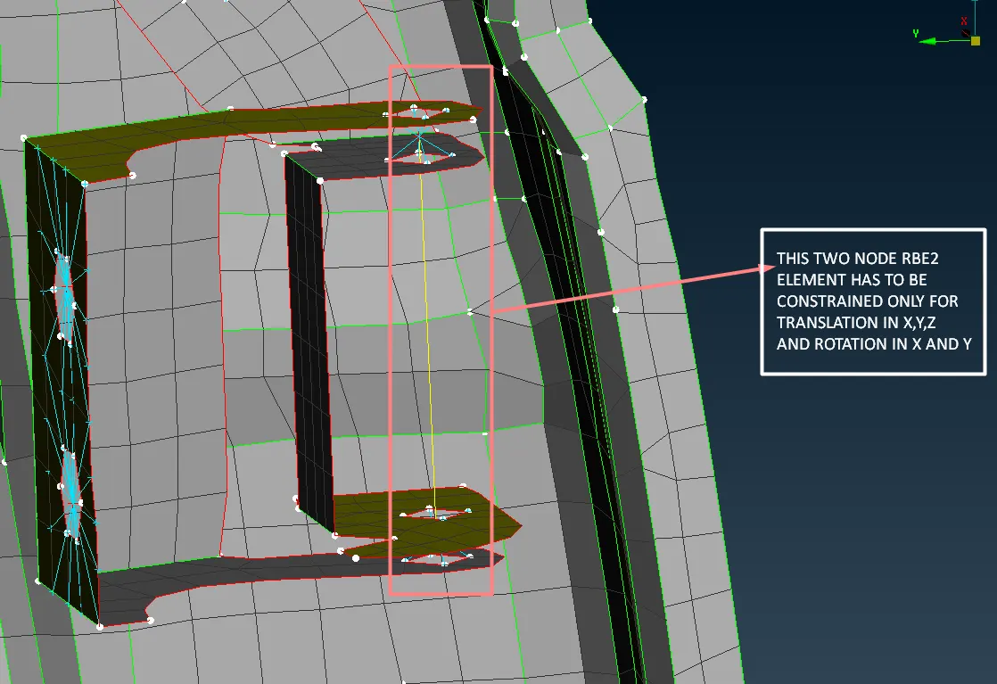
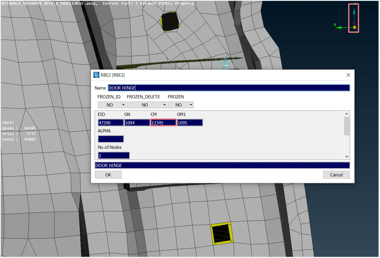
- In the above picture 12345 represents that the translation along x,y,z, and rotation along x and y are constrained and it is free to rotate along the z-direction.
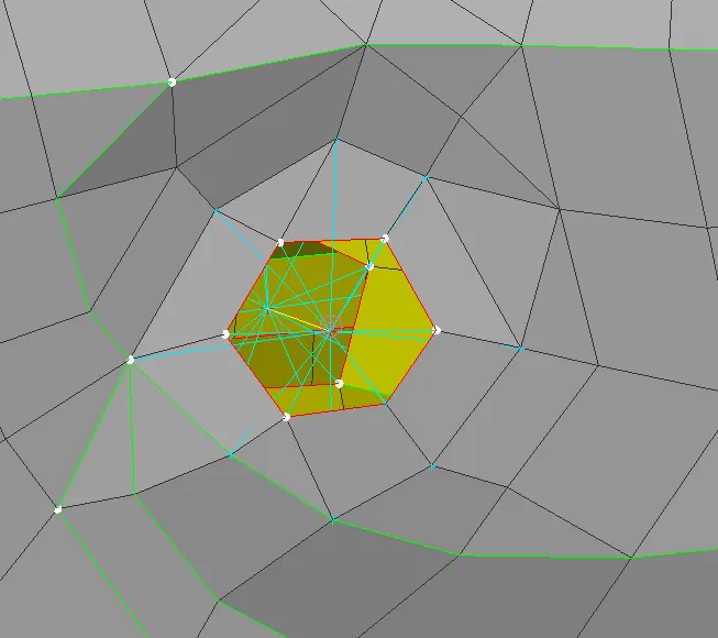
22. The holes in the component are rigidized using RBE2 elements.
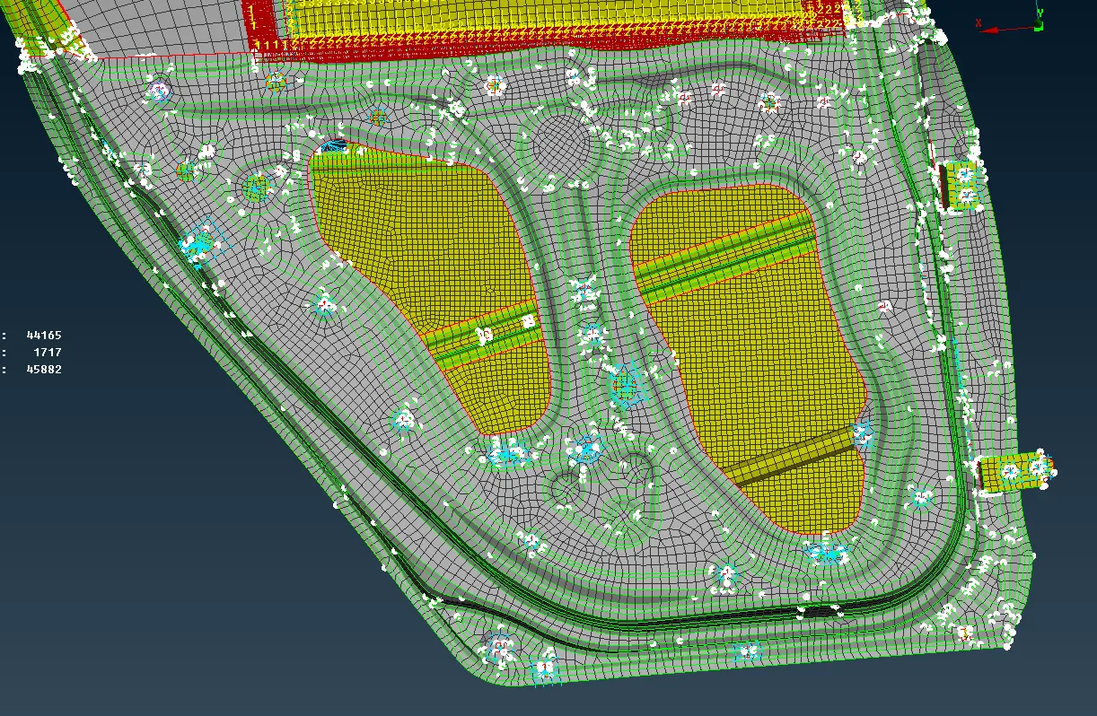
23. The two components which are having matching holes are to be connected using bolted joints as a cluster node or by the automatic method.
Outcomes:
- Understood different types of connection methods.
- Understood the methods to extract the connection data fro the cad provided
Results and conclusions:
- The given FE model is connected using different types of connections.