Modelling of an Automotive suspension assembly by using ANSA
Objective:
- To perform the surface mesh using trias and converting them to tetra mesh on the given components which are above a thickness of 5mm
- To extract the mid surfaces of the given geometry.
- To assign the thickness
- To mesh them according to the given quality criteria.
- To make necessary connections wherever required.
Procedure:
- Import the geometry.
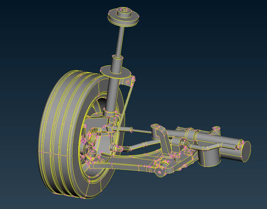
- The above picture shows the suspension system of an automobile which consists of tyre rim and steering attachment and other attachments.
- First, we have to isolate each and every part so that it is easy to model and create connections between parts it can be done by boolean operation and lock view manager.
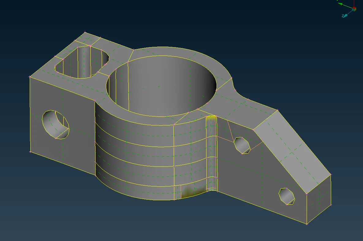
PART_1
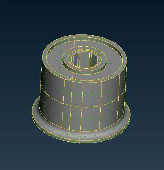
PART_2
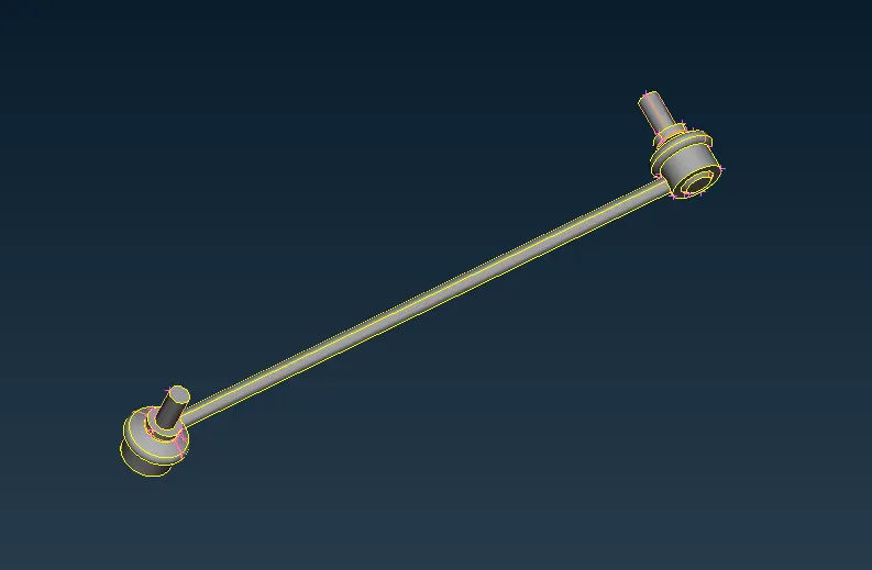
PART_3
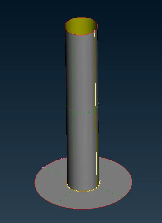
PART_4
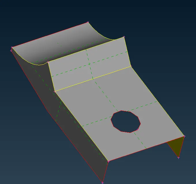
PART_5
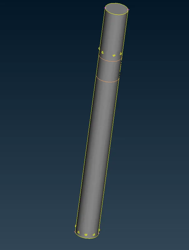
PART_6
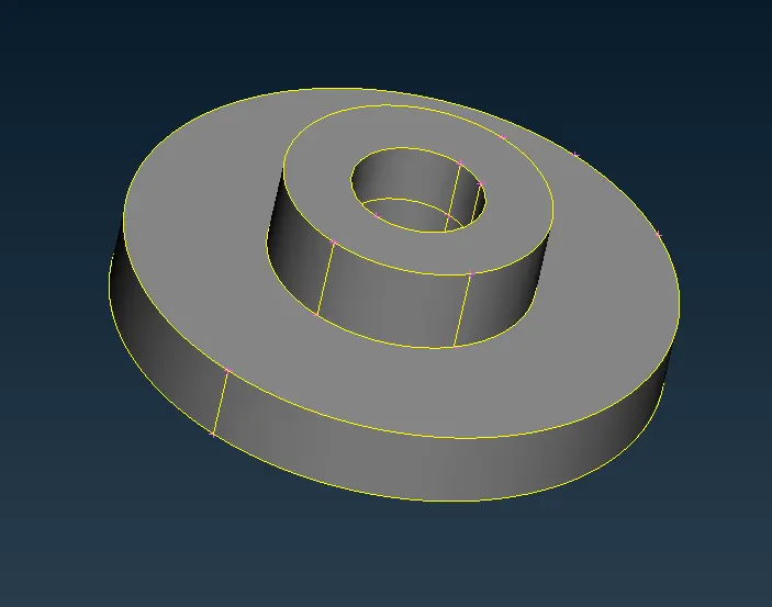
PART_7
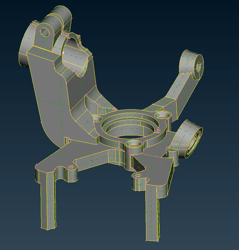
PART_8
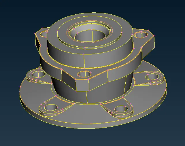
PART_9
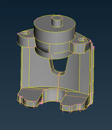
PART_10
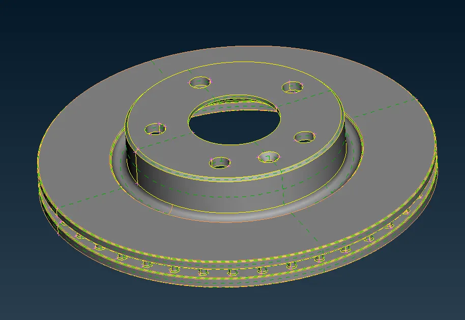
PART_11
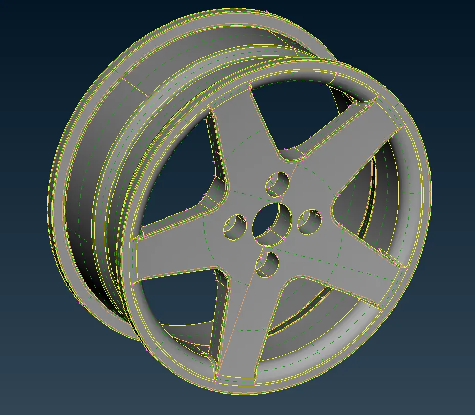 .
.
PART_12

PART_13
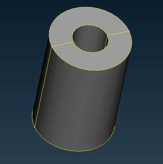
PART_14
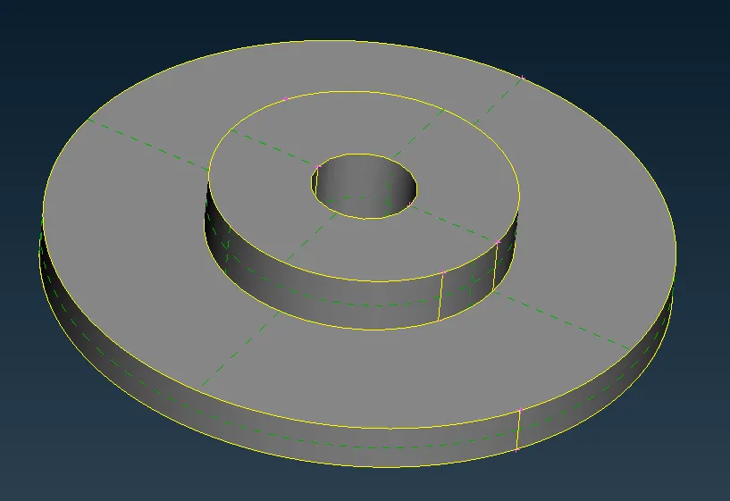
PART_15
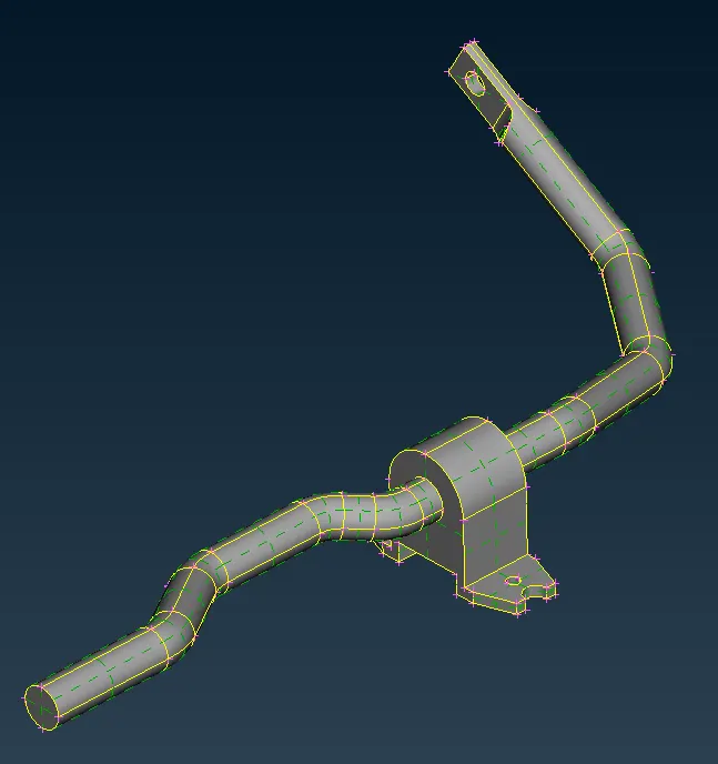
PART_16

PART_17
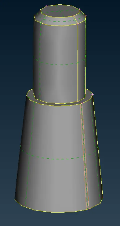
PART_18
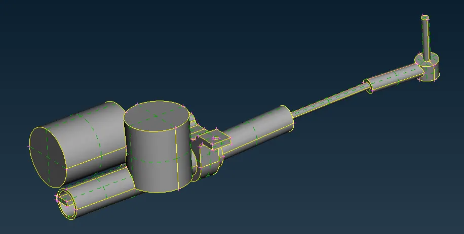
PART_ 19
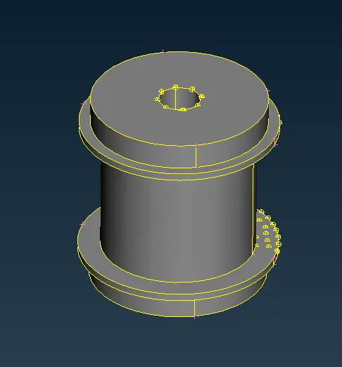
PART_20
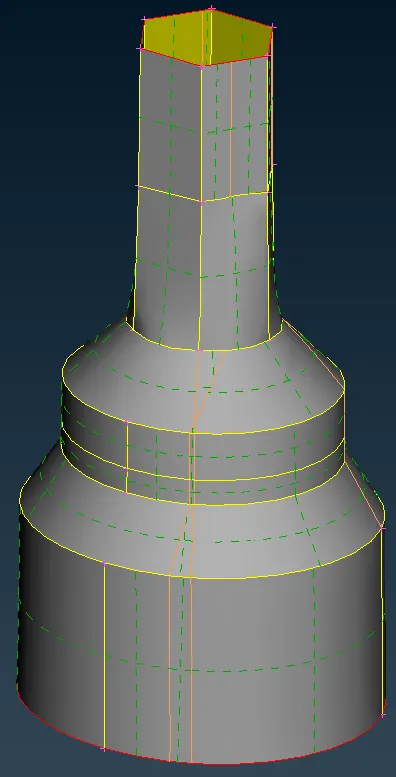
PART_21
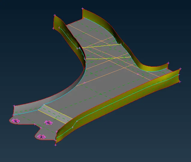
PART_22
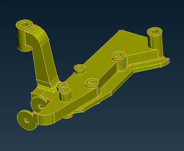
PART_23
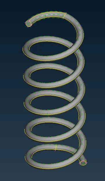
PART_24
- After isolating all the parts measure the thickness of the parts and mesh according i.e., components above 5mm are meshed using volume mesh and below 5mm are meshed using 2D shell mesh.
- In the above parts, parts_4,5,21 & 22 are having a thickness of below 5mm so we have to mesh them using quad elements.
- For the parts 4,5,21&22, we have to extract the mid surface using the faces offset option and assigning the PID and thickness for the components.
- After extracting mid surface geometry check is to be performed and errors in the geometry are auto fixed or manually fixed and assign PID.
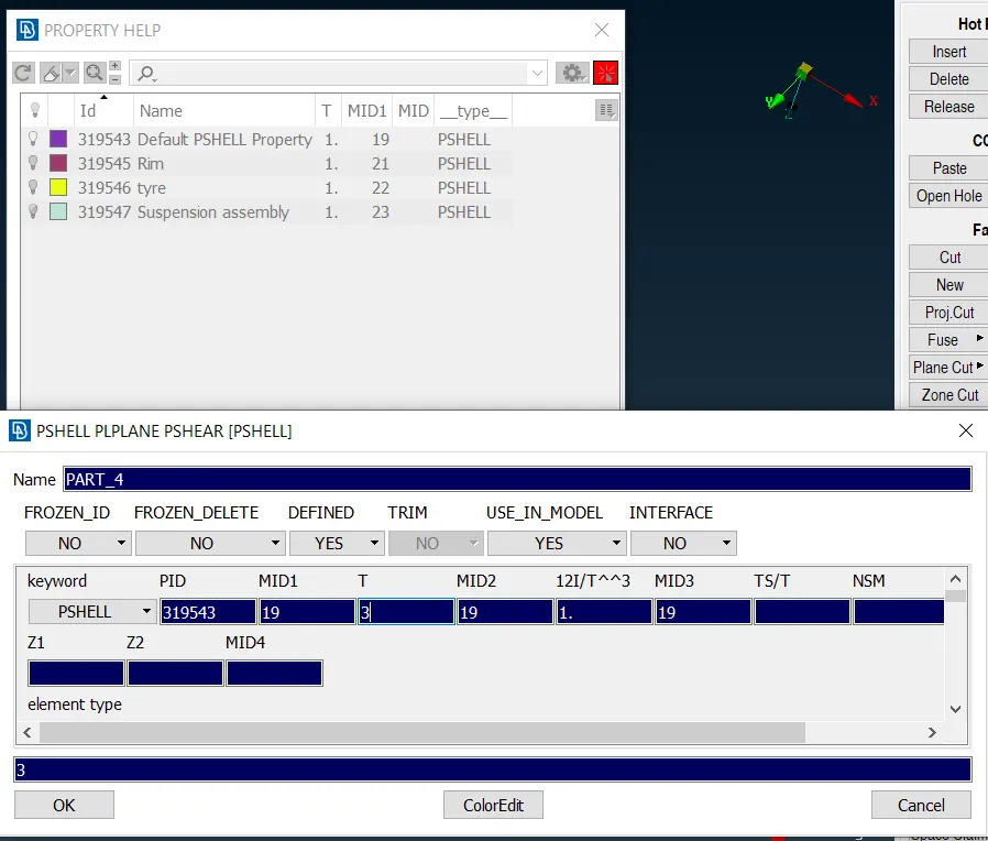
- Now set the component to target element length and give meshing parameter and quality criteria for mesh quality.
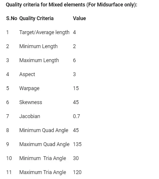
- Now mesh the components by surface by surface and check for quality and remove as many possible numbers of trias using the hybrid split option.
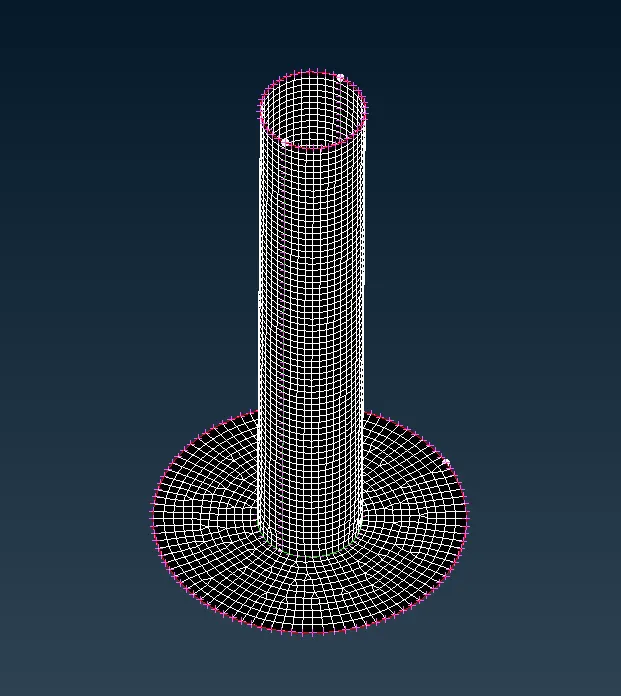
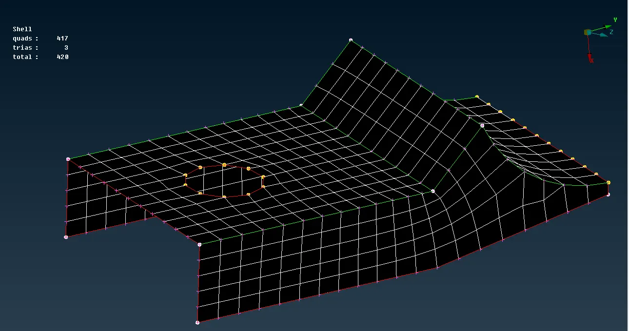
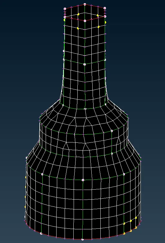
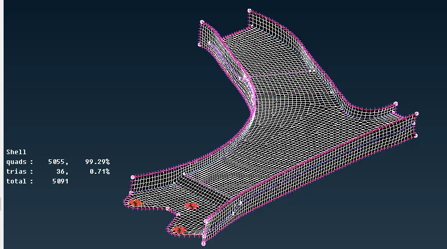
- Now surface mesh the remaining components using trias and ortho trias and define the closed volume and mesh the volume using tetra elements.
- For all the components perform topology clean up and set the components to target element length and give meshing parameters and quality parameters for trias.
- In part_1 we have the geometry which is failing for minimum length as shown below.
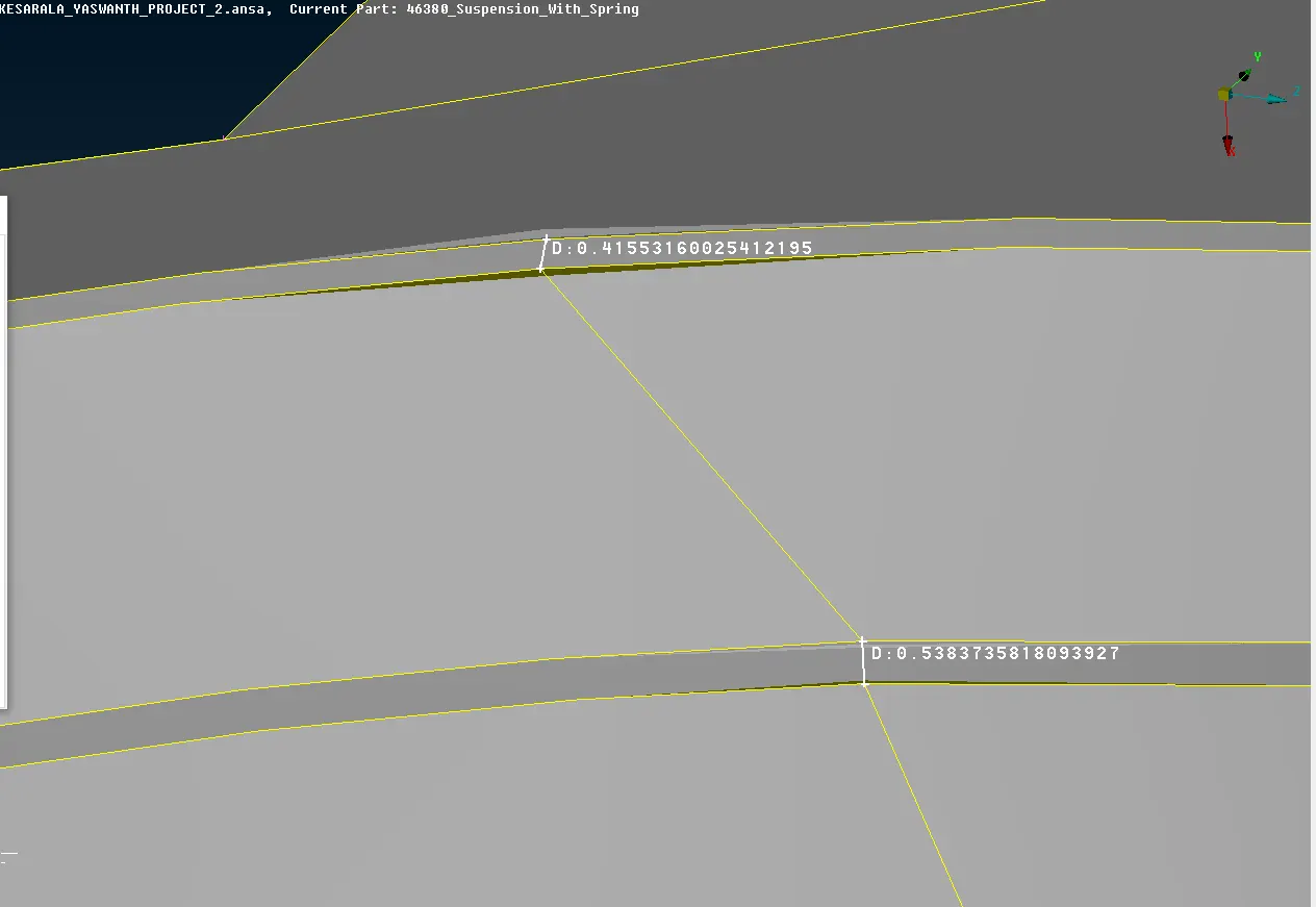
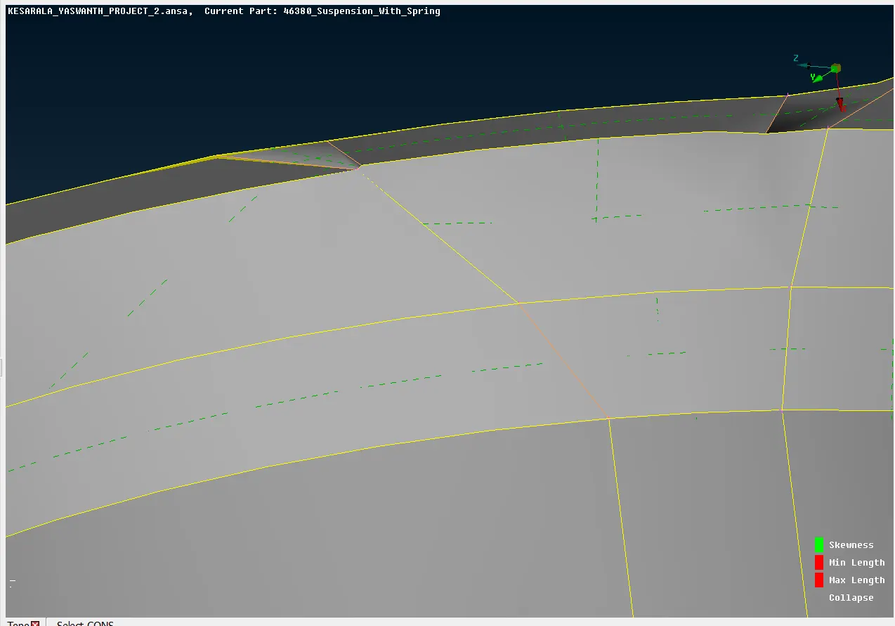
- So, we have to delete that surface and make it as single continuous surface as below.
- Now check the geometry errors using geometry check manager.
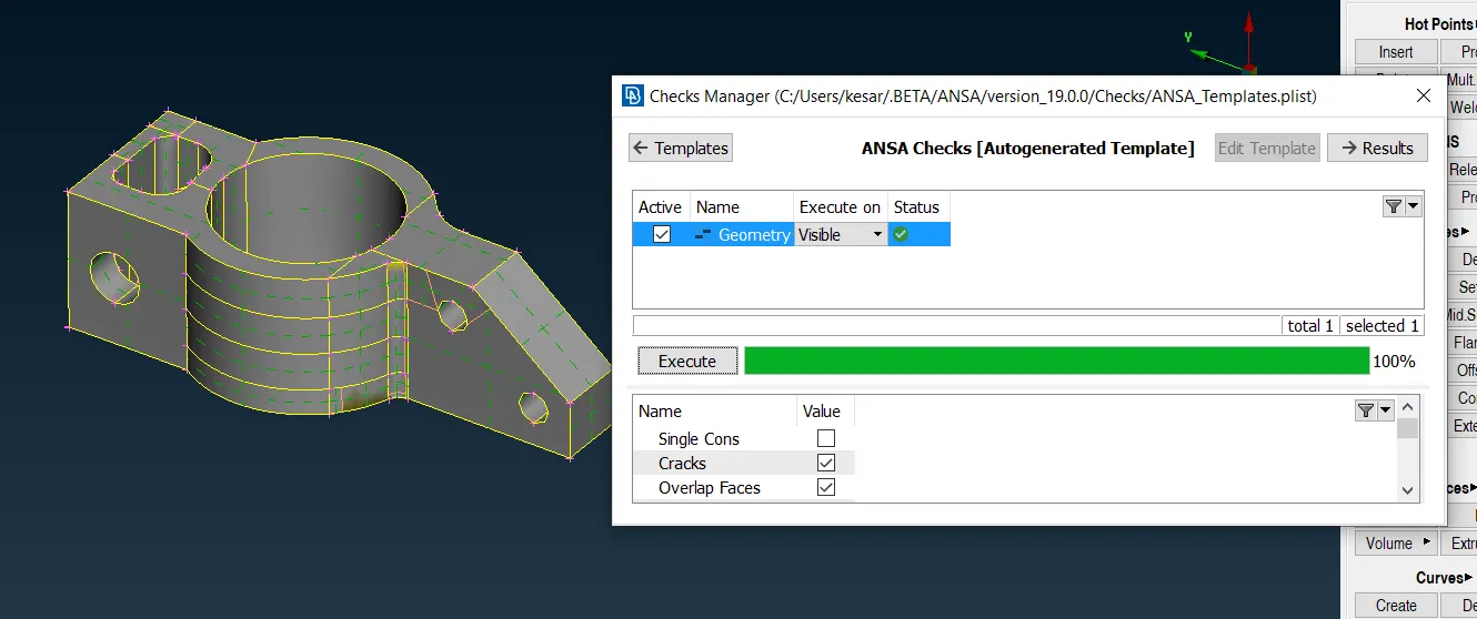
- If any geometric errors are found fix them manually or use auto-fix to clear the errors.
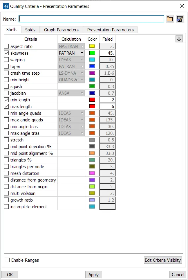
- Now insert meshing parameters and quality parameters for all the components.

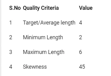
Quality and mesh parameter for tyre and rim Quality and mesh parameter for all other components
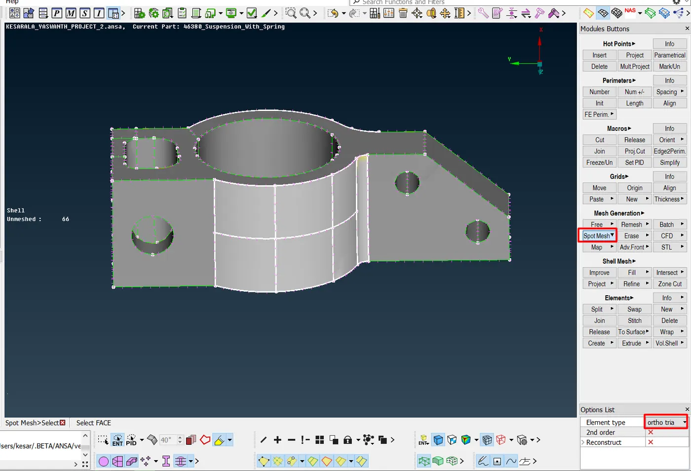
- Mesh the curved surfaces using ortho trias and flat surfaces using regular trias.
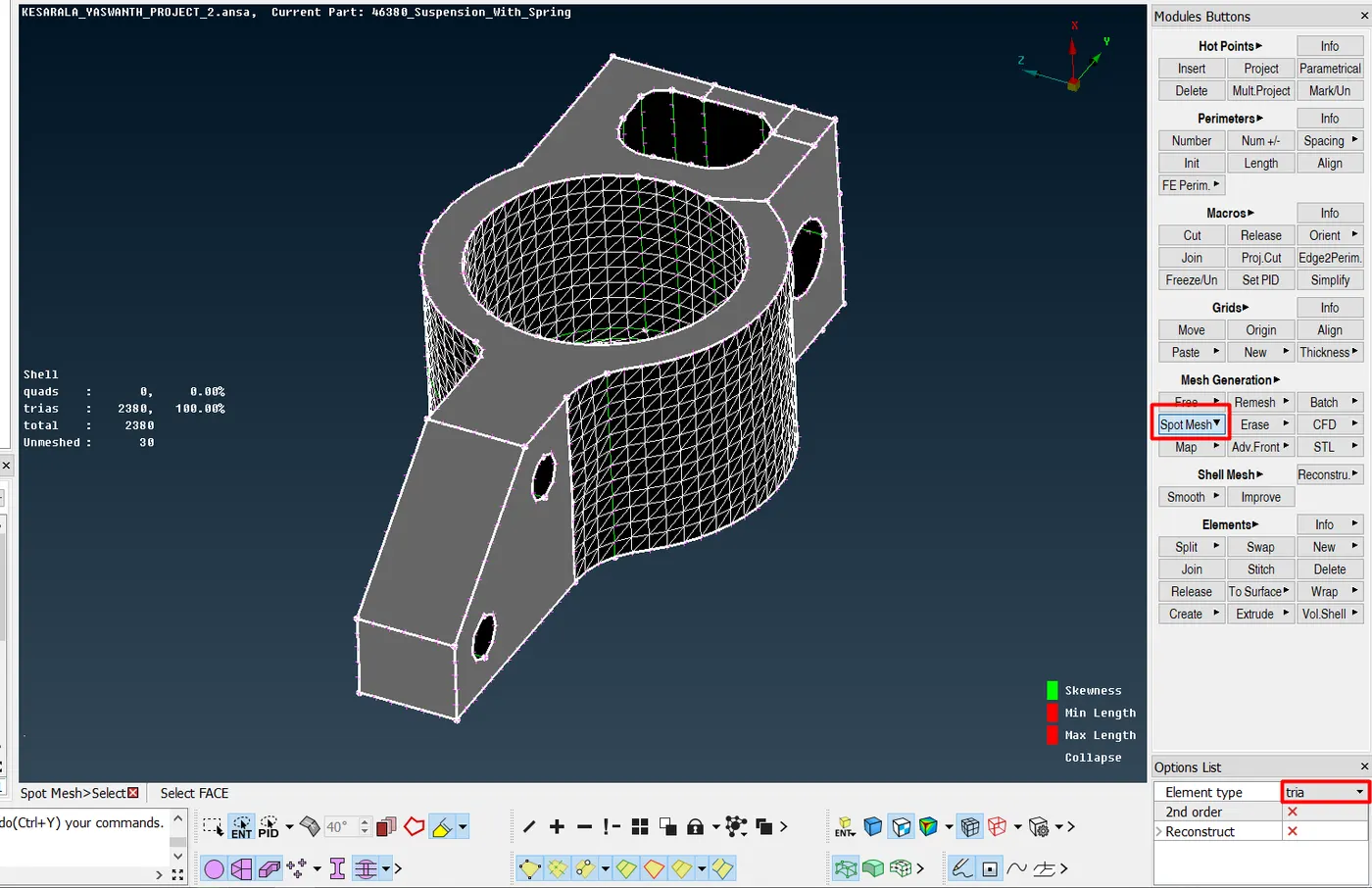
- Repeat the same procedure for all the remaining parts and surface mesh all the components as below.
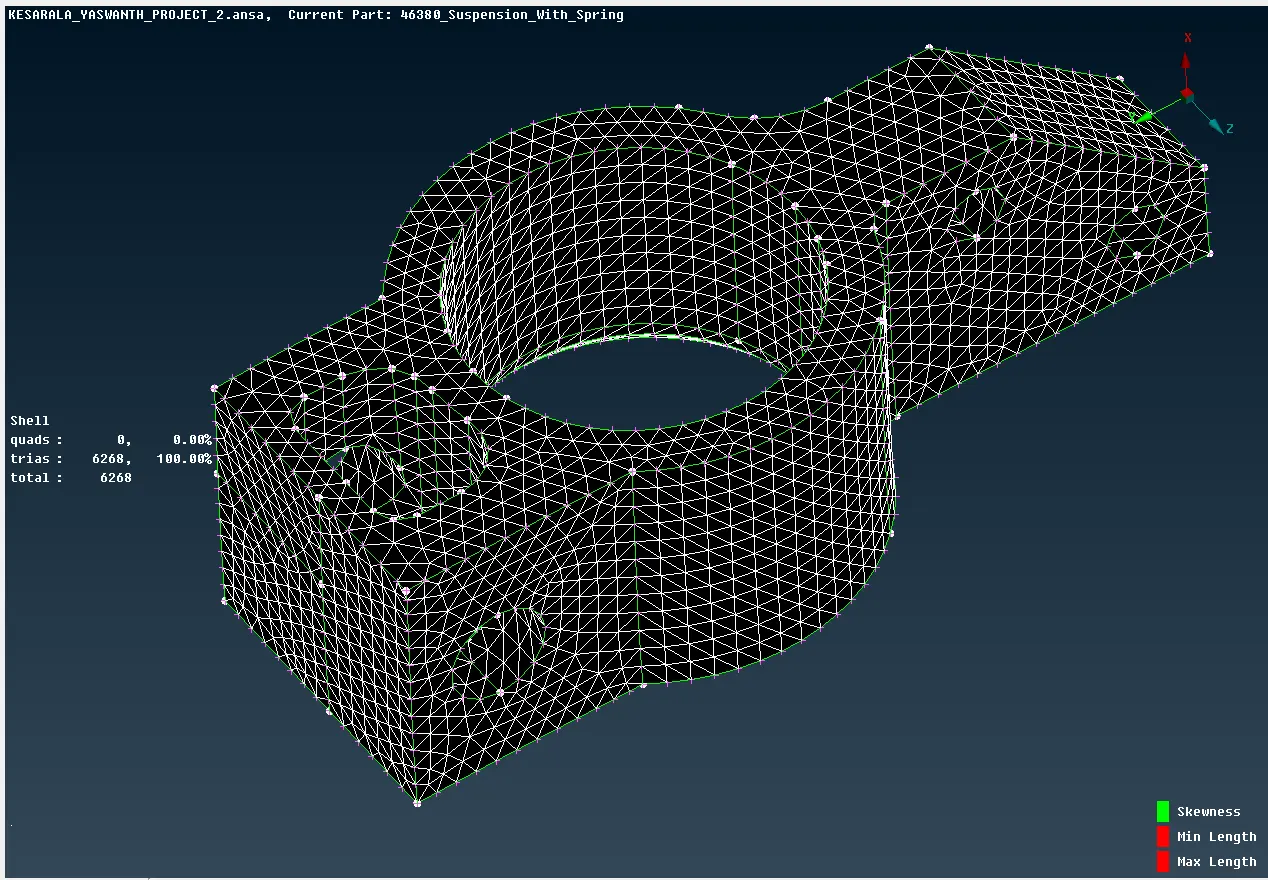
PART_1 SURFACE MESH
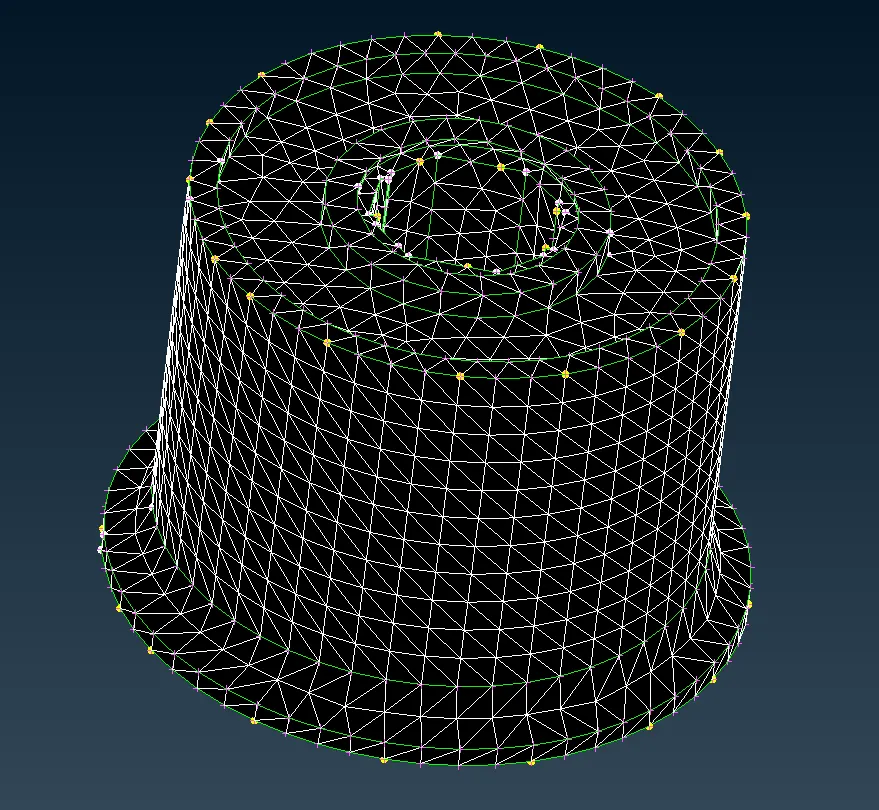
PART_2 SURFACE MESH
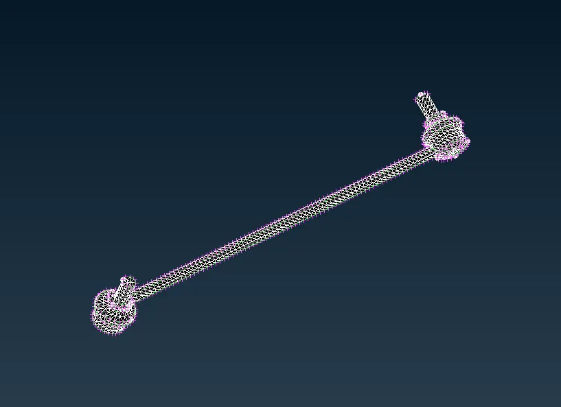
PART_3 SURFACE MESH
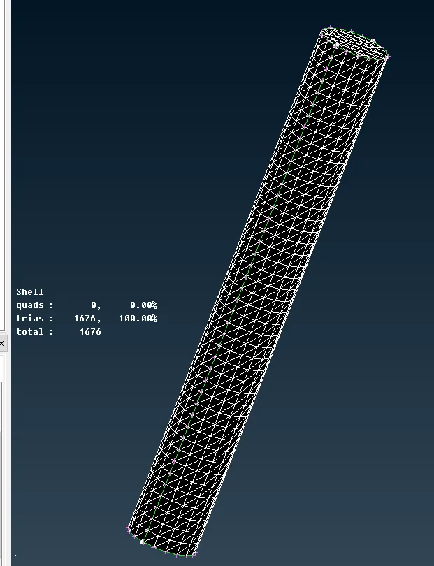
PART_6 SURFACE MESH
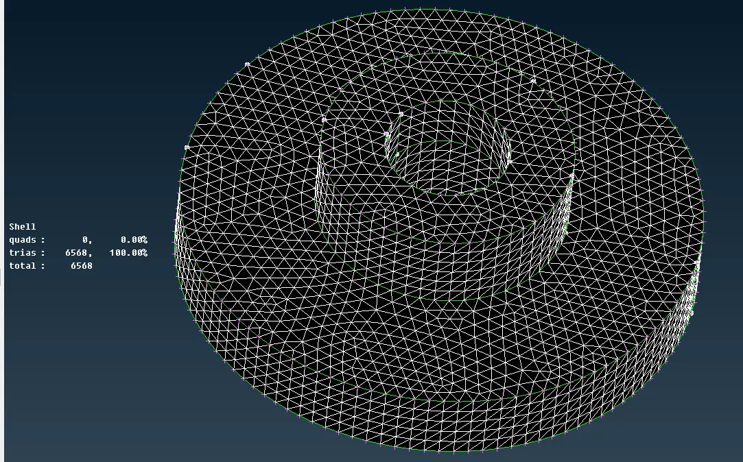
PART_7 SURFACE MESH
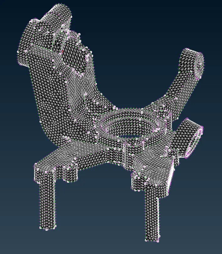
PART_8 SURFACE MESH
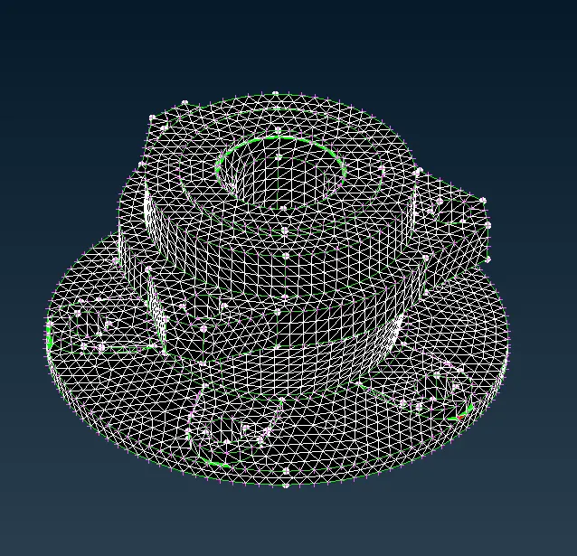
PART_9 SURFACE MESH
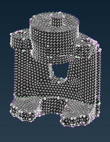
PART_10 SURFACE MESH
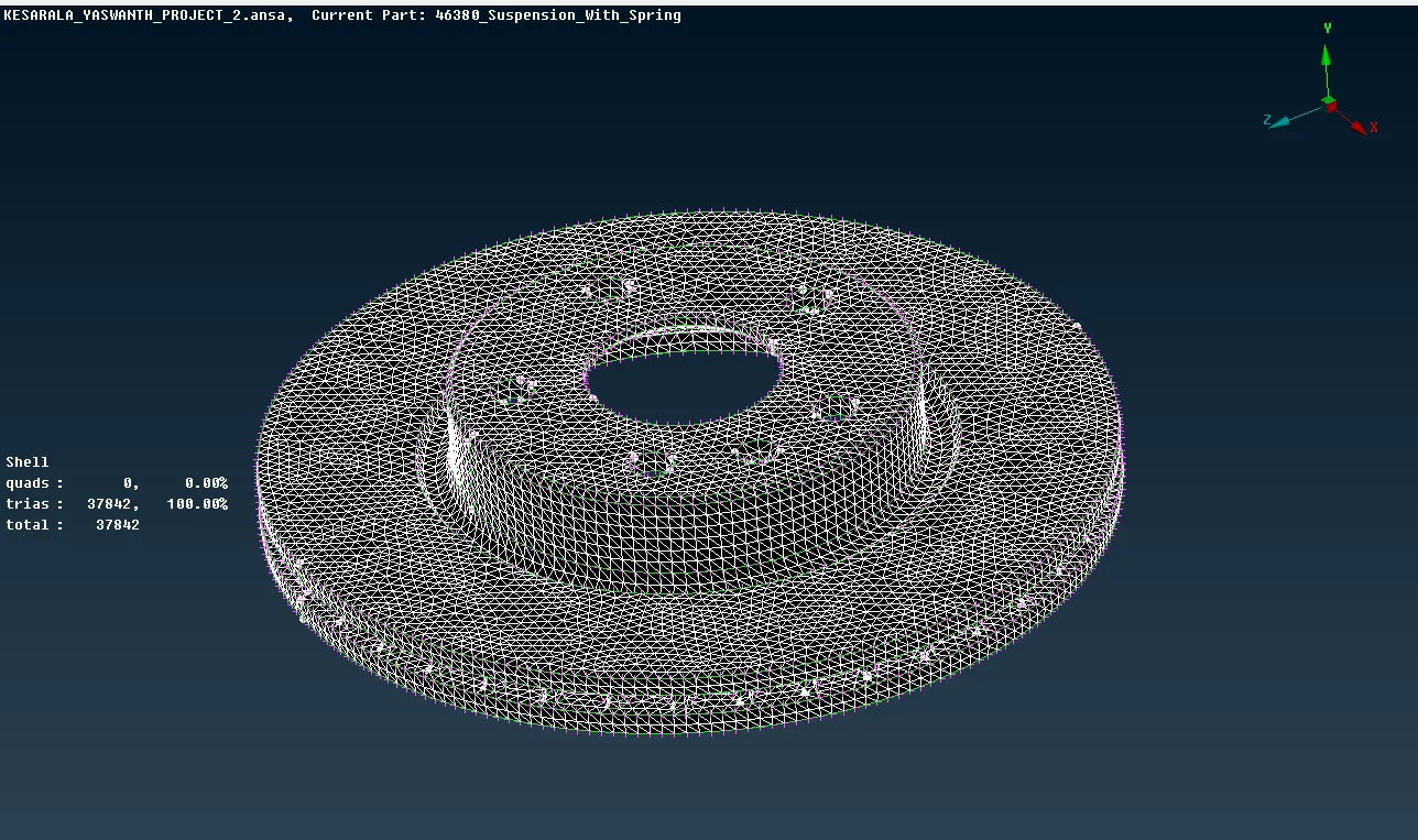
PART_11 SURFACE MESH
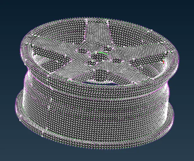
PART_12 SURFACE MESH
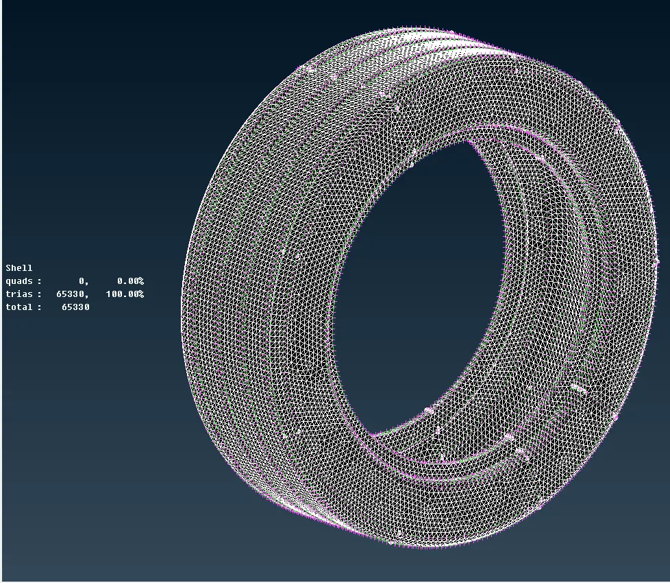
PART_13 SURFACE MESH
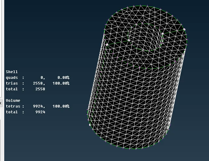
PART_14 SURFACE MESH
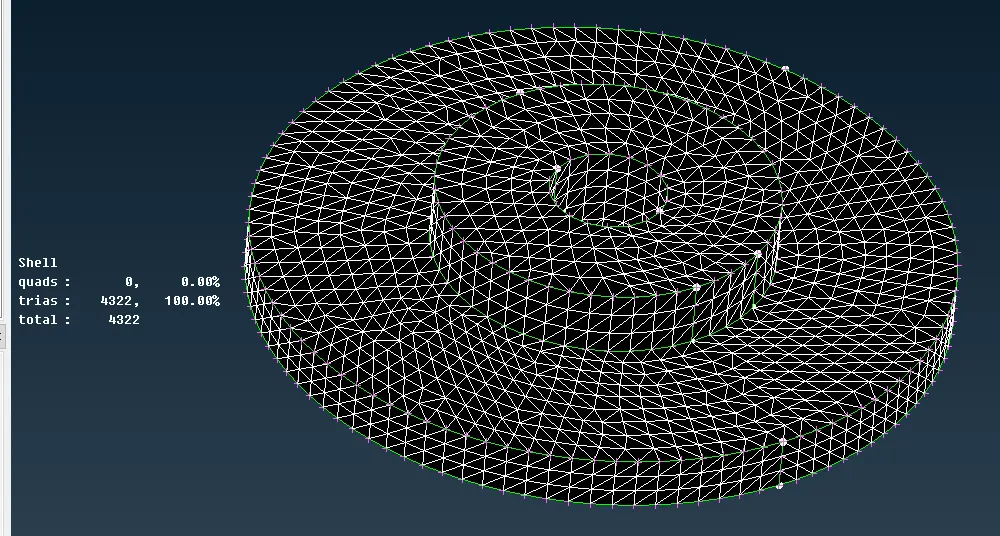
PART_15 SURFACE MESH
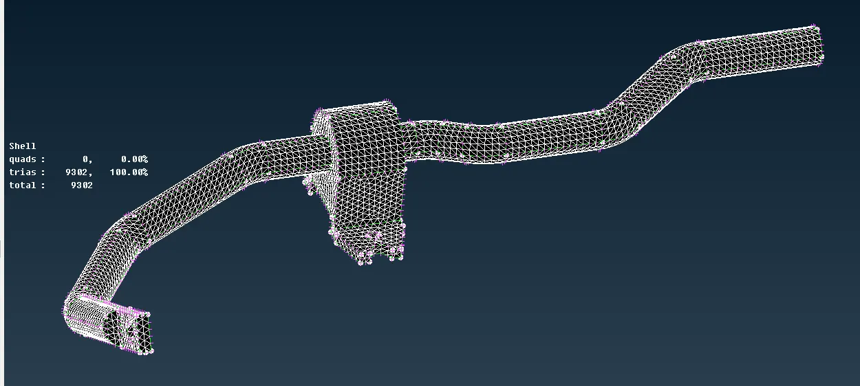
PART_16 SURFACE MESH
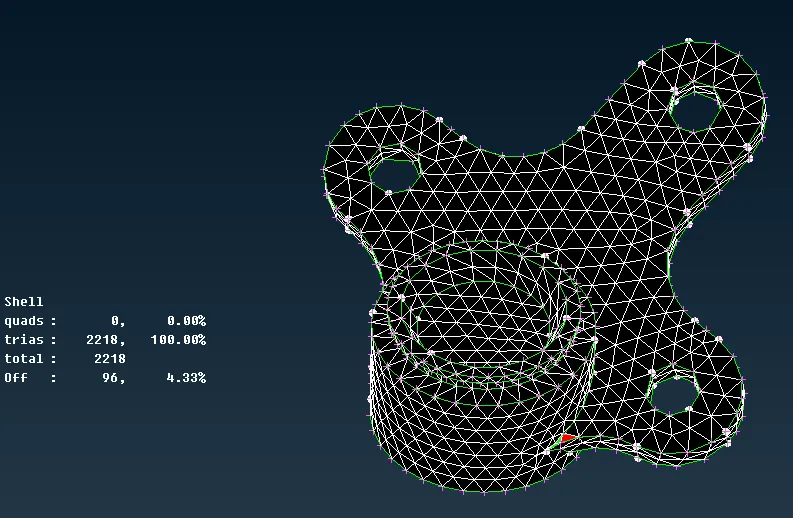
PART_17 SURFACE MESH
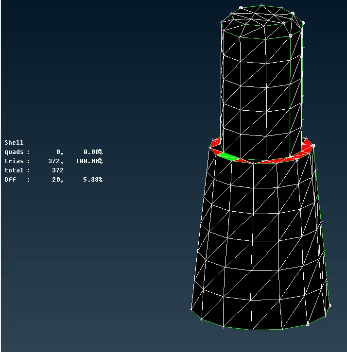
PART_18 SURFACE MESH
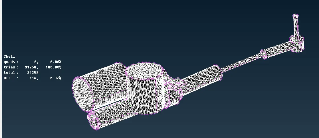
PART_19 SURFACE MESH
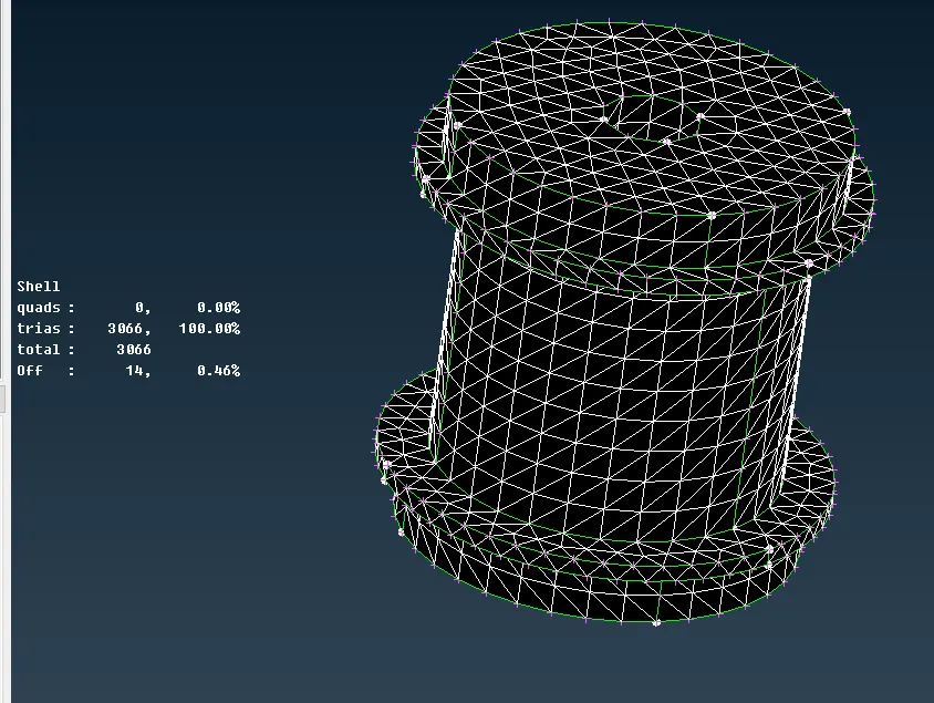
PART_20 SURFACE MESH
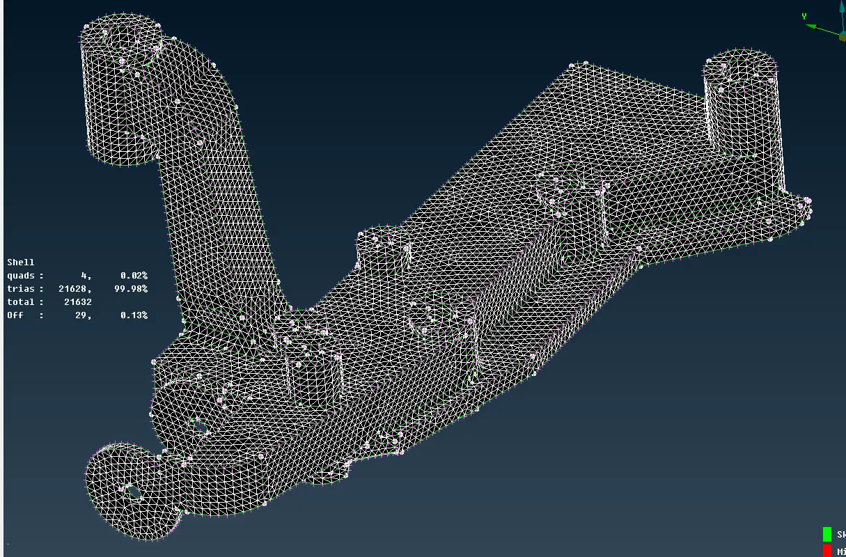
PART_23 SURFACE MESH
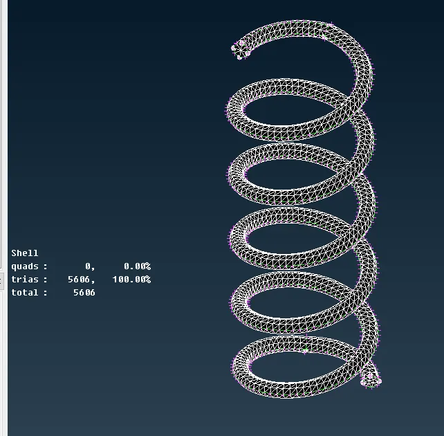
PART_24 SURFACE MESH
- After surface meshing using the volume menu define option define the volume for the surface meshed components make sure that the volume defined is a must and should be closed.
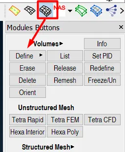
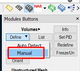
- Select the closed volume and define it and go to list under volumes and mesh the defined closed volume using tetra mesh algorithms and check the tetra elements for tet collapse.
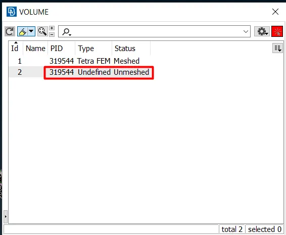
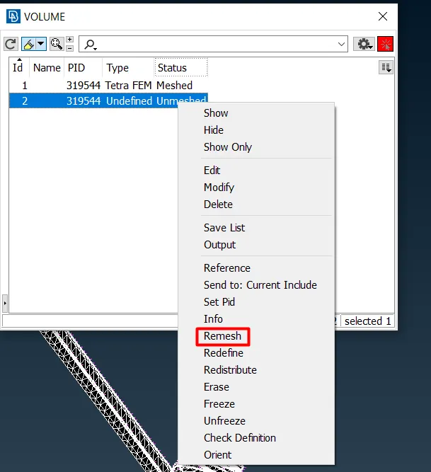
- Repeat the same procedure for all the components and mesh them using volume mesh as below.
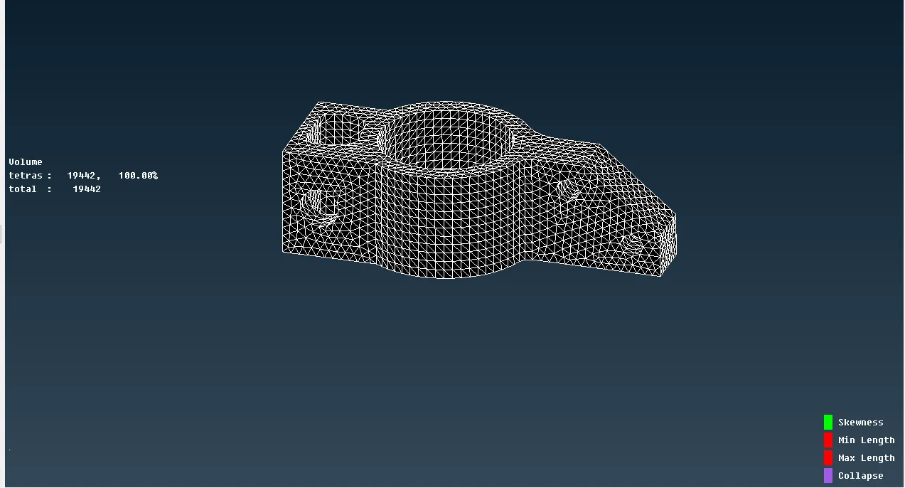
PART_1 TERA MESH
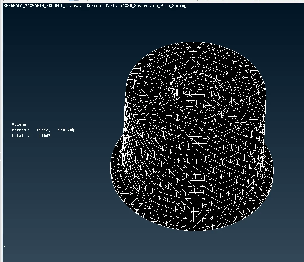
PART_2 TERA MESH
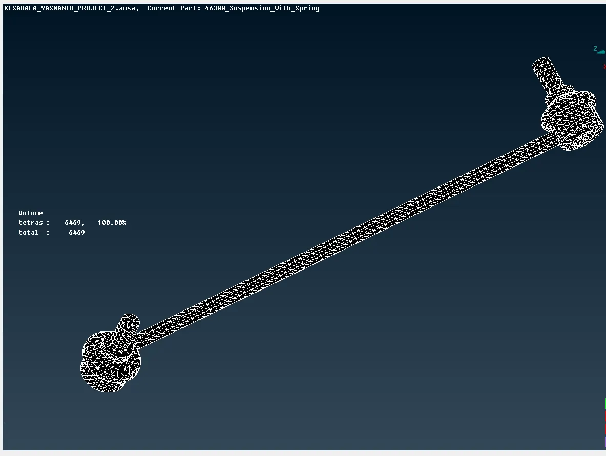
PART_3 TERA MESH
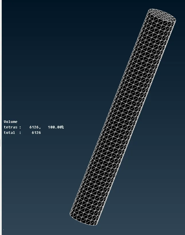
PART_6 TERA MESH
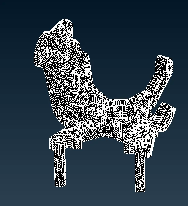
PART_7 TERA MESH
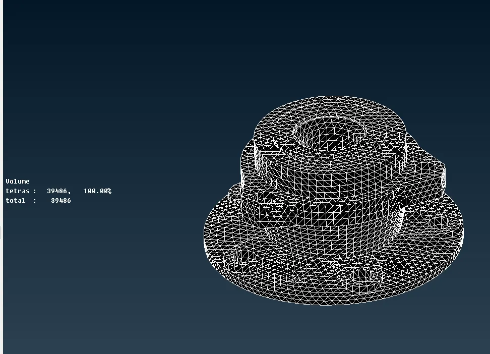
PART_8 TERA MESH
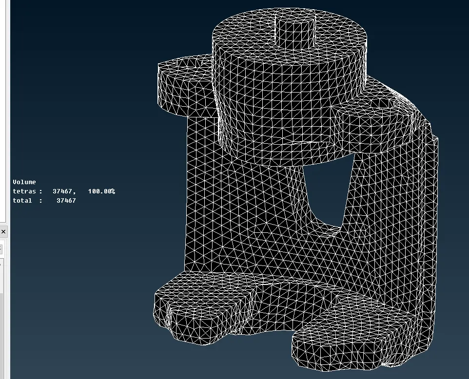
PART_9 TERA MESH
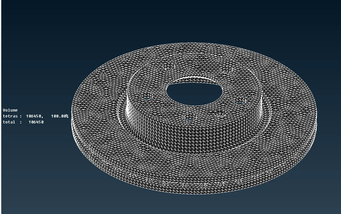
PART_10 TERA MESH
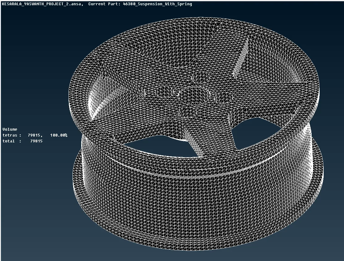
PART_11 TERA MESH
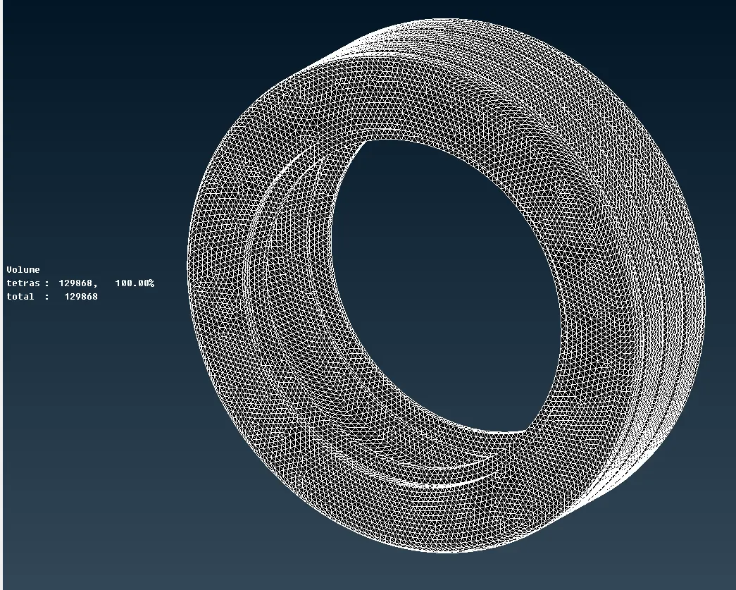
PART_12 TERA MESH
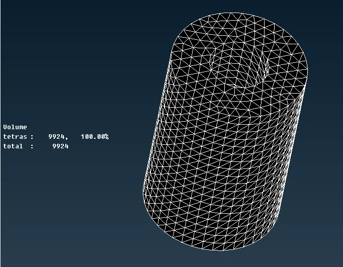
PART_13 TERA MESH
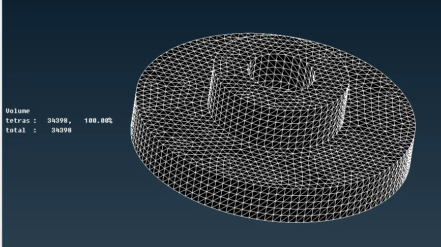
PART_14 TERA MESH
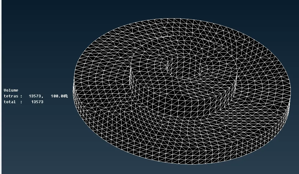
PART_15 TERA MESH
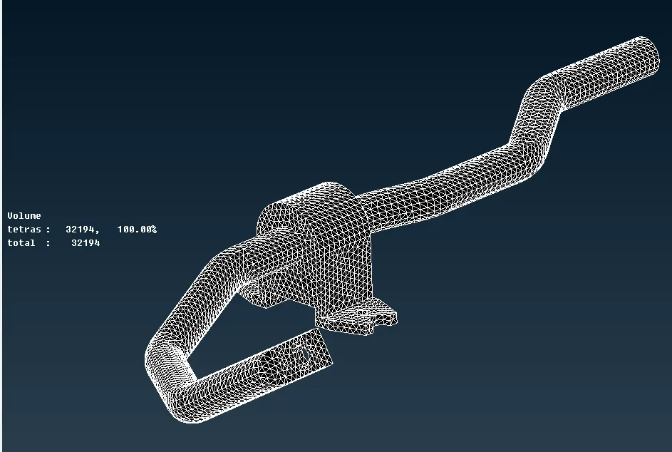
PART_16 TERA MESH
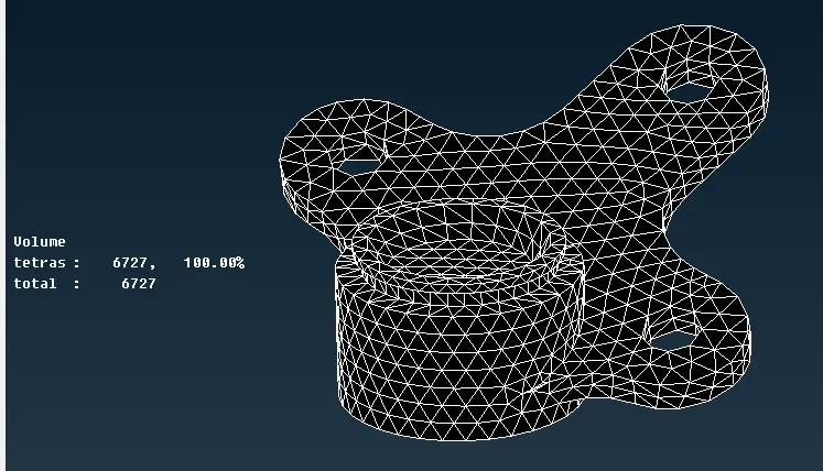
PART_17 TERA MESH
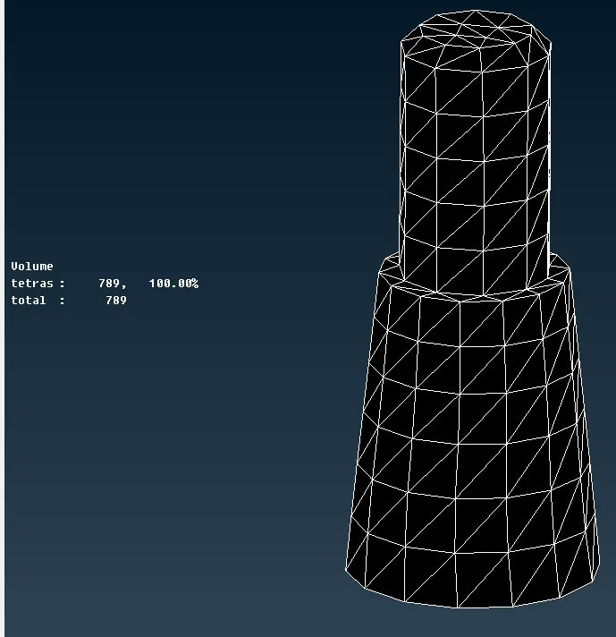
PART_18 TERA MESH
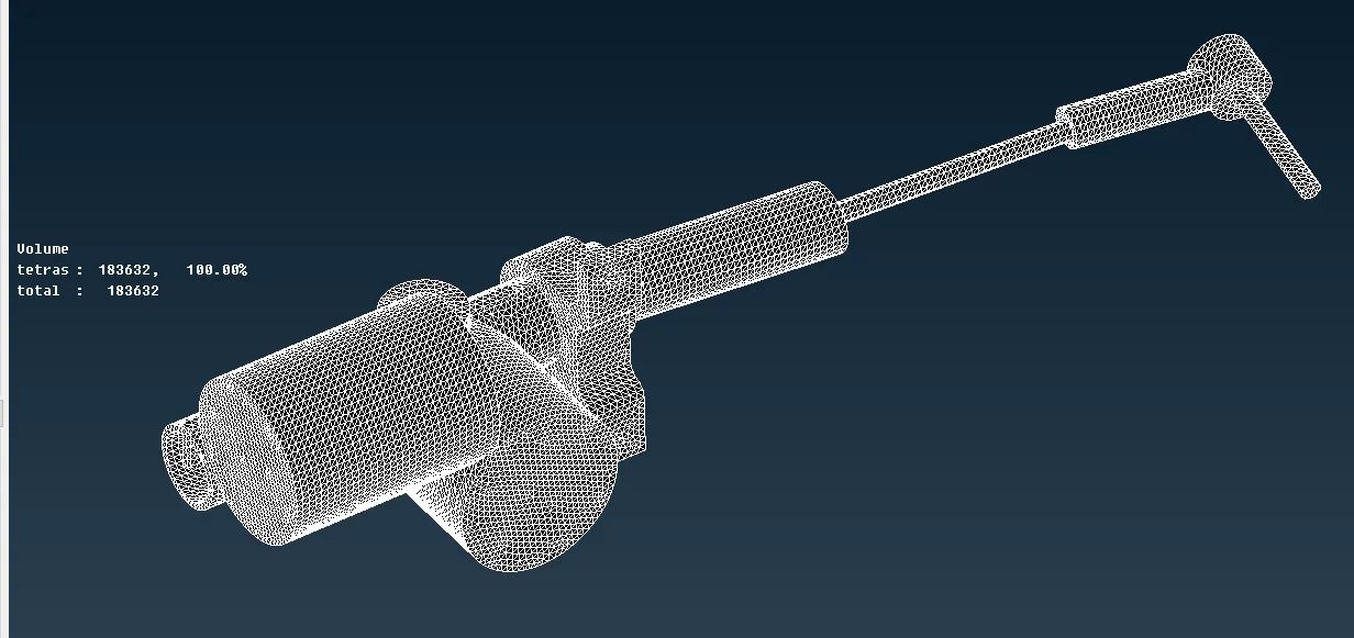
PART_19 TERA MESH
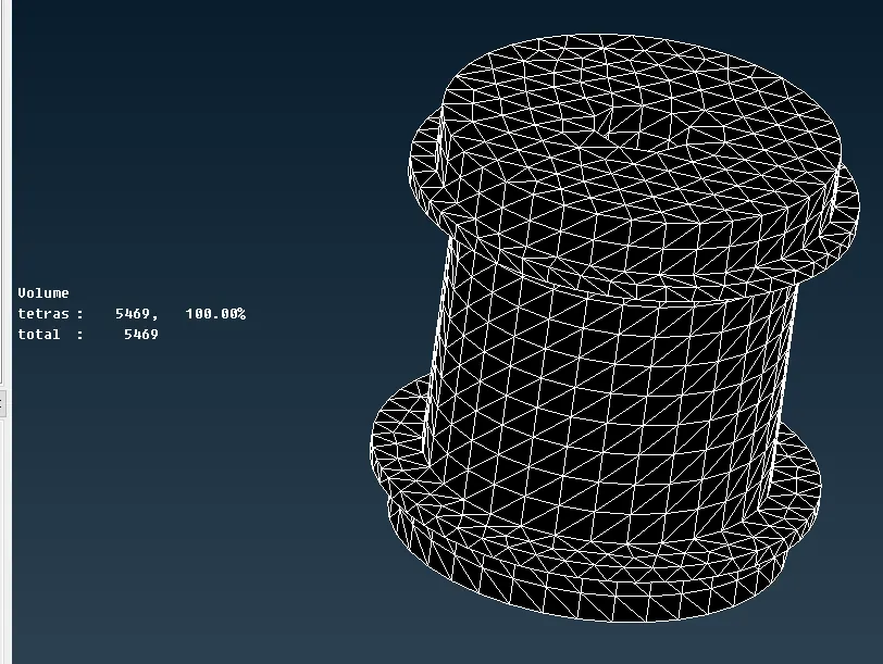
PART_20 TERA MESH
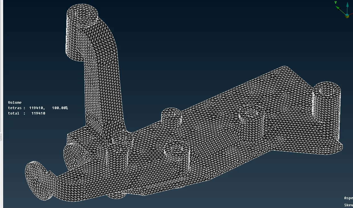
PART_23 TERA MESH
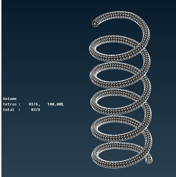
PART_24 TERA MESH
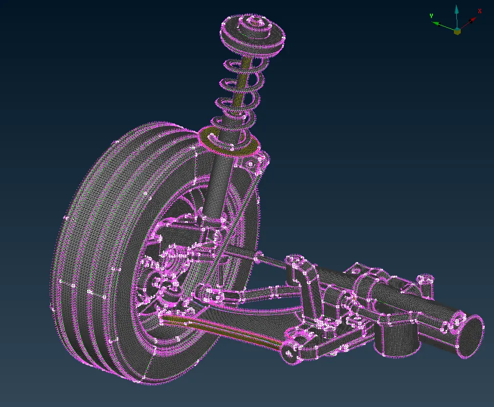
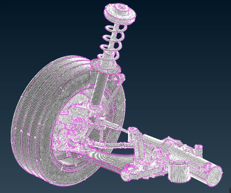
- After meshing all the components using shell and tetras turn on the drag shells as solids option.
- Now make necessary connections require as below.
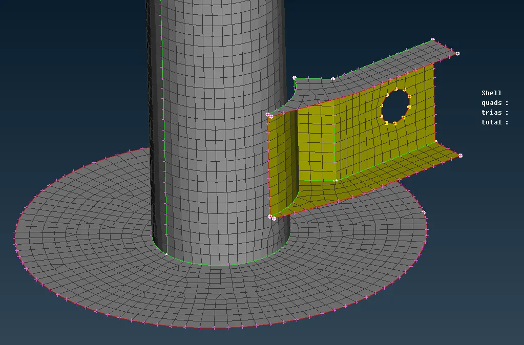
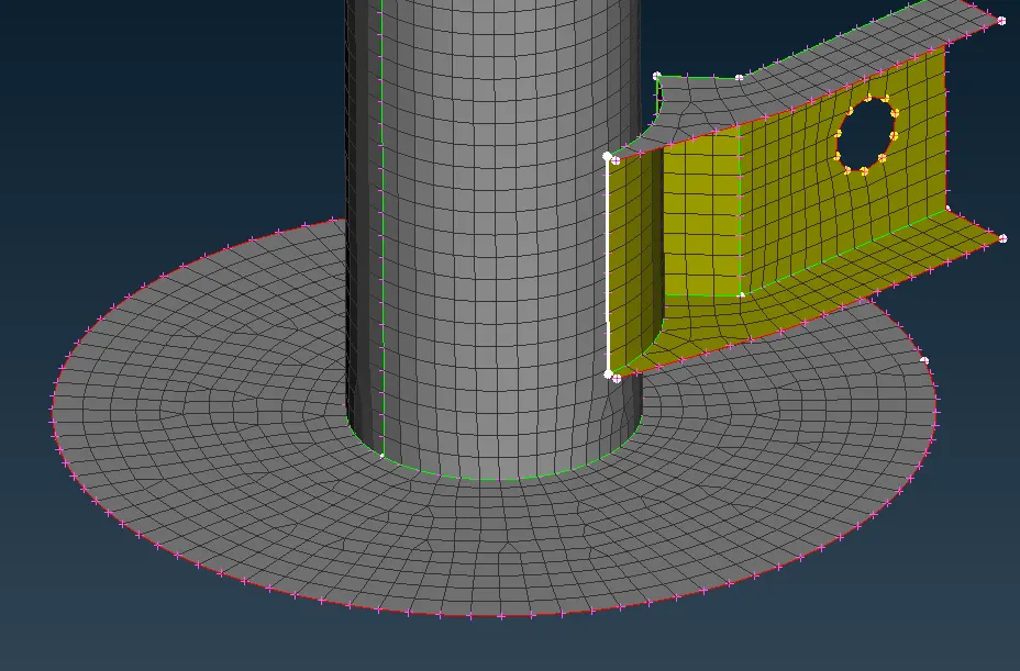
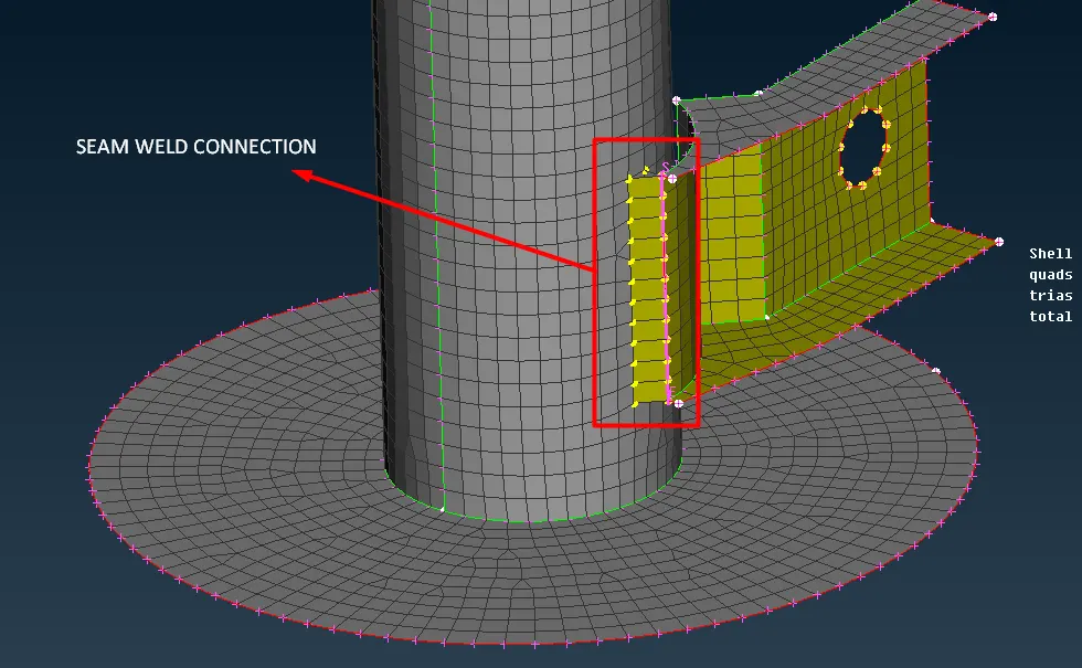
- In the above picture, the parts_4&5 the mesh flow of the parts are parallel so the components are connected using seam weld with overlap shells.
- Go to curves cons2curves option and convert the feature line to the curve.
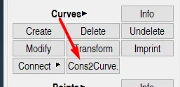
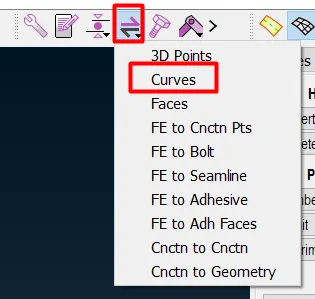
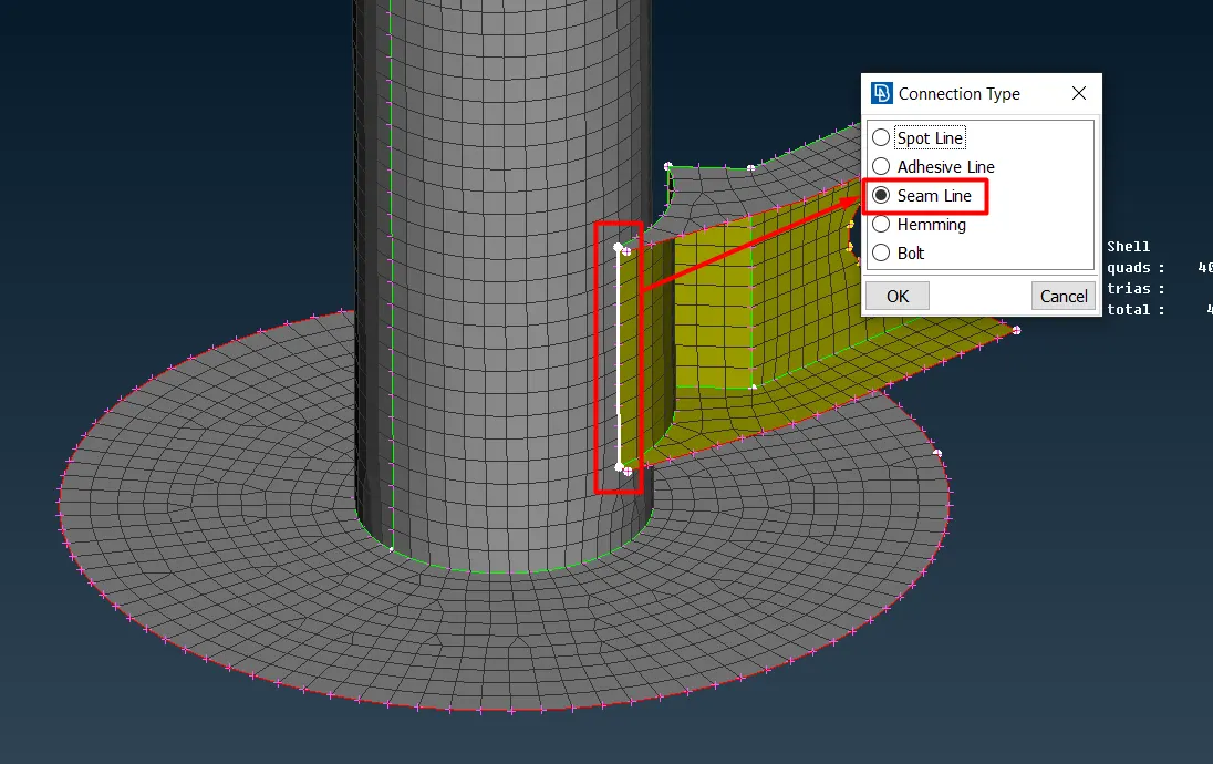
- Now go to the connection selection assistant and assign the parts and weld thickness and weld PID for the seam weld and realize the welding.
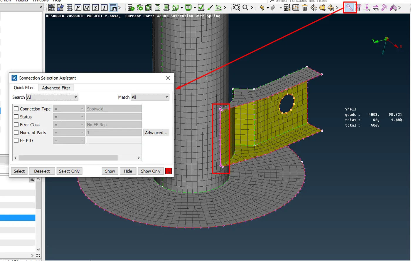
- Assign the p1 and p2 and realize the weld as below.
- In the above picture, the two components are to be bolted to each the bolt connection can be created in two ways i.e., with 2d representation or many node RBE2 with one two-node RBE2 as bolt stem as below.
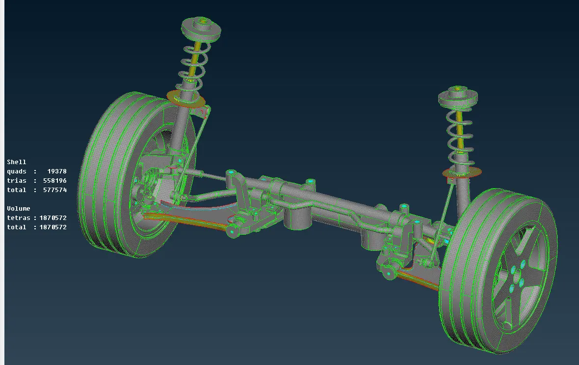
- Connect all the components with each other using necessary connections wherever required and rigidize the system.
TWO COMPONENTS CONNECTED USING TWO-NODE RBE2 ELEMENTS
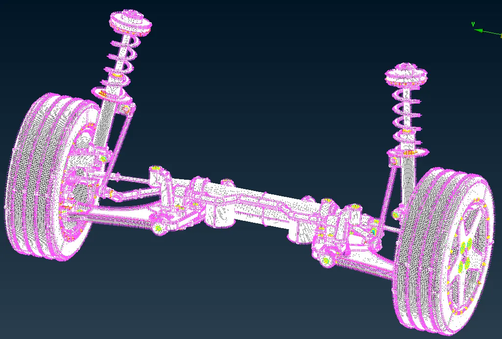
- After creating all the necessary connections mirror the entire suspension system to for a complete suspension with two wheels as below using the translate option.
Outcomes:
- Different methods of extracting mid are understood.
- FE modeling of the component is understood.
- Different volume meshing algorithms are understood
- Different types of connections and procedure to make a necessary connection are understood
Results and conclusion:
- The mid surface for the given components is extracted successfully.
- All the components have meshed according to the given quality criteria.
- The thickness is assigned for the given component successfully.
- All the components having a thickness of above 5mm are meshed using tetra volume mesh successfully.
- All the required connections are created successfully.