Week 7-Long Piston With Cam
AIM:
- To perform the transient analysis on a piston and cam mechanism model with frictionless contact and frictional contact with a coefficient of friction of 0.1 and 0.2 and to compare the results obtained.
PROCEDURE:
Transient analysis: Transient structural analysis is also referenced as flexible dynamic analysis. It can be used to find out the dynamic response of a structure under the action of any general time-dependent loads. The flexible dynamic analysis is the most versatile dynamic analysis and it can use it to determine the time-varying displacements, strains, stresses, and forces in a structure as it responds to any transient loads.
CASE-1: ANALYSIS ON A PISTON CAM MECHANISM WITH FRICTIONLESS CONTACT.
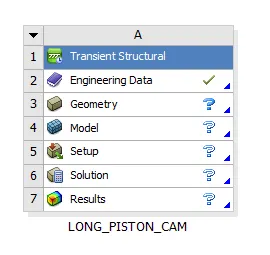
- Open ansys workbench and create a transient structural system and rename it as piston and cam mechanism.
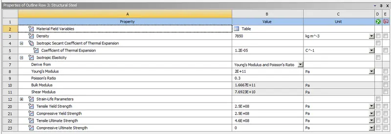
- Open engineering data and add structural steel.
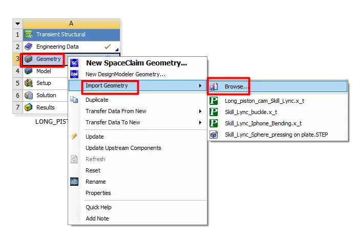
- Browse to geometry location and import the geometry.
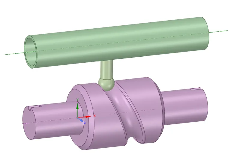
- Open Spaceclaim and check for abnormalities in the model.
- Open ansys mechanical to set up the analysis.
- Rename the geometries.
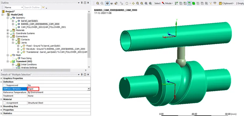
- Select the barrel and cam change the behavior to rigid.
- Now go to contacts and select both the contacts and flip the contact and target bodies and remove the unwanted selections from contacts.
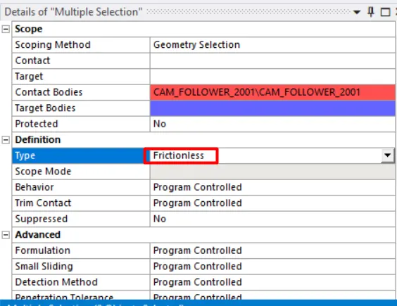
- Change the contact type to frictionless.
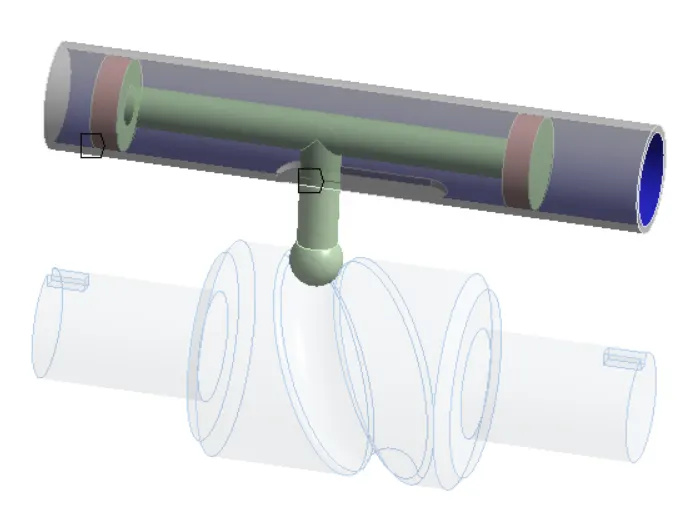
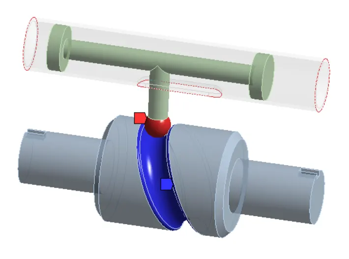
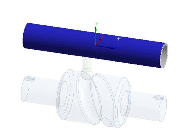
- Now create a body-ground fixed joint by selecting the face of the barrel.
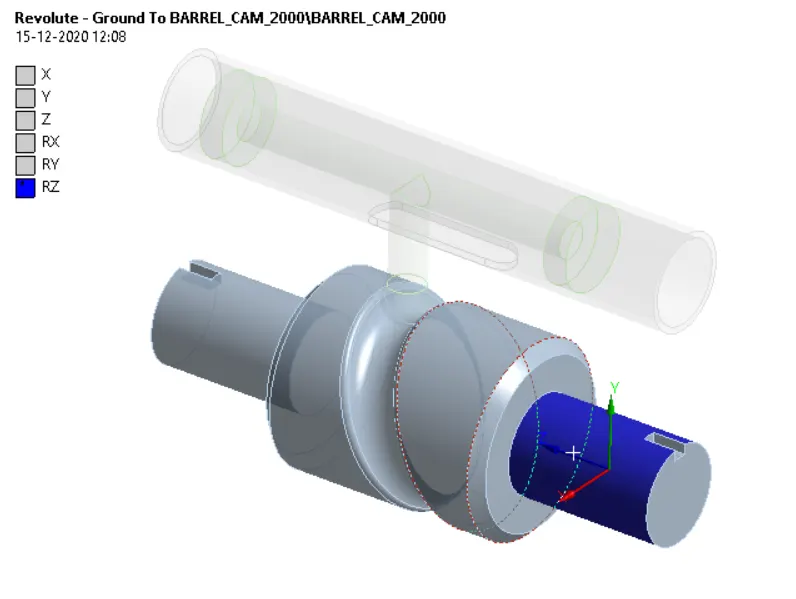
- Now create a body-ground revolute joint by selecting the face of the cam.
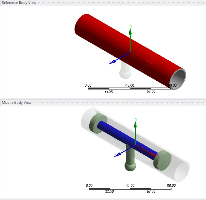
- Now create a body-body translation joint by selecting the inner surface of the piston as a mobile reference and select the outer surface of the barrel as a body.
- Now go to mesh insert sizing select the surfaces in contact and give an element size of 3mm.
- Switch off the adaptive sizing.
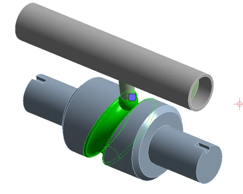
- Now generate the mesh.
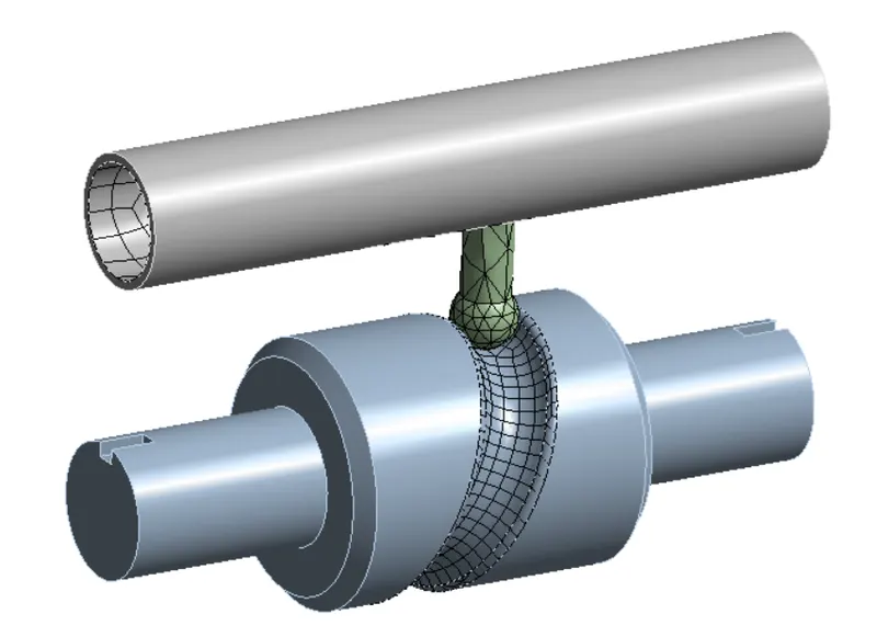
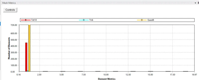
- The above graph represents mesh metrics which gives the quality and type of elements used for the analysis.
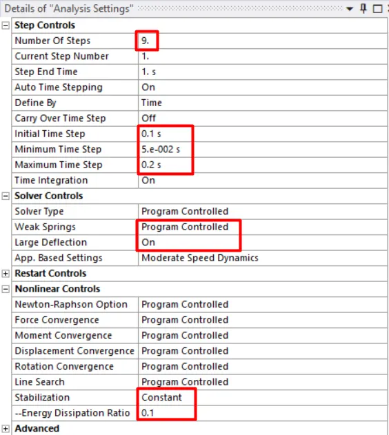
- Now go to analysis settings change the number of steps to 9.
- For step-1 change the initial time step 0.1 minimum to 5E-0002 and maximum time step to 0.2.
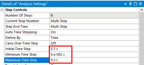
- Now select from step-2 to 9 and change the initial time step 0.1 minimum to 5E-0002 and maximum time step to 0.3.
- Change the weak springs to program-controlled and turn on the large deflection.
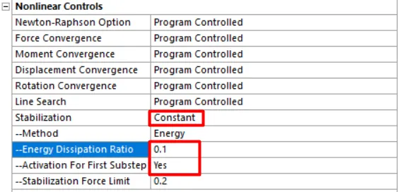
- Turn on stabilization and change the energy dissipation ratio to 0.1.
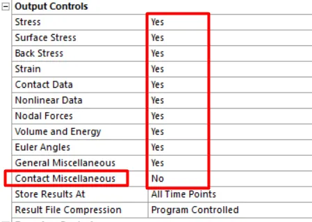
- Under output, controls change all the settings to yes except contact miscellaneous.
- Change the activation for the first substep to yes.
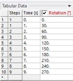
- Now apply joint load for revolute joint as rotation in tabular form.
- List the output required Equivalent Stress, Directional Deformation, and Equivalent Elastic Strain and run the simulation.
CASE-2
- Select the two contacts and change the contact type to frictional with a coefficient of friction of 0.1.
- Setup the analysis as case-1 and simulate the model.
CASE-3
- Select the two contacts and change the contact type to frictional with a coefficient of friction of 0.2.
- Setup the analysis as case-1 and simulate the model.
RESULTS:
CASE-1: FRICTIONLESS CONTACT.
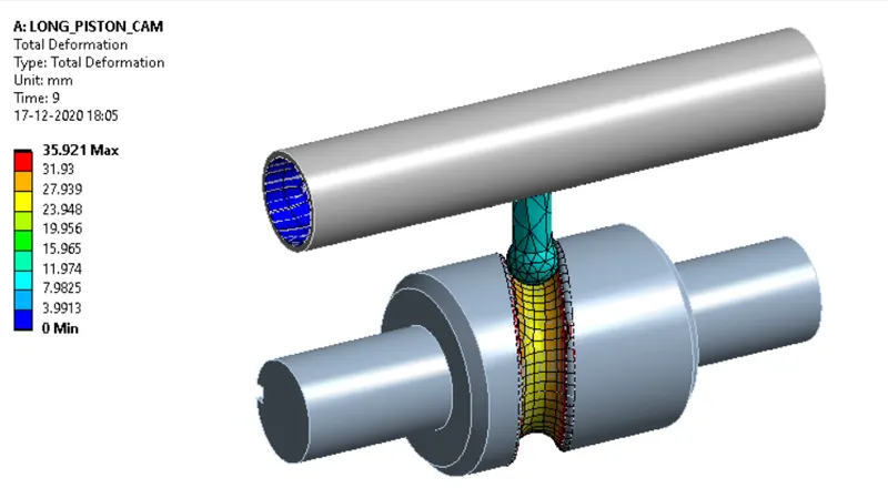
TOTAL DEFORMATION:
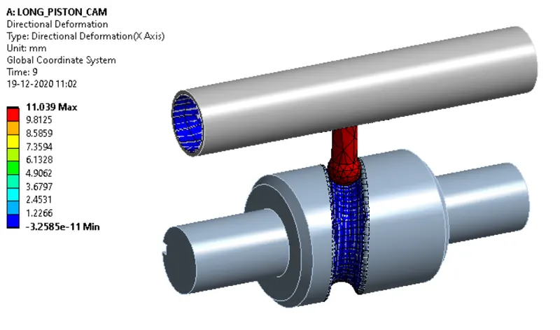
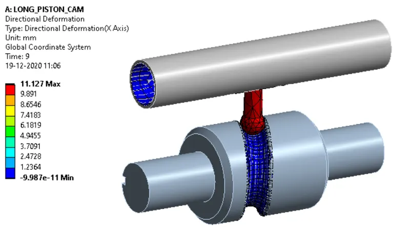
DIRECTIONAL DEFORMATION:
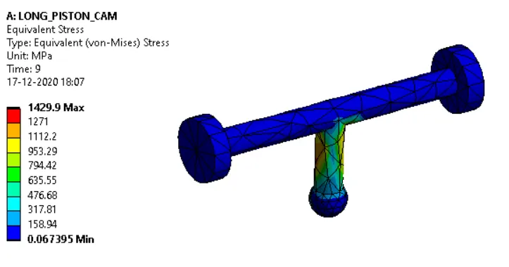
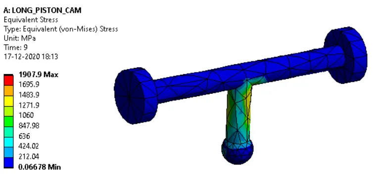
EQUIVALENT STRESS:
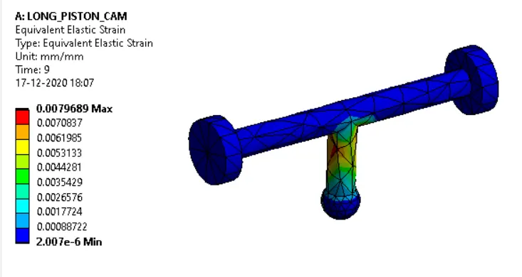
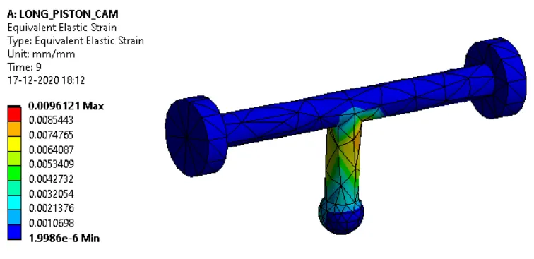
EQUIVALENT STRAIN:
CASE-2: FRICTIONAL CONTACT WITH COEFFICIENT OF FRICTION OF 0.1.
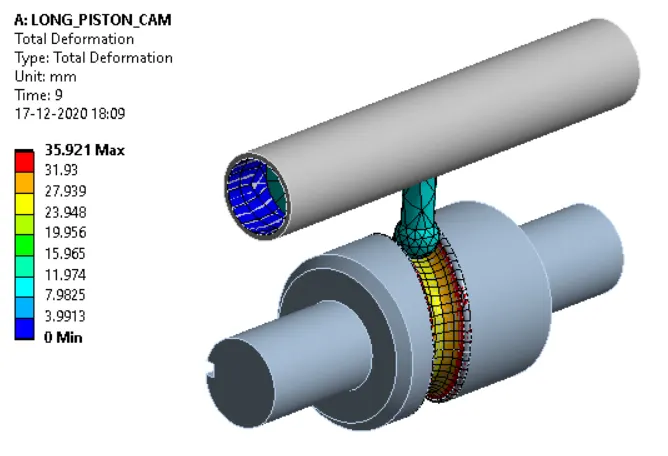
TOTAL DEFORMATION:
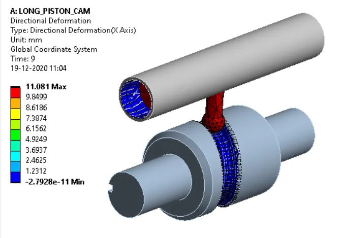
DIRECTIONAL DEFORMATION:
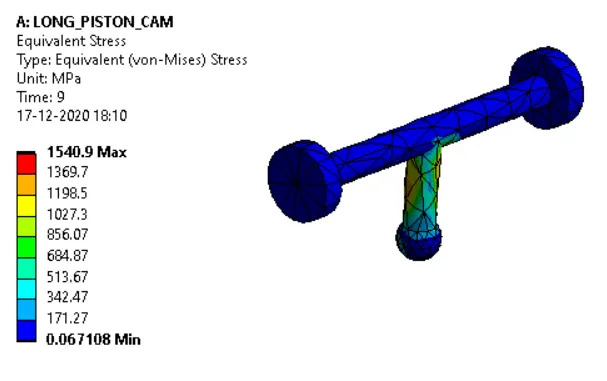
EQUIVALENT STRESS:
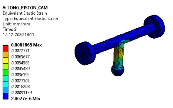
EQUIVALENT STRAIN:
CASE-3: FRICTIONAL CONTACT WITH COEFFICIENT OF FRICTION OF 0.2.
TOTAL DEFORMATION:
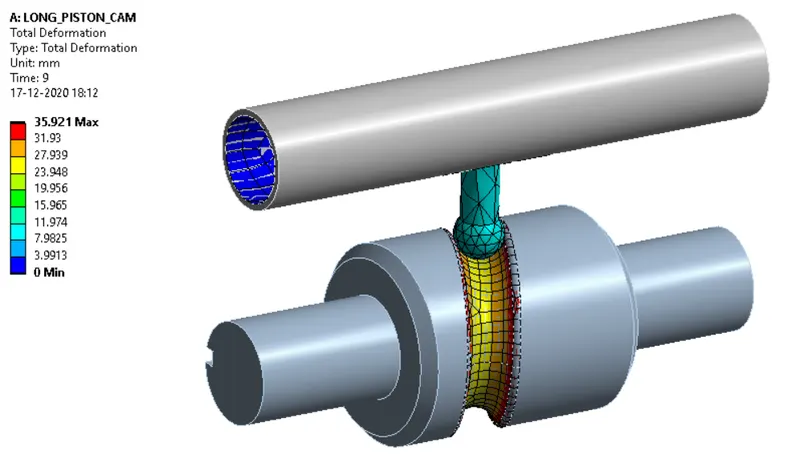
DIRECTIONAL DEFORMATION:
EQUIVALENT STRESS:
EQUIVALENT STRAIN:
COMPARISON:
| DIRECTIONAL DEFORMATION | EQUIVALENT STRESS | EQUIVALENT STRAIN | |
| CASE-1 | 11.039 mm | 1429.9 Mpa | 0.0079689 |
| CASE-2 | 11.081 mm | 1540.9 Mpa | 0.0081865 |
| CASE-3 | 11.127 mm | 1907.9 Mpa | 0.0096121 |
CONCLUSIONS:
- The transient structural analysis on the long-piston-cam is performed successfully.
- The results of the three simulation cases are found successfully.
- The equivalent stress and equivalent elastic strain incase of analysis with frictional contact are less compared to the equivalent stress and equivalent elastic strain in case of the analysis with frictional contact with a coefficient of friction of 0.1 and 0.2 because friction is the force resisting the relative motion between two contacting surfaces, Hence when we have a higher coefficient of friction the resistance to motion is reduces hence it develops more deformation this results in higher equivalent stress and strains.