WELD_VERIFICATION_USING_ANSYS_STUCTURAL
AIM:
- To simulate different types of welding using three different materials.
- To find out directional deformation equivalent stress in each case and compare the results from three cases.
Procedure:
- Open ansys workbench.
- Open static structural analysis system and rename it as weld verification.
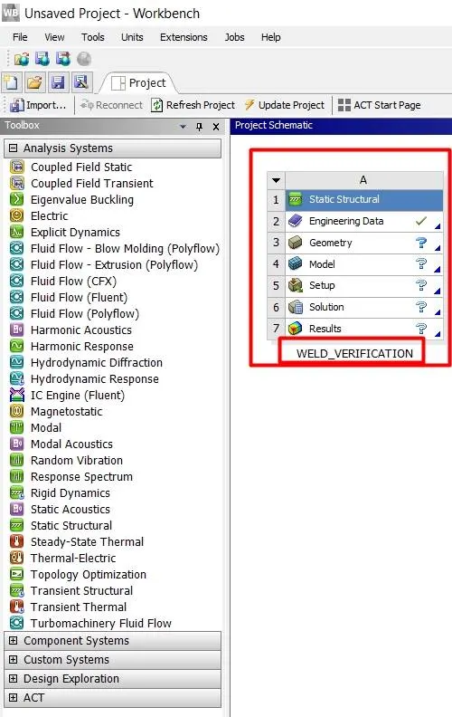
- Open engineering data and add material that is Stainless Steel, Aluminium Alloy(high strength, wrought), and Bronze
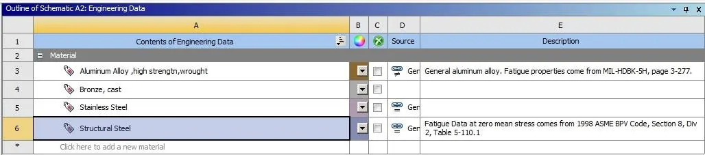
MATERIAL PROPERTIES:
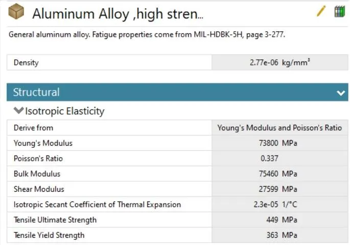
aluminium alloy,(high strength, wrought):
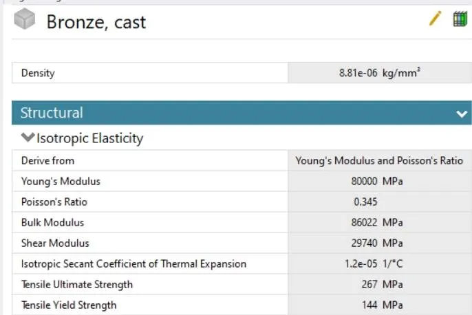
Bronze, Cast:
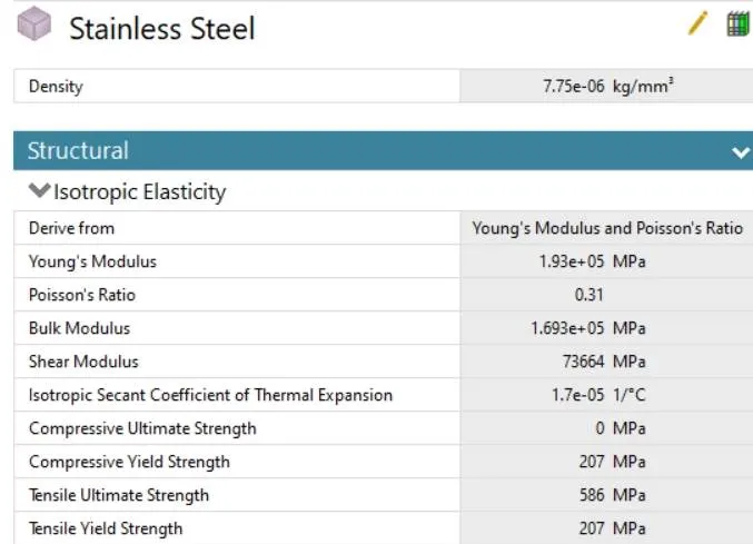
Stainless steel:
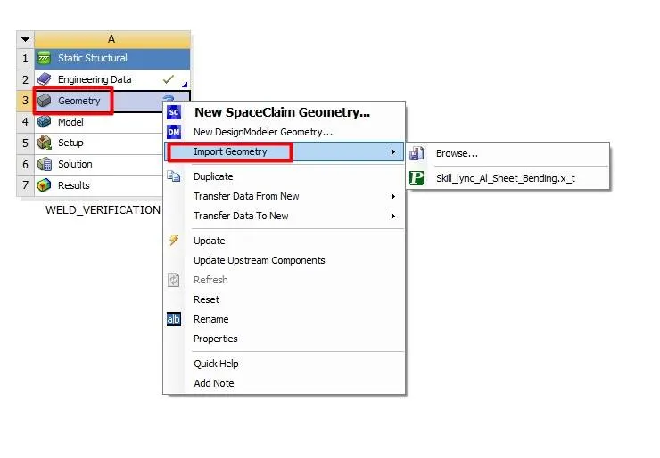
- Now right click on geometry and import geometry.
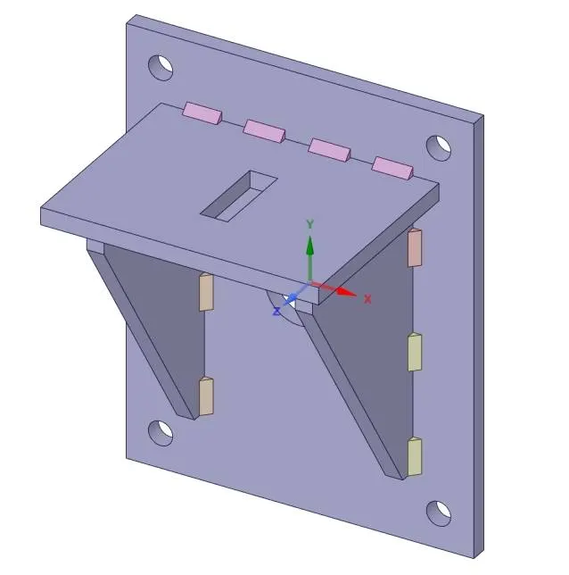
- Check whether cad geometry is properly imported or not using SpaceClaim.
- Open ansys mechanical for meshing and setup of simulation.
- Rename the parts for convenience.
CASE_1:
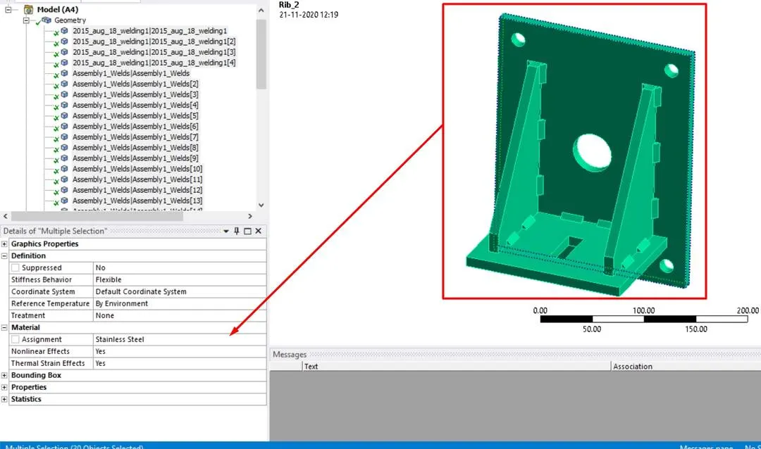
- Assign the material as stainless steel.
- Go to connections and right-click on the contact group and select rename based on the definition.
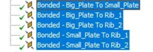
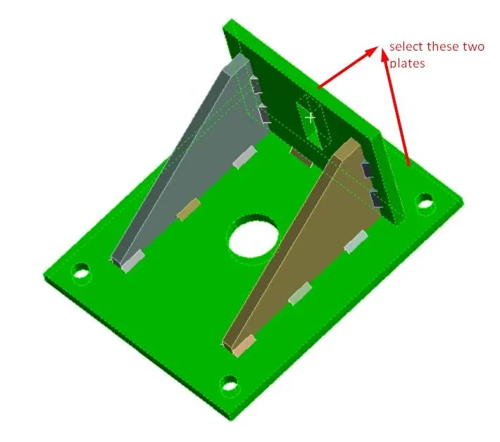
- Select the bottom five contacts in the contact group which are related to the contacts between big plate small plate and ribs.
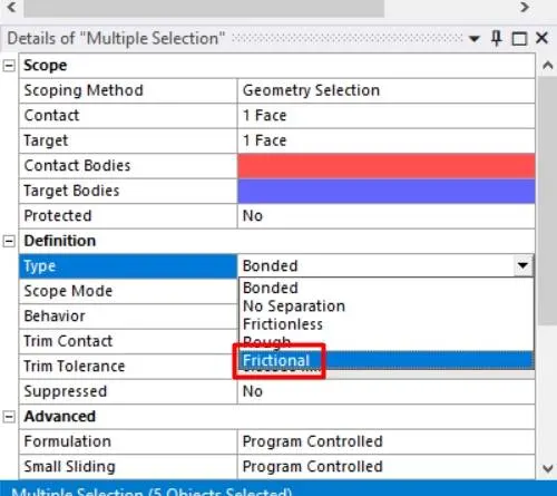
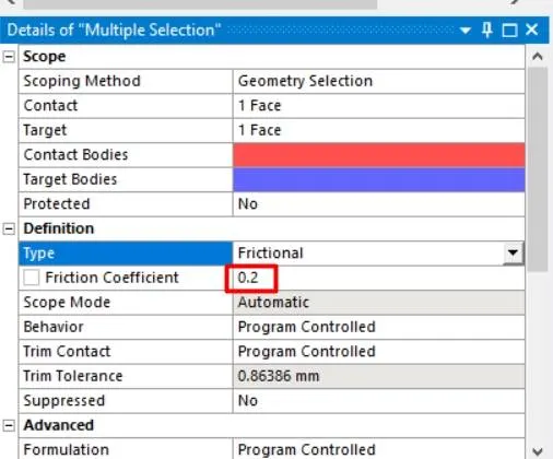
- Change the contact type to frictional with a coefficient of friction of 0.2.
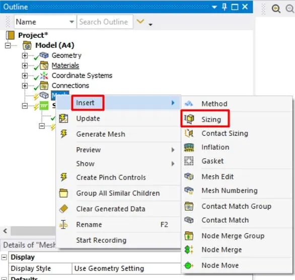
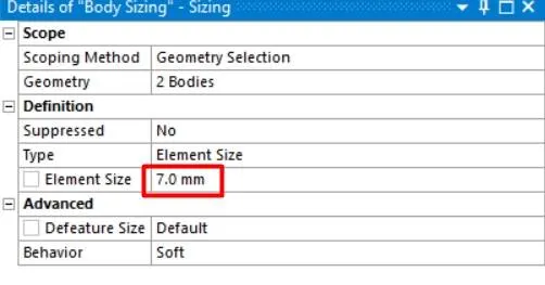
- Now go to mesh tab and inset the body sizing of 7 mm to the small and big plate and generate the mesh with default values by ansys.
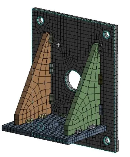
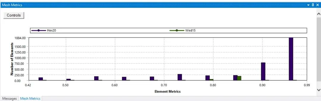
- The above graph shows mesh metrics which give the quality of the mesh and the type and number of elements.
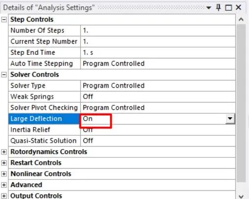
- Now go to the analysis setting the simulation is a single-step simulation thus time stepping is not required for the simulation.
- Turn on the large deflection.
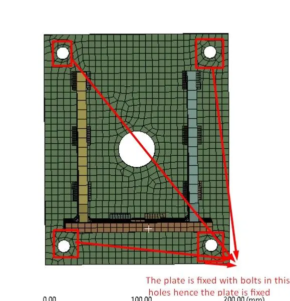
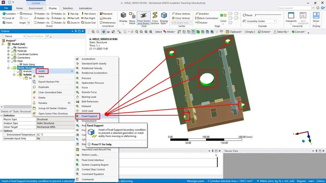
- Now the big plate is bolted to the wall and load is applied on the small plate hence fix the big plate by selecting the geometry of the holes as below.
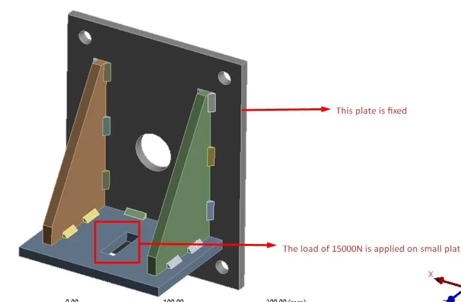
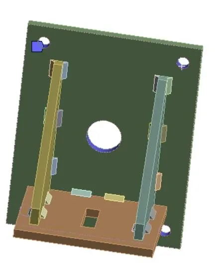
- Apply a load of 15000N on the small plate as below.
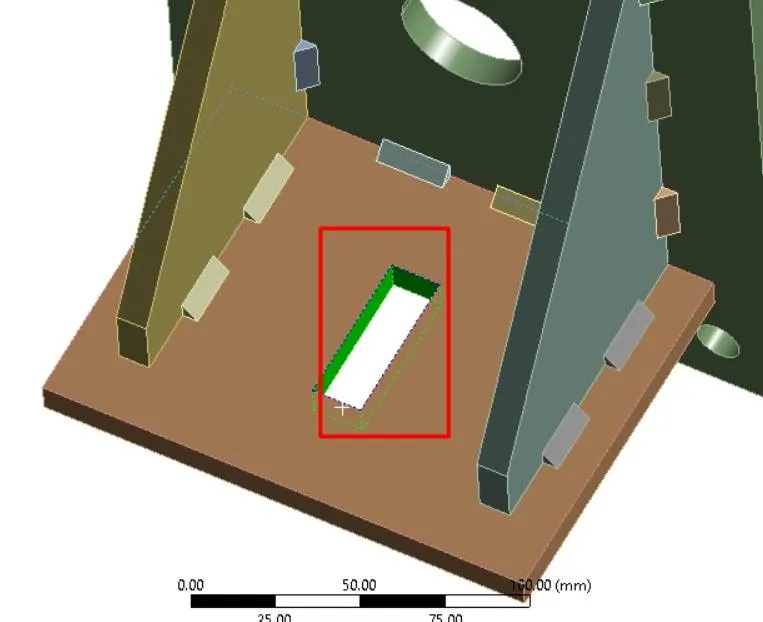
- Select the surface around the hole using a surface filter.
- Insert the load as below.
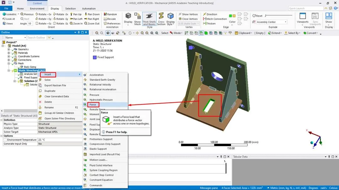
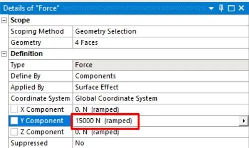
- Now add the output results required.
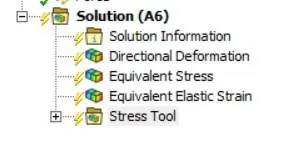
- To look at equivalent stress in weldments add an equivalent stress probe and select the geometries of weldments and apply.
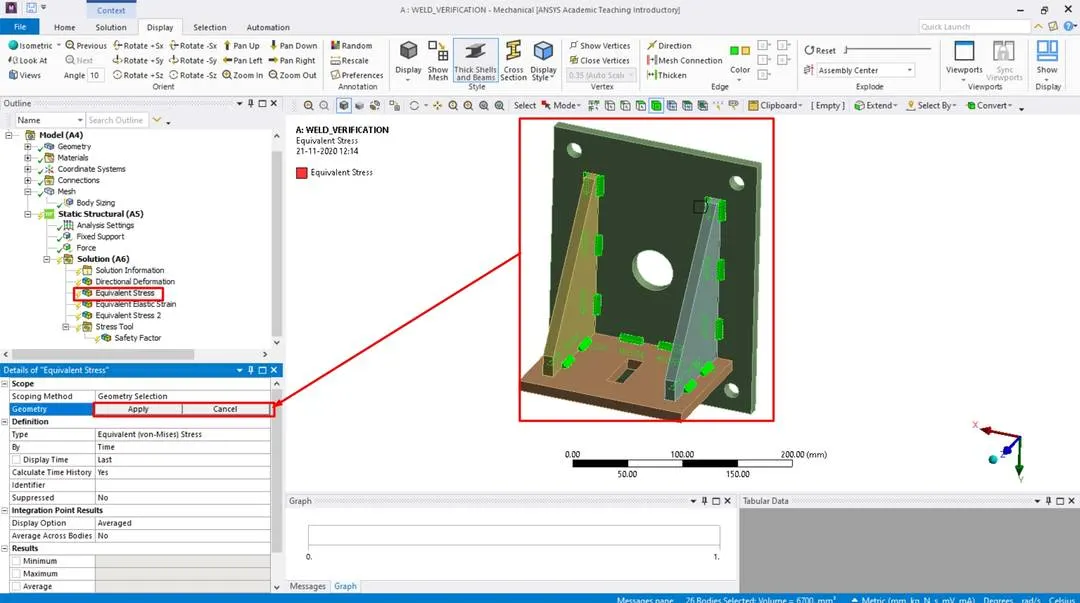
- Now run the simulation to obtain results.
CASE-1 RESULTS:
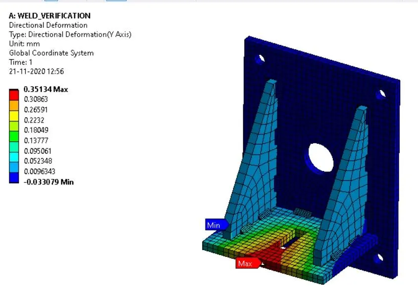
Directional deformation:
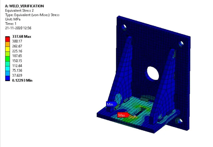
Overall Equivalent stress:
Equivalent stress in welds:
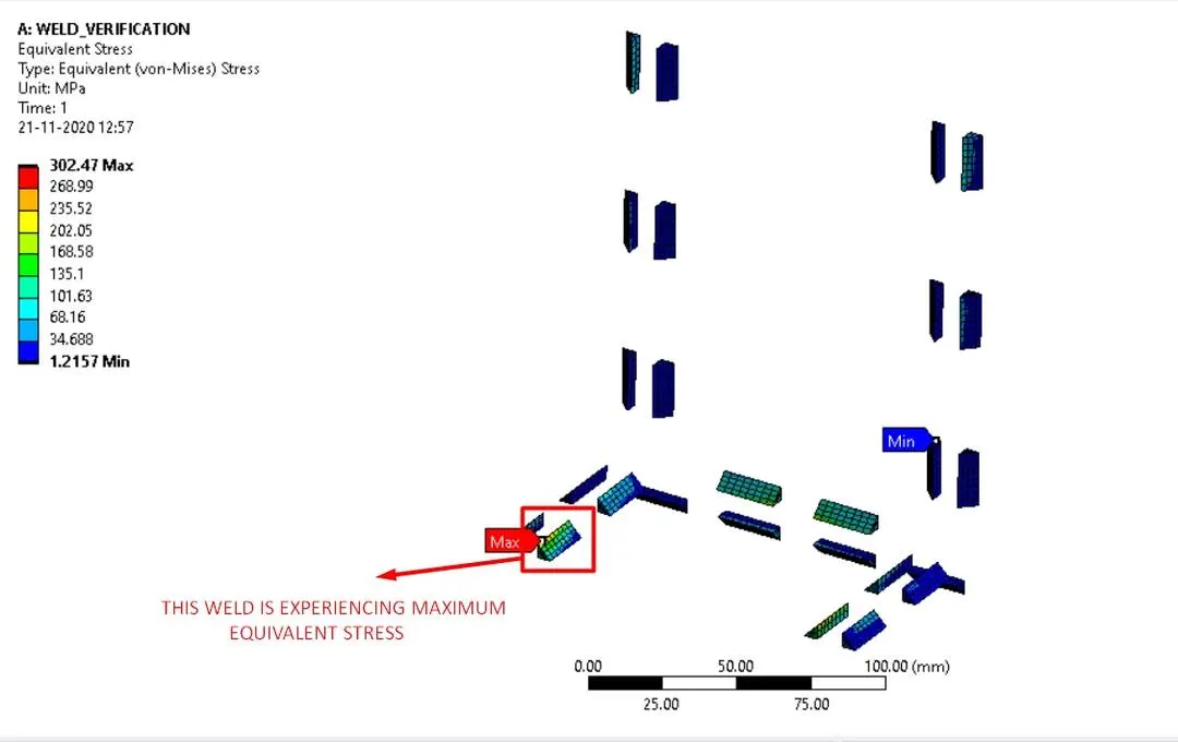
- The weld highlighted in the above image experiences more stress than other welds.
Safety factor:
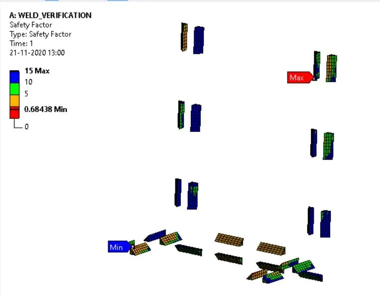
- The above figure represents the safety factor the weldments which are having a safety factor value less than 1 will experience a high amount of stress and undergoes failure.
CASE_2:
- Assign material as for this case is Aluminium alloy(high strength, wrought). [Plate material to be used is stainless steel].
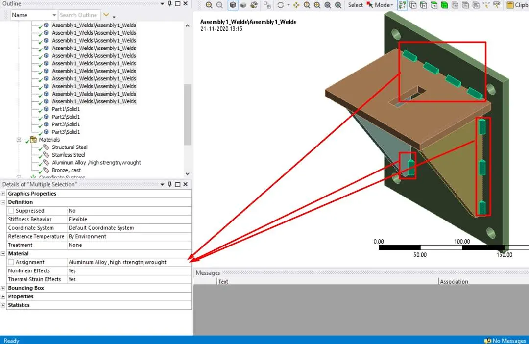
- Now set up the simulation by following the procedure as in case-1.
- Now run the simulation to obtain results.
CASE-2 RESULTS:
Directional deformation:
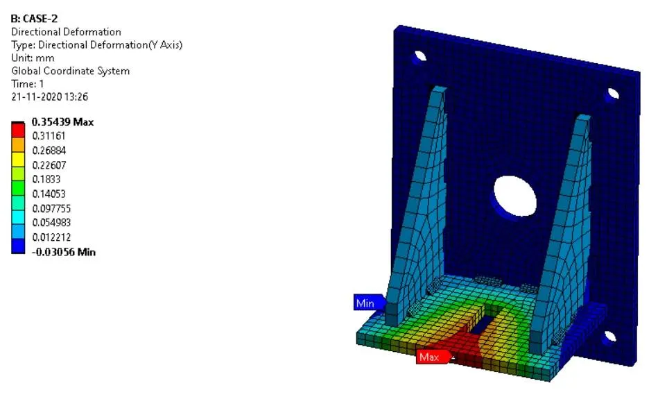
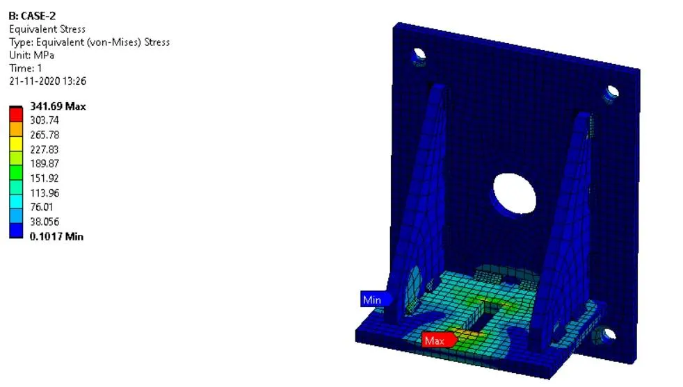
Overall Equivalent stress:
Equivalent stress in welds:
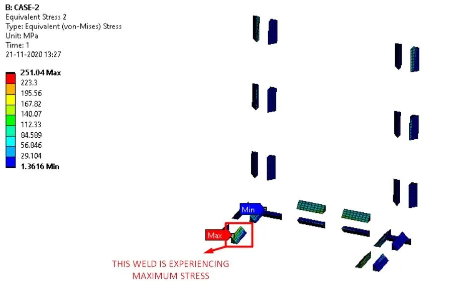
- The weld highlighted in the above image experiences more stress than other welds.
Safety factor:
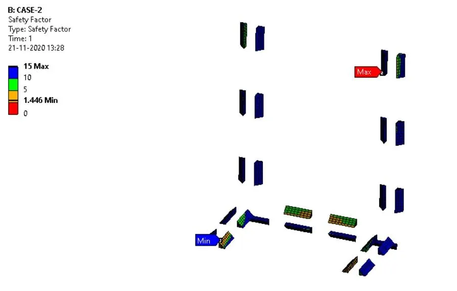
- The above figure represents the safety factor of the welds in case-2 all the weld have a safety factor of above 1 hence the design is safe with the given materials and loading conditions.
CASE_3:
- In order to simulate "Brazing", assign bronze as the weld material. Assign Stainless Steel to both plates and Copper to the "Ribs".
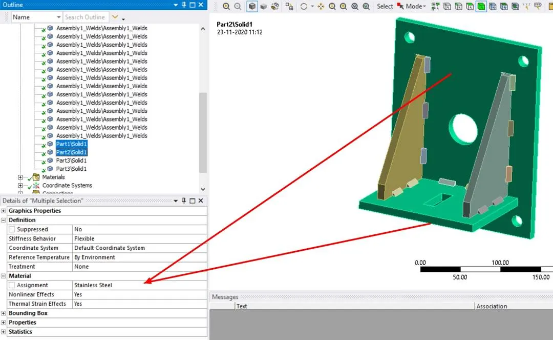
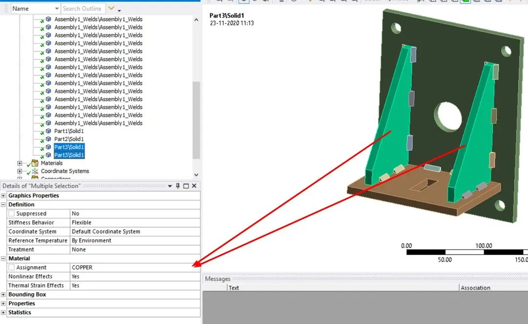
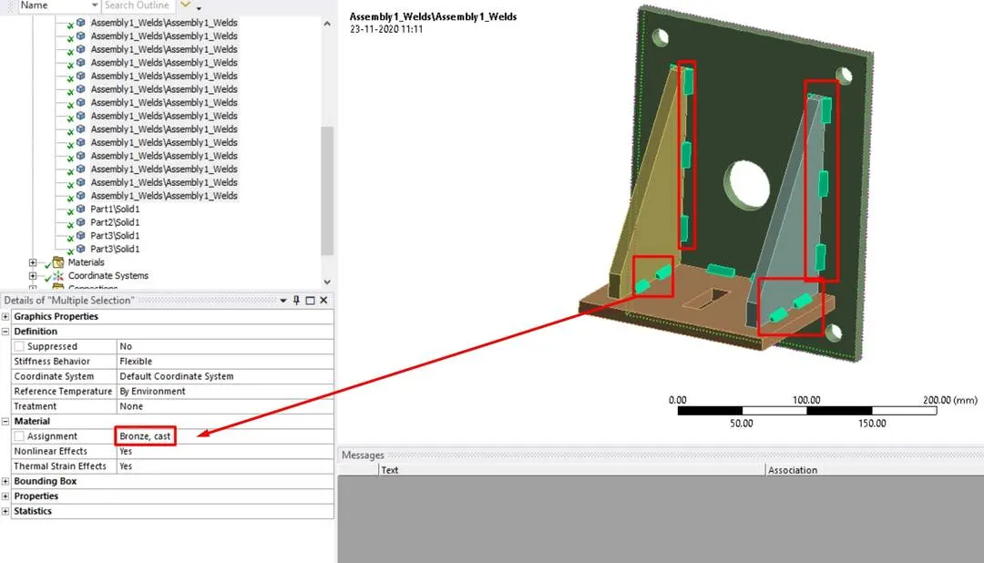
- Now run the simulation using a similar setup as in case-1 to obtain the required results.
CASE-3 RESULTS:
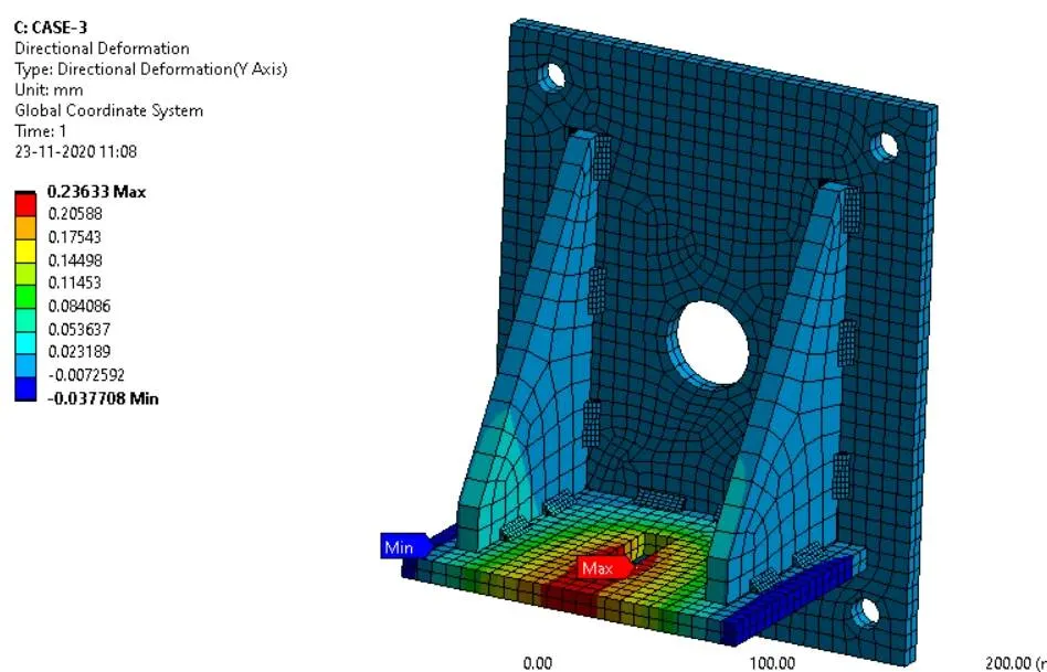
DIRECTIONAL DEFORMATION:
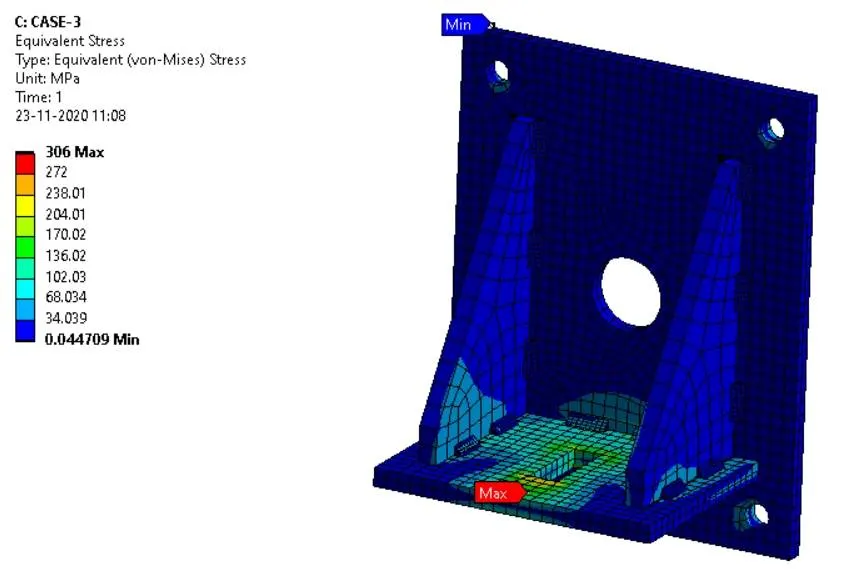
OVERALL EQUIVALENT STRESS:
EQUIVALENT STRESS ON WELDS:
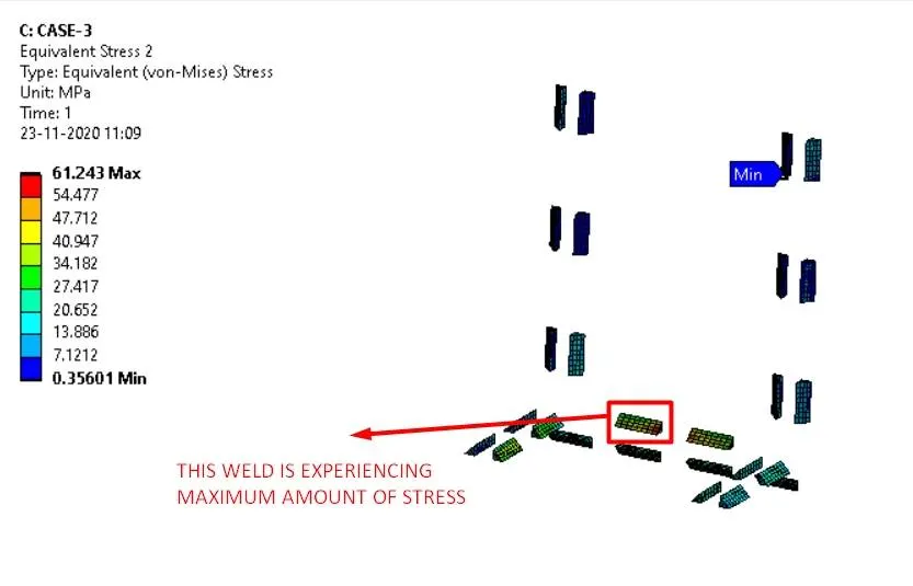
- The weld highlighted in the above image experiences more stress than other welds.
SAFETY FACTOR:
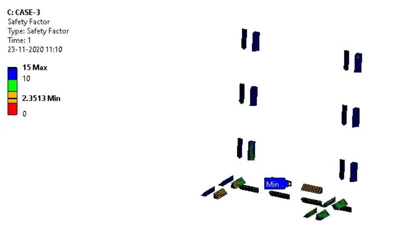
- The above figure represents the safety factor of the welds in case-3 all the weld have a safety factor of above 1 hence the design is safe with the given materials and loading conditions.
RESULTS:
| CASES/RESULTS | CASE-1 | CASE-2 | CASE-3 |
| DIRECTIONAL DEFORMATION | 0.35134 mm | 0.35349 mm | 0.23633 mm |
| OVERALL EQUIVALENT STRESS | 337.68 Mpa | 341.69 Mpa | 306 Mpa |
| EQUIVALENT STRESS ON WELDS | 302.47 Mpa | 251.04 Mpa | 61.243 Mpa |
| SAFETY FACTOR(MIN) | 0.68438 | 1.446 | 2.3513 |
CONCLUSIONS:
- All the simulations are performed successfully and results are tabulated
- The Given design fails in case-1 simulation for a given material and loading conditions and the design is safe for the other two cases i.e., case-2 and case-3 in which in case-2 material used is Aluminium alloy(high strength, wrought). [Plate material to be used is stainless steel]. In case-3 material used is copper for ribs, Stainless steel for plates and bronze for welds.
- Among all the three cases case-3 gives much better results compared to case-1 and case-2 in case-3 the design experiences less amount of stresses.