Week 1 Spur Gear Challenge
OBJECTIVE:
- To perform structural analysis for the given spur gear geometry using Ansys workbench using three different materials to evaluate the equivalent stress and deformation and stress sensitivity developed due to applied boundary conditions and to find which material is more suitable for spur gear manufacturing.
PROCEDURE:
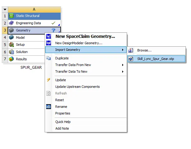
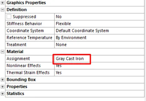
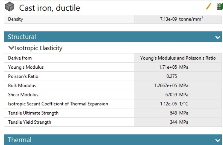
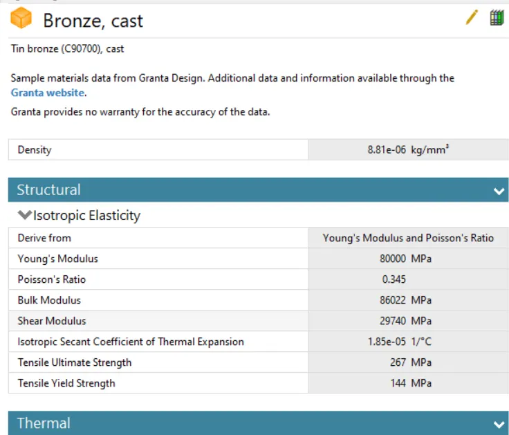
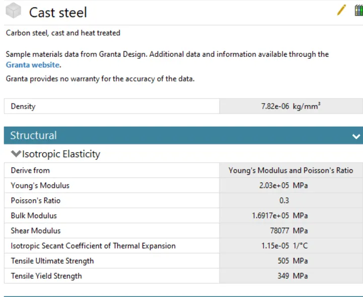
- Import spur gear geometry and assign material cast iron (ductile), cast steel, and cast bronze.
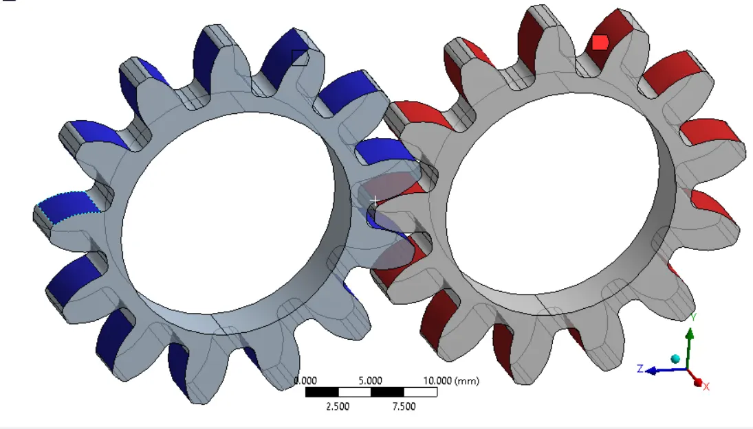
- Under connections insert contact group and create frictional contact between the tooth faces, As shown below.
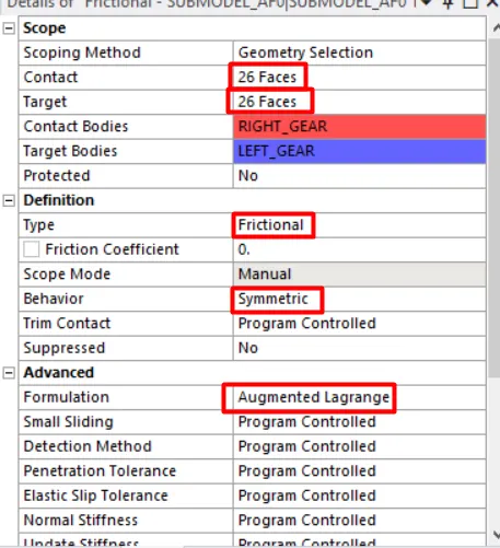
- Change the behaviour of contact to symmetric and contact formulation as augmented Lagrange.
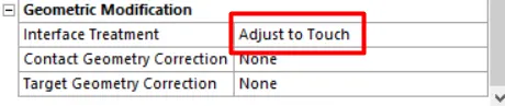
- Change interface treatment to adjust to touch as shown below.
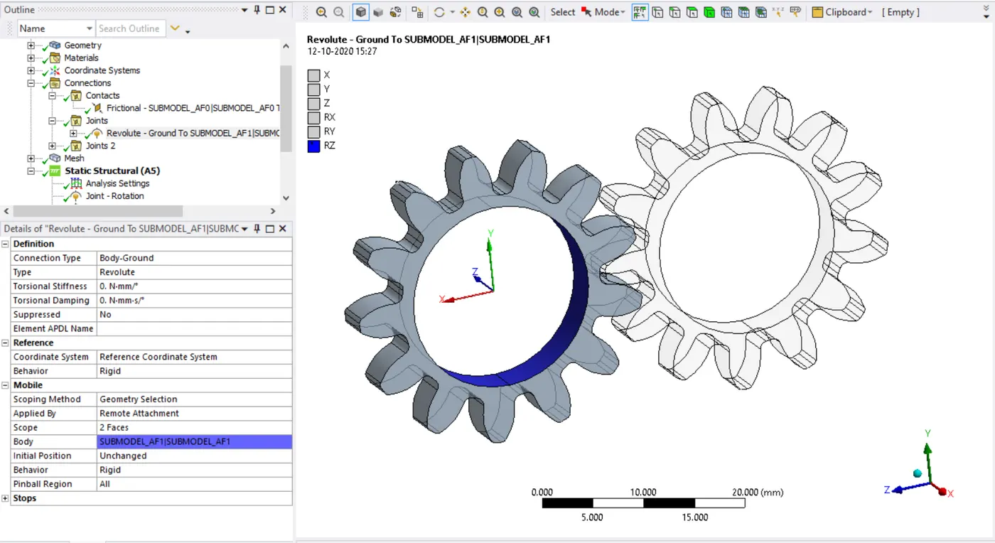
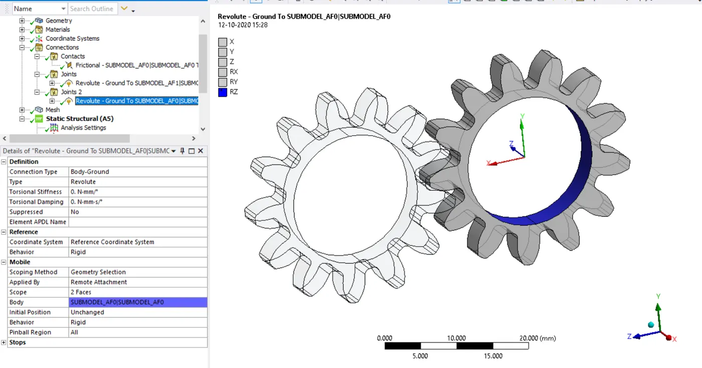
- Now create revolute joints for both the spur gears with the frame of reference that is with the body to ground option.
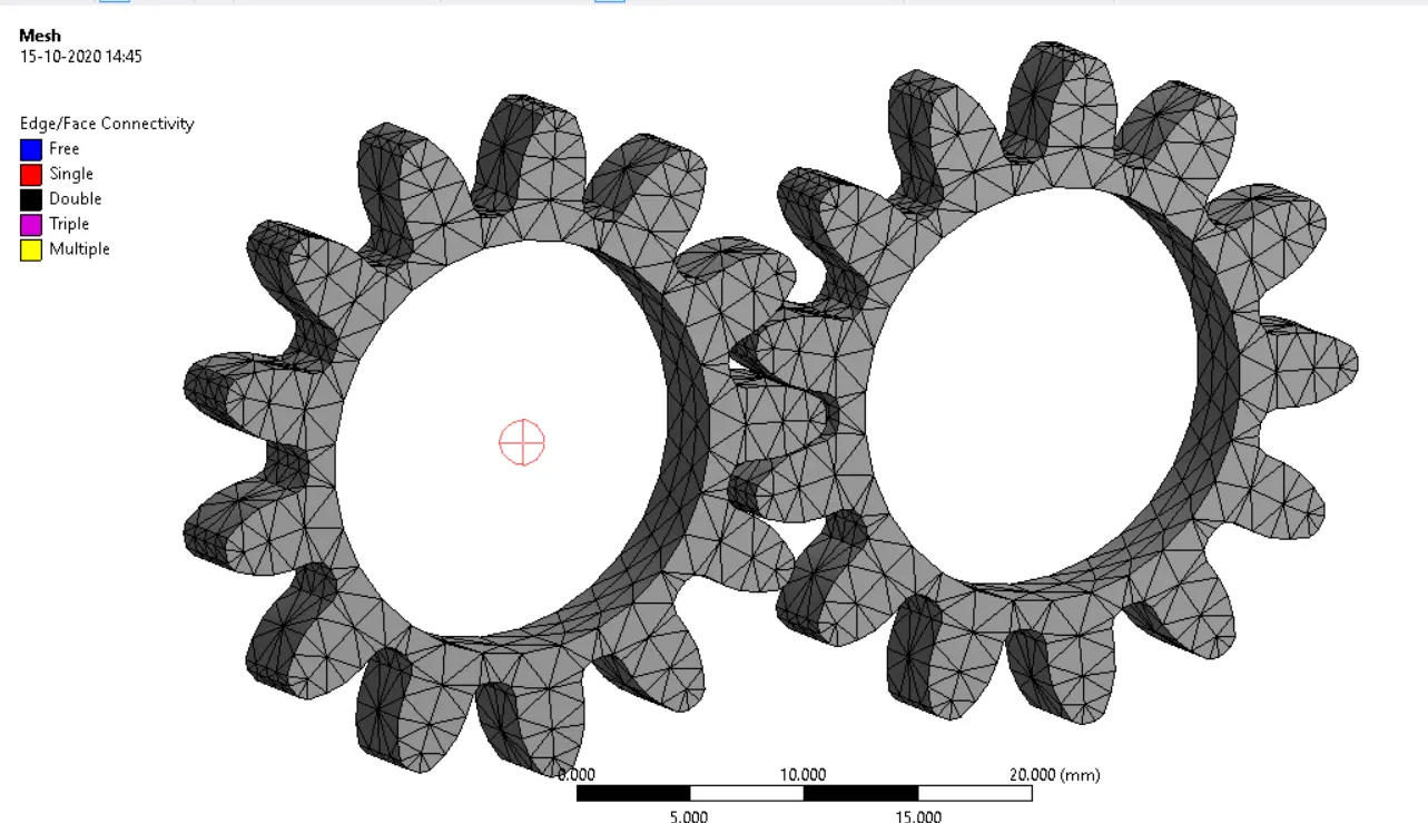
- Now go to mesh and insert mesh method and assign geometry to mesh and mesh the model using tetrahedrons with minimum element size as 2 mm and change element order to linear, Mesh as below.
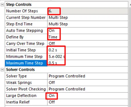
- Now go to analysis settings and change the number of substeps to 6 and make necessary settings as below and turn on the large deflection option.
- Now insert joint loads as rotation and moment in the tabular format for all the steps.
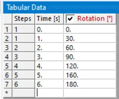
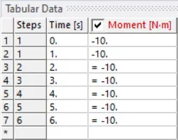
- Now under solution insert Total deformation, Equivalent stress, and stress intensity.
- Now solve the model to simulate the results.
RESULTS:
| SL.NO | MATERIAL | EQUIVALENT STRESS | TOTAL DEFORMATION | STRESS INTENSITY | YIELD STRENGTH | FACTOR OF SAFTEY |
| 1 | CAST IRON | 185.52Mpa | 30 mm | 205.71 Mpa | 344 Mpa | 1.85 |
| 2 | CAST STEEL | 186.68 Mpa | 30 mm | 204.66 Mpa | 349 Mpa | 1.86 |
| 3 | CAST BRONZE | 178.4 Mpa | 30 mm | 198.72 Mpa | 144 Mpa | 0.80 |
TOATL DEFORMATION:
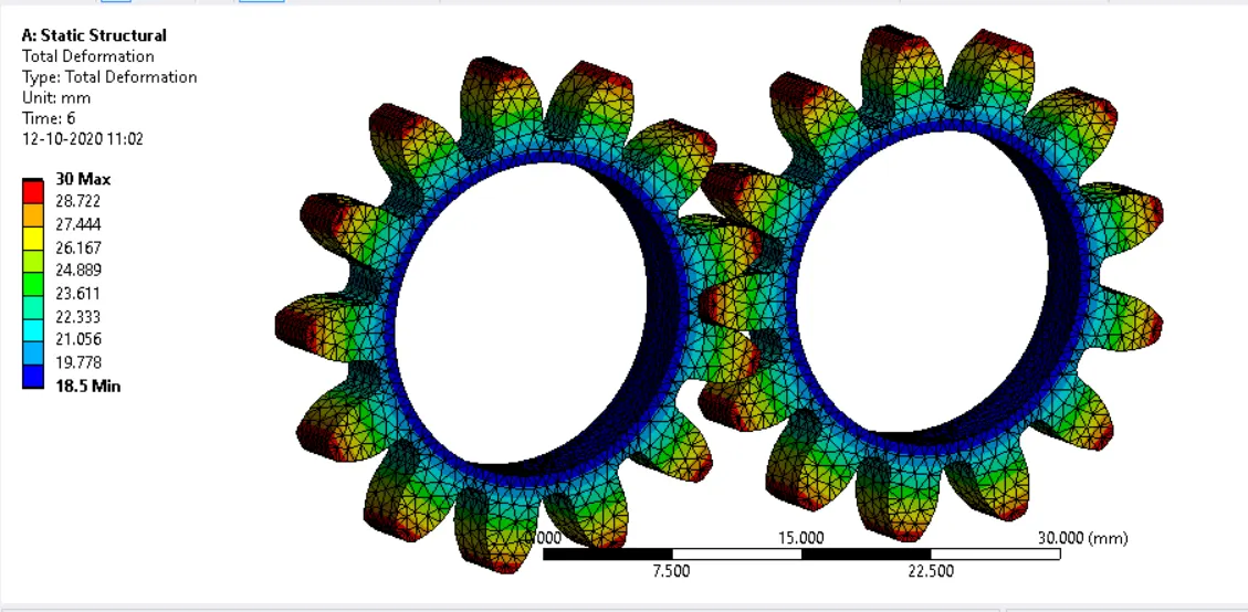
CAST IRON: 30MM.
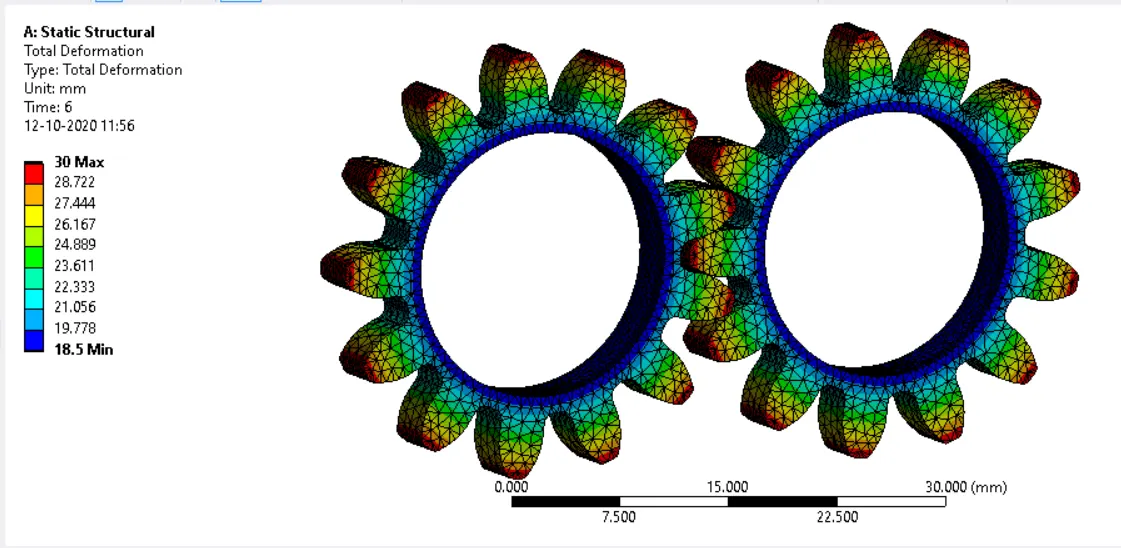
CAST STEEL: 30MM.
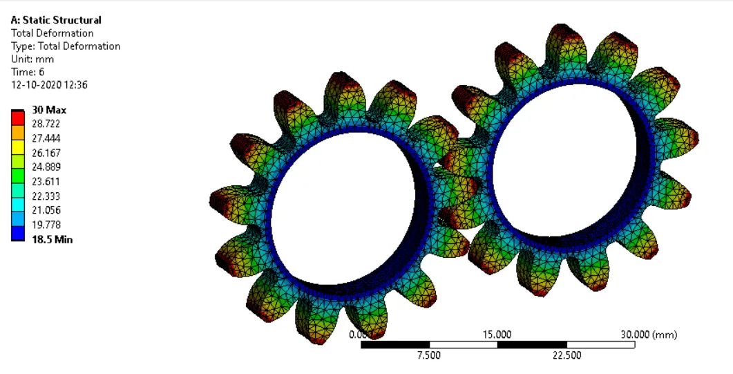
CAST BRONZE: 3OMM.
EQUIVALENT STRESS:
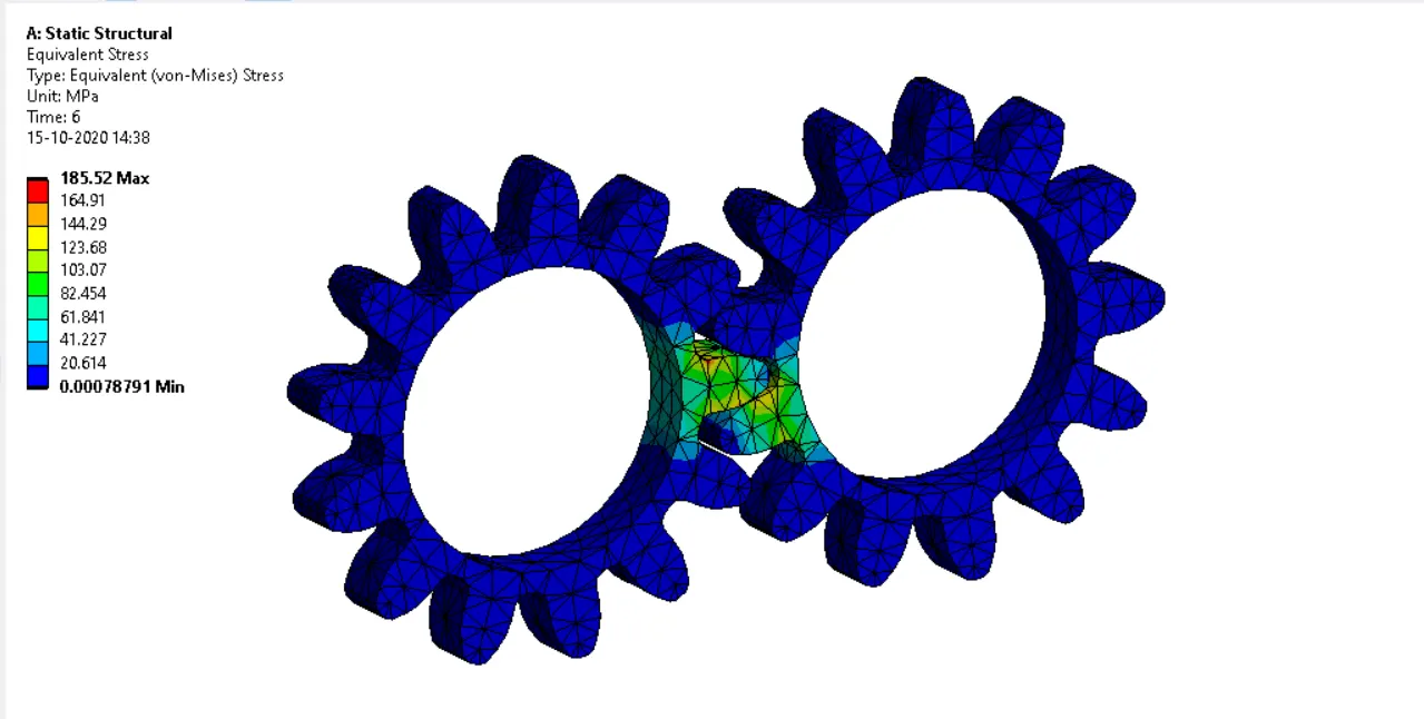
CAST IRON: 185.52Mpa.
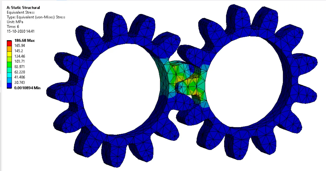
CAST STEEL: 186.68Mpa.
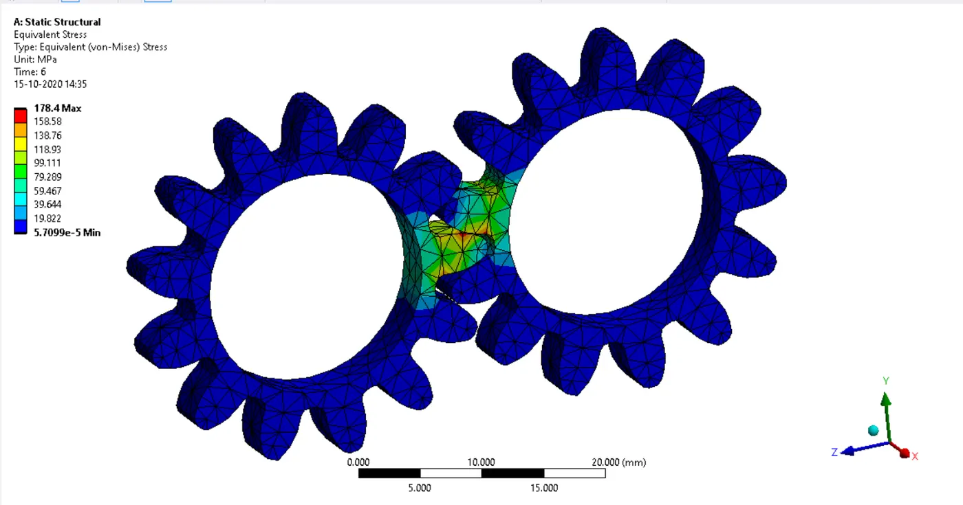
CAST BRONZE: 178.4Mpa.
STRESS INTENSITY:
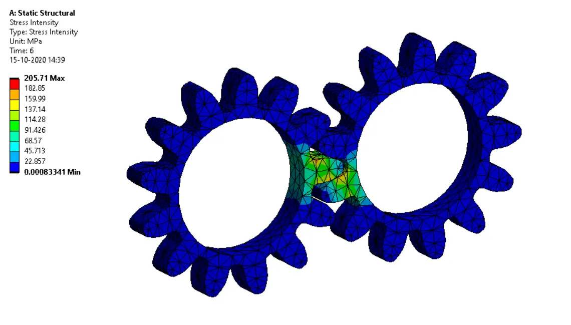
CAST IRON: 205.71 Mpa.
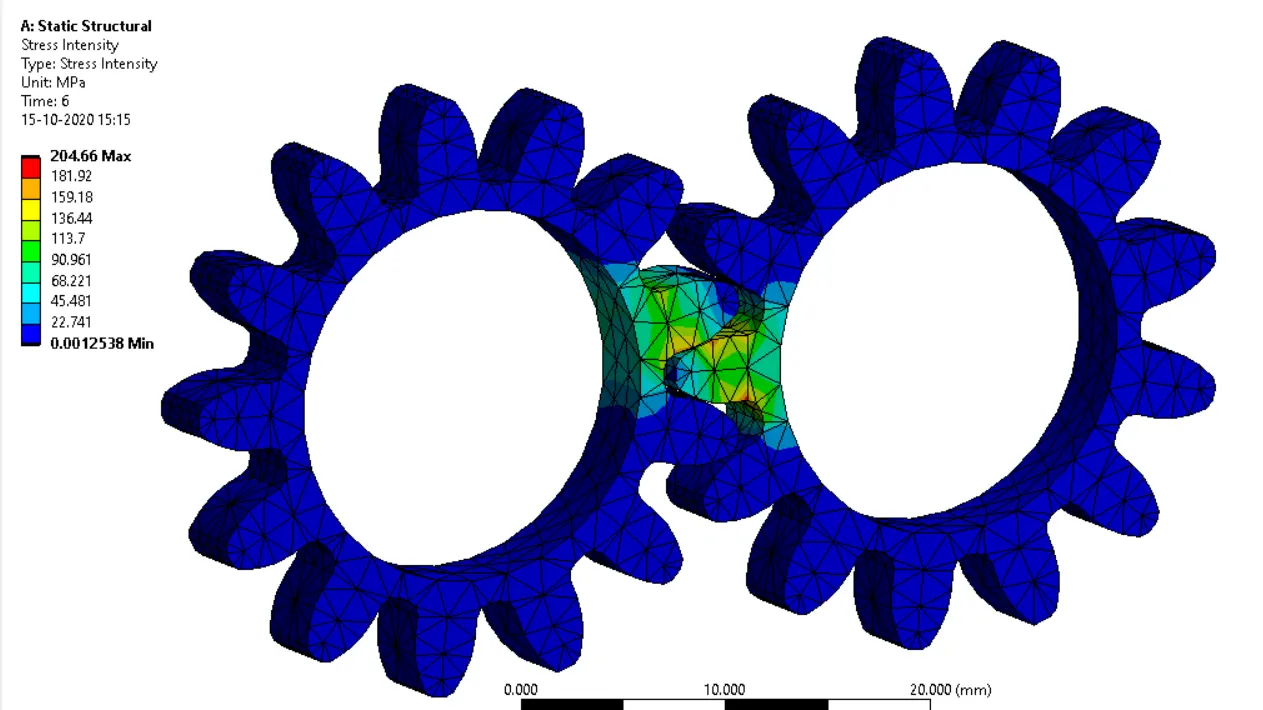
CAST STEEL: 204.66 Mpa.
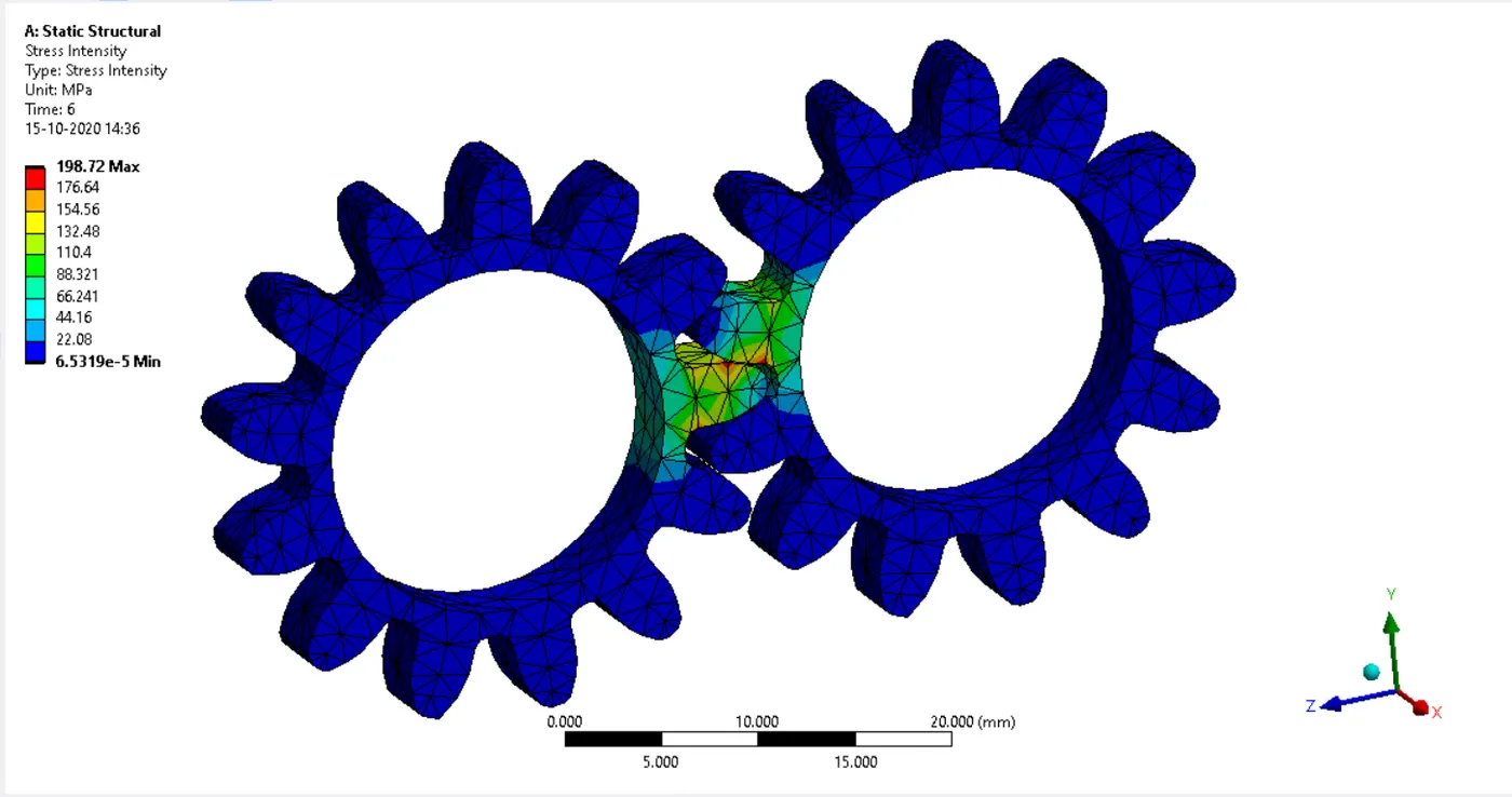
CAST BRONZE: 198.72 Mpa.
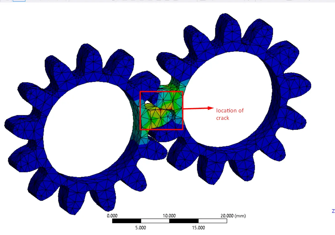
- The location of crack may occur at the point where the stress intensity is very high or maximum.
- To decide a design is safe or not for the given boundary conditions is identified by calculating the factor of safety by using von mises stress obtained from the simulation and the yield strength of the material. The factor of safety should be greater than 1 then the design is said to be safe for the applied boundary conditions.
The factor of safety:
For CAST IRON:
FACTOR SAFETY= YIELD STRENGTH/MAXIMUM STRESS= 344/185.52
= 1.85 (DESIGN IS SAFE FOR THE GIVEN BOUNDARY CONDITIONS).
For CAST STEEL:
FACTOR SAFETY= YIELD STRENGTH/MAXIMUM STRESS= 349/186.68
= 1.86 (DESIGN IS SAFE FOR THE GIVEN BOUNDARY CONDITIONS).
For CAST BRONZE:
FACTOR SAFETY= YIELD STRENGTH/MAXIMUM STRESS= 144/178.4
= 0.80 (DESIGN IS NOT SAFE FOR THE GIVEN BOUNDARY CONDITIONS).
CONCLUSION:
- From the above, in all the simulation cases the cast bronze material is failing for the given boundary conditions as the factor of safety falls below 1. So cast bronze is not suitable for the fabrication of spur gears.
- For the cast steel and cast iron, the factor of safety is 1.85 ad 1.86 so those two materials are safe for the design. The stress intensity in both cases is almost equal.
- But because of the cheaper cost than cast steel and less labor required to produce the final product cast iron is more suitable for spur gear fabrication.