Week 2 Bevel Gear Challenge
GRID DEPENDENCY TEST:
While performing finite element analysis one of the most common questions is finite element mesh quality. How can we know the mesh quality is good enough for the analysis? Mesh density is the significant metric used to control the accuracy. Assuming no singularities are present, a high-density mesh will produce results with high accuracy. However, if a mesh is too dense it will require a large amount of computer memory and long run times especially for multiple-iteration runs that are typical of non-linear and transient analysis.
The most fundamental method of checking the mesh quality is to refine a mesh until a critical result such as equivalent stress does not change significantly with each refinement. This is a grid dependency test, where, analysis begins with a coarse mesh and it is refined to finer mesh for each run until the results do not change significantly and depend on the grid size anymore. As the grid size approaches zero the approximate solution is almost equal to the actual solution. The aim of the test is to find the optimum mesh size for the solution. Where is neither too coarse to produce inaccurate results neither too fine, where it will consume a lot of computing efforts and time.
AIM:
- To perform bevel gear simulation using ansys workbench.
- To perform grid dependency test with an element size of 4 mm, 5 mm, 6 mm for the bevel gear to find the optimum mesh size for the simulation.
PROCEDURE:
- Open ansys workbench and drop a static structural analysis system and rename it as bevel-gear simulation.
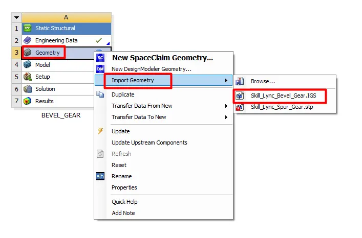
- Import geometry by browsing to file location and edit geometry using SpaceClaim.
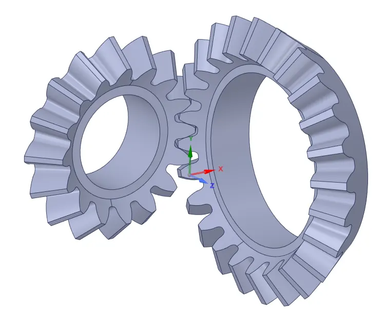
- Close Spaceclaim and open ansys mechanical to set up the simulation.
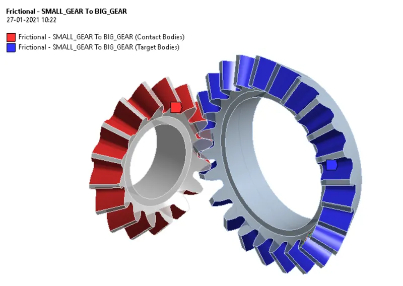
- Create a frictional contact between the two gears.
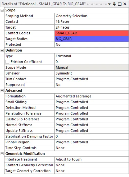
- Change contact behavior to symmetric and formulation to augmented Lagrange, Change the interface treatment to adjust to touch.
- Create a body to ground revolute joints for the two gears.
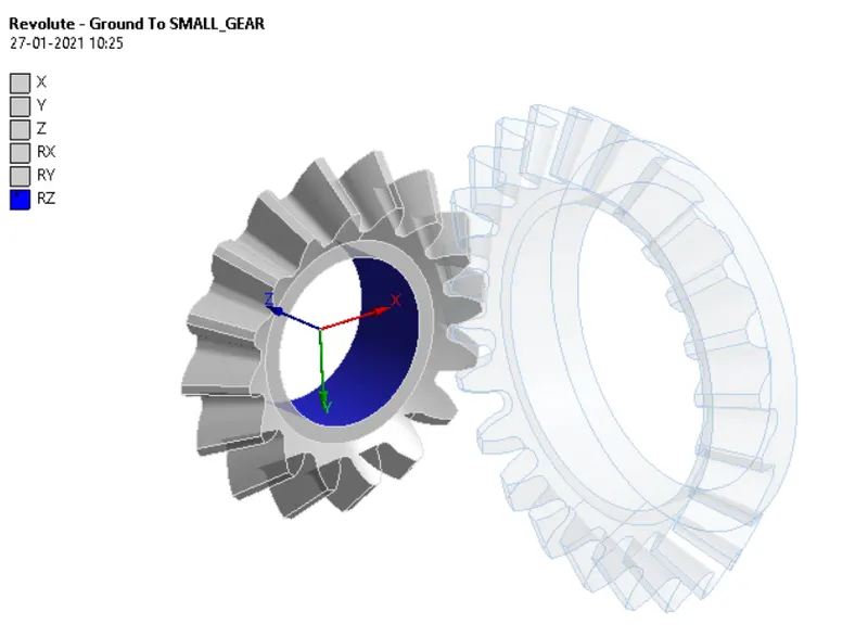
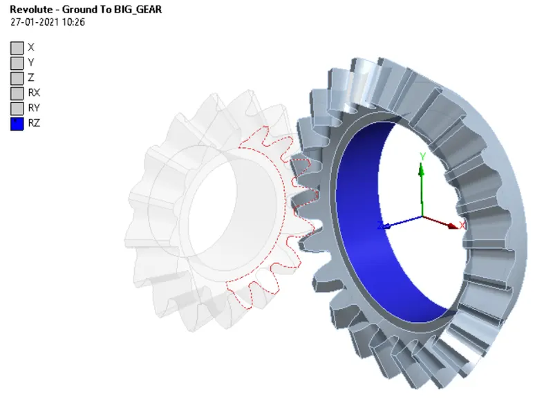
- Now to perform the grid dependency test simulate the model with the three different element sizes i.e., 4mm, 5mm, and 6mm.
- Insert face sizing of 1.75mm for the faces in contact.
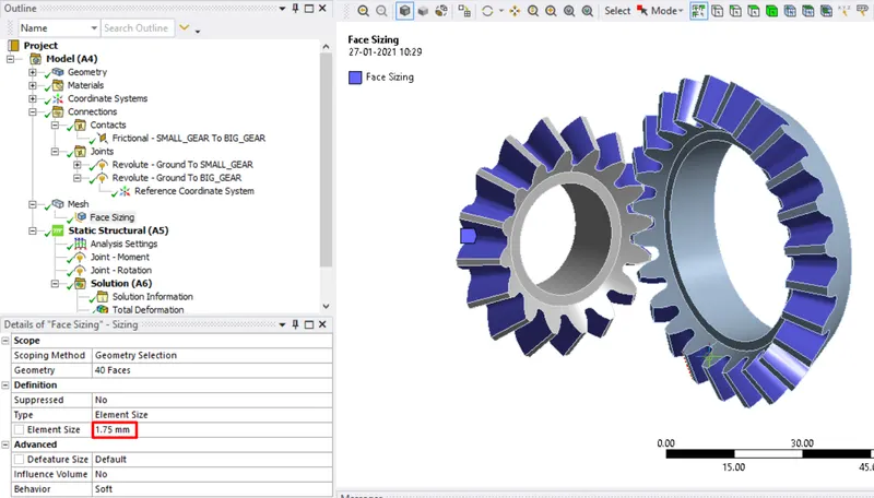
- Generate the mesh it gives the mesh with an element size of 6 mm.
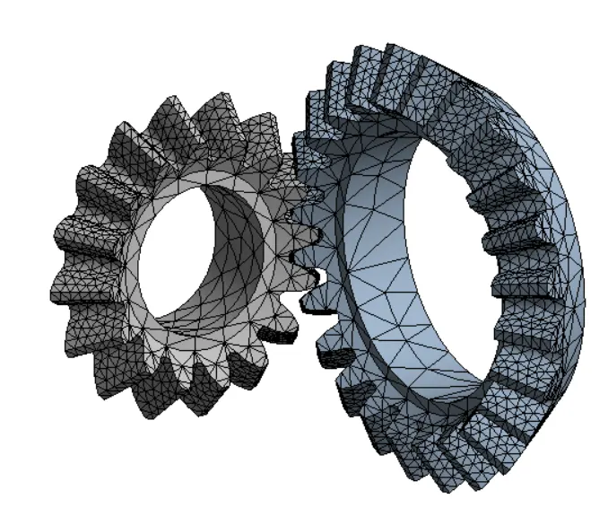
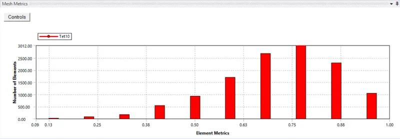
- The above graph represents the mesh metric which gives a clear idea about element quality and the type of elements used for the simulation.
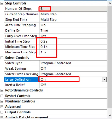
- Now under the analysis setting change the number of steps to 6 select all the steps, and change the initial time step to 0.1 minimum time step to 0.005, and maximum time step to 1s.
- Turn on the large deflection and change weak springs to program-controlled.
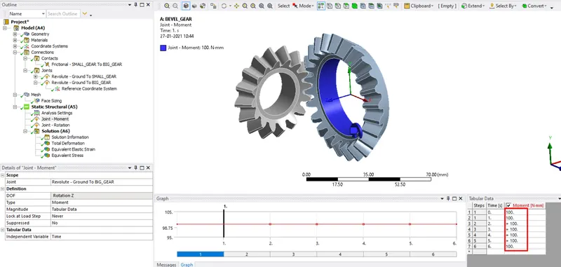
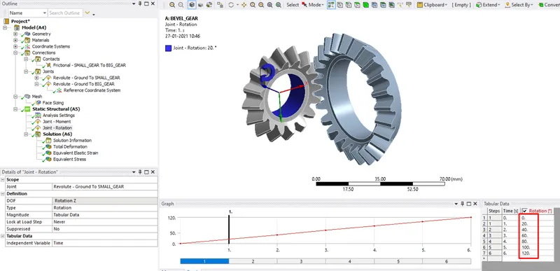
- Now inset the joint load as a moment for the big gear in tabular form and rotation for the small gear in tabular form.
- Now list the outputs require and create a parametric set for the outputs and run the simulation for 6 mm mesh.
- Repeat the same procedure to simulate the model with an element size of 4mm and 5mm. Or perform the simulation by creating a parametric set for element size to obtain results.
RESULTS:
CASE-1: MESH SIZE-4 mm:
TOTAL DEFORMATION, EQUIVALENT STRESS, AND EQUIVALENT ELASTIC STRAIN:
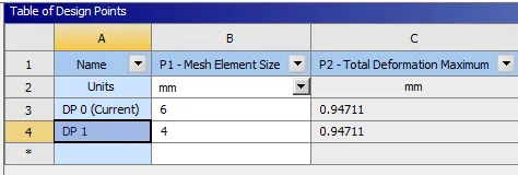
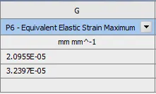
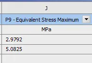
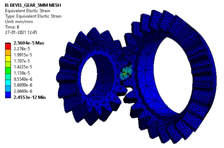
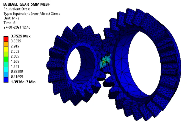
CASE-2: MESH SIZE-5 mm:
TOTAL DEFORMATION:
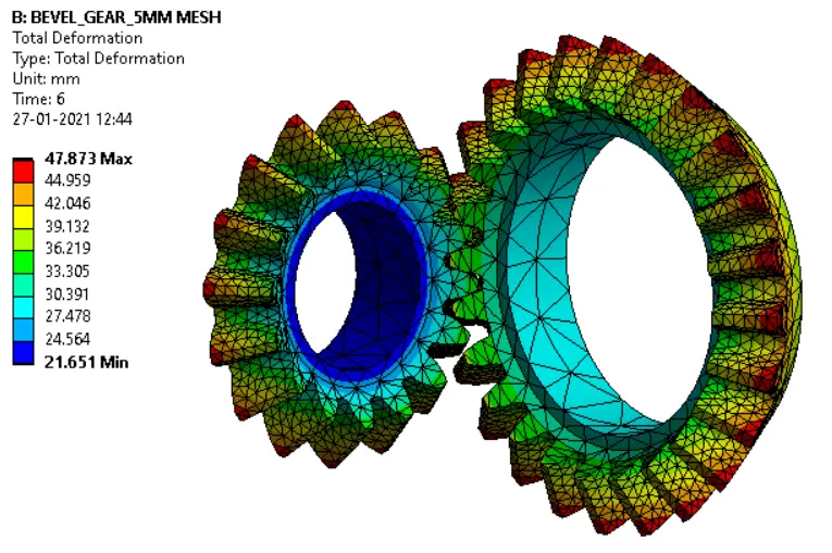
EQUIVALENT ELASTIC STRAIN:
EQUIVALENT STRESS:
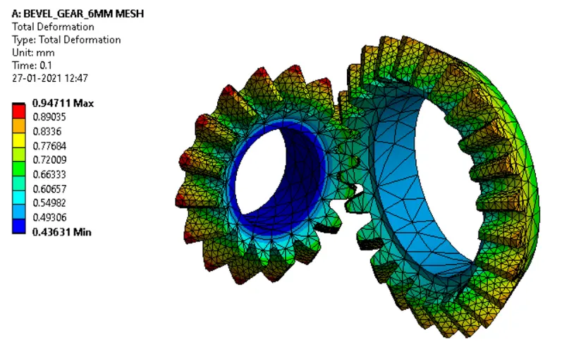
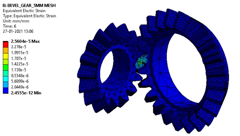
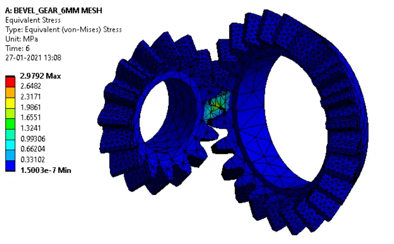
CASE-2: MESH SIZE-6 mm:
TOTAL DEFROMATION:
EQUIVALENT ELASTIC STRAIN:
EQUIVALENT STRESS:
CONCLUSIONS:
- A grid dependency test on bevel gear using ansys workbench is performed successfully.
- The element size of 5mm and 4mm will give optimum and accurate results but over 4mm the mesh with 5mm is preferred for the simulation because the simulation with 4mm mesh will consume a lot of computing efforts and time.