Week 3 Sheet metal Bending challenge
Aim:
- To perform sheet metal bending simulation on aluminum alloy, Copper alloy, and magnesium alloy and comparing the results obtained from the three simulations.
- To perform the simulation for two different values of the coefficient of friction and comparing the results.
- To perform sheet metal bending simulation on aluminum alloy by refining mesh and comparing the simulation results that are obtained from the simulation of the unrefined mesh model.
Procedure:
- Open ansys workbench
- Create a new project.
- Drag and drop a new static structural standalone system into the workspace.
- Rename it as sheet metal bending.
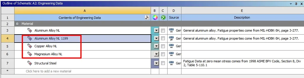
- Now open engineering data and add Aluminium Alloy 1199, Copper Alloy NL, and Magnesium Alloy NL from general non-linear materials.
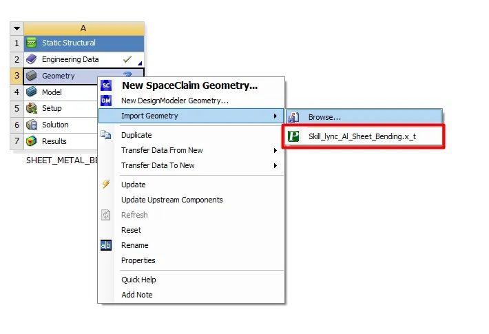
- Now right-clicking on geometry import the geometry.
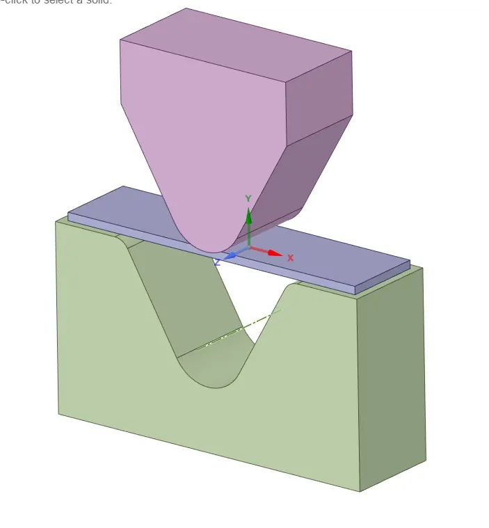
- Now close the space claim and update the project.
- Open ansys mechanical.
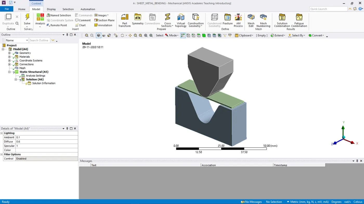
- Now rename the components as required and assign aluminum 1199 for sheet.
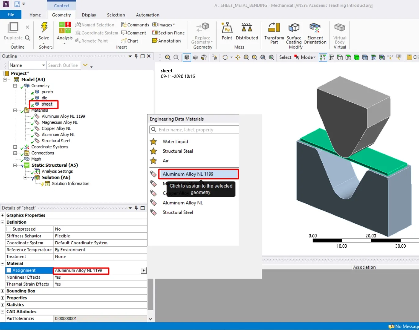
- Properties of aluminum 1199 as below.
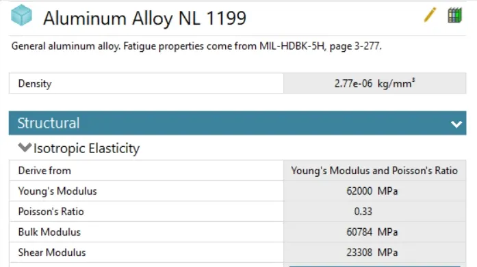
- Repeat the simulation with copper alloy and magnesium alloy those material properties are given below.
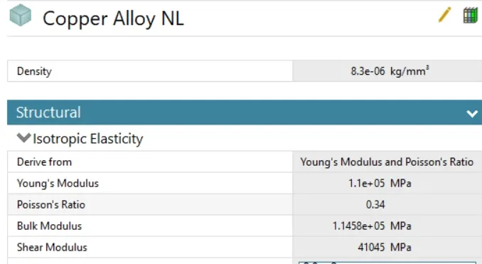

- Now delete the contacts that are automatically created by ansys.
- Create contacts manually.
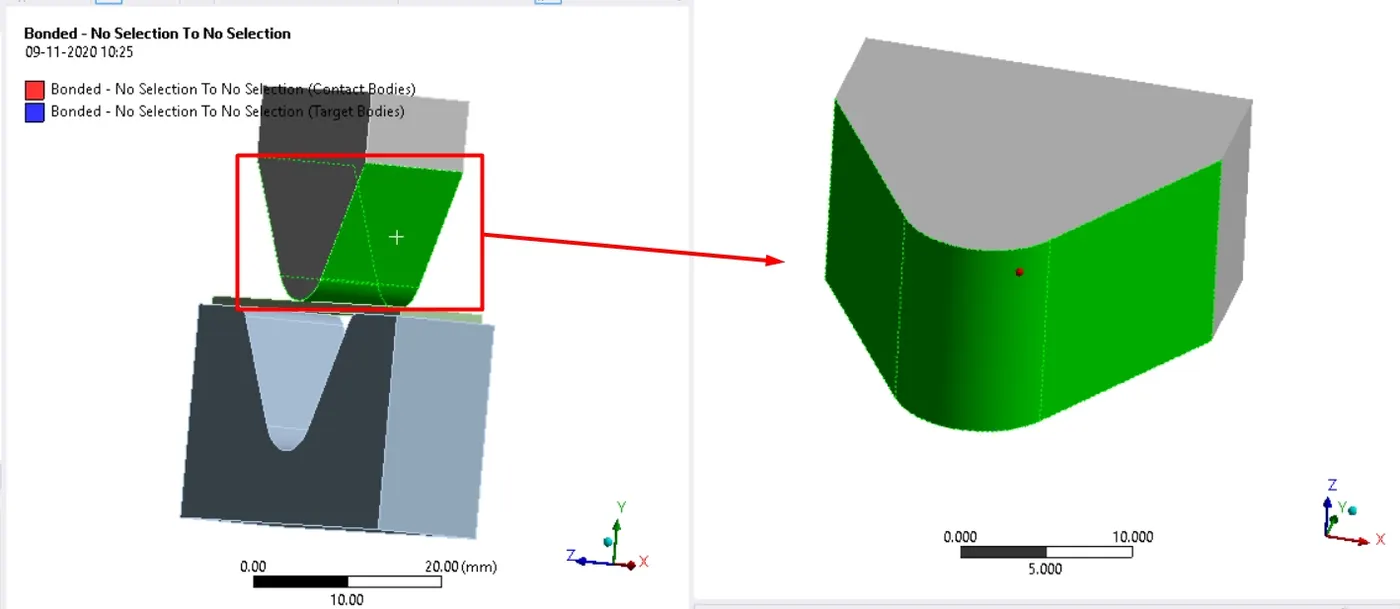
- While simulating there is a contact between the punch and the sheet surface so create the contact between the punch and sheet surface as below.
 .
.
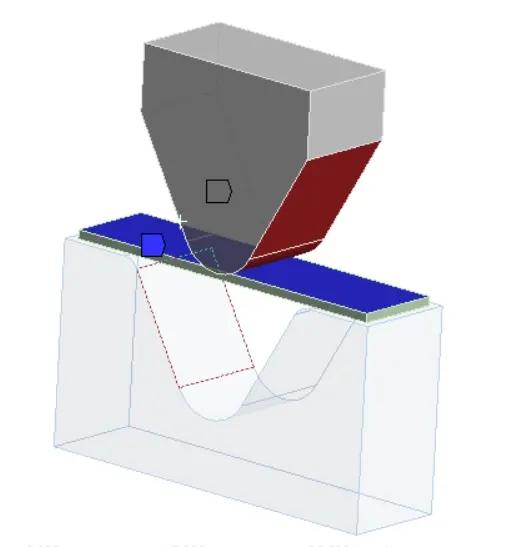
- The surfaces of the punch in the above image are in contact with the sheet under simulation so assign the three surfaces of punch to the contact surface and the sheet surface to which the punch is in contact assign it as target surface. Create contact as below.
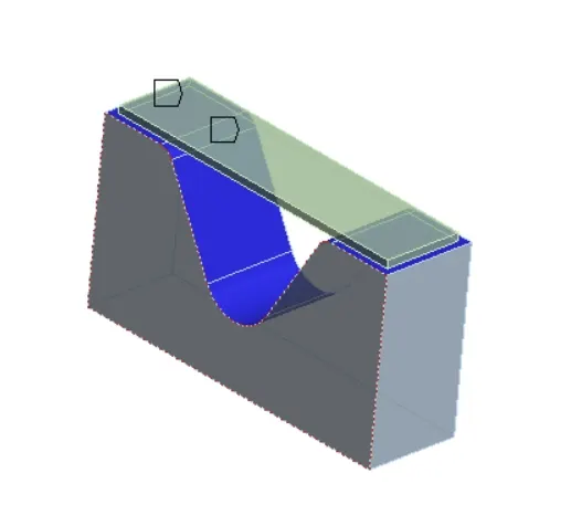
- Now the lower surface of the sheet and the inner surface of the die are in contact create a manual contact region between them as below.
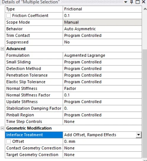
- Now select both the contact and change contact type to frictional and give the coefficient of friction for case 1 as 0.10 and for case 2 as 0.19 change the behavior to auto asymmetric formulation to augmented Lagrange update normal stiffness by a factor of 0.1 and change interface treatment to add offset, ramped effects.
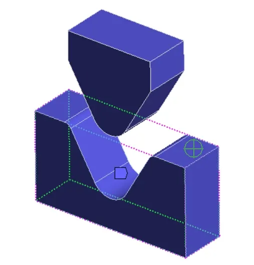
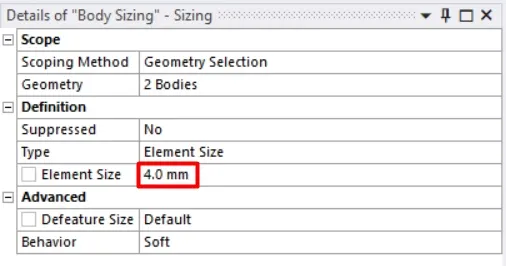
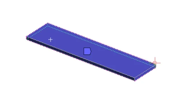
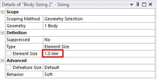
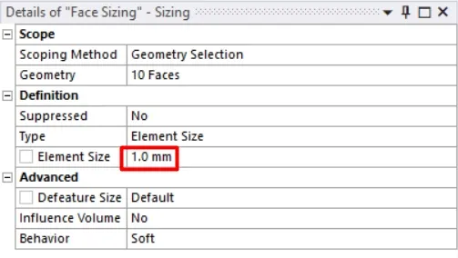
- Now mesh the geometry, mesh the punch and die with an element length of 4mm and sheet with an element length of 1mm and refine the mesh of contact surfaces with 1mm and repeat the simulation by refining the mesh to further better quality and compare results.

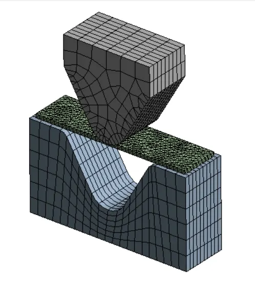
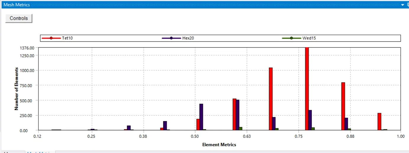
- The above chart shows the mesh metrics that mean the quality of the mesh and the type of elements present in the model and the number of elements present.
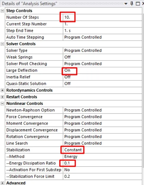
- Now change the analysis settings change the number of steps to 10 and turn on large deflection and under nonlinear controls turn on stabilization and change energy dissipation ratio to 0.1
- Now apply displacements for punch die and sheet in tabular data.
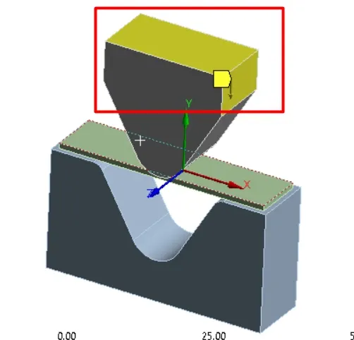
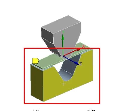
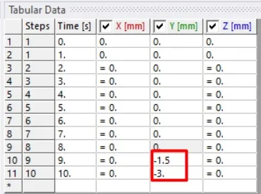
- During sheet metal bending the punch progresses towards the sheet in a downward direction so apply displacement in the y-direction to the surfaces indicated in the above picture in tabular data.
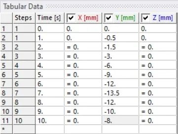
- The punch once progresses towards the sheet it bends the sheet and it returns to its original state we can observe the displacement of punch in the above tabular data.
- The sheet remains in position along Z-direction hence it is fixed in the z-axis.
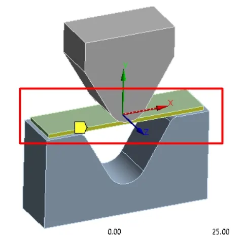
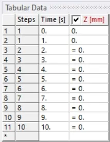
- The die remains in position until bending complete and it retains after bending. The displacement of die is given in tabular data.
- As we can see that setting up the simulation is very much complicated so to reduce the setup time and to avoid confusion create a parameter set for the simulation to find the required results for the three different materials and two different values of coefficient of friction and mesh refinement.
- First, simulate by creating a material parameter set.
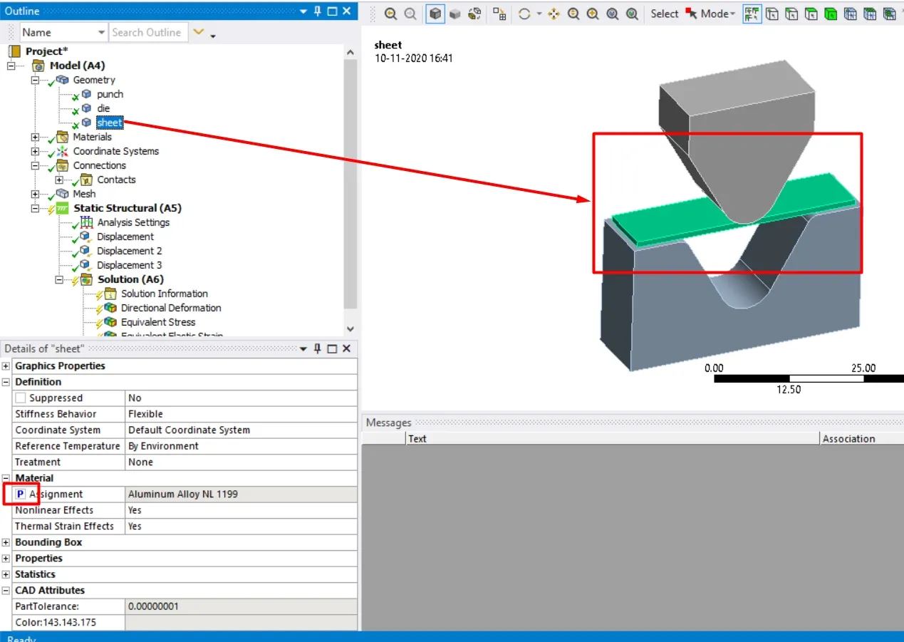
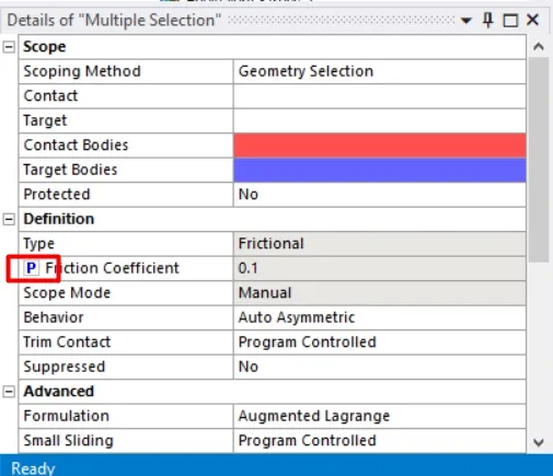
- To create a material parameter set go to geometry and select the sheet geometry mark parametric on the assignment tab as below.
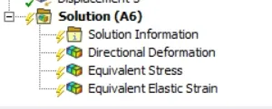
- Now insert the required outputs from the simulation. Equivalent stress, Equivalent elastic strain, and Total Deformation in the Y direction. Insert them into the parameter set.
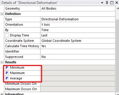
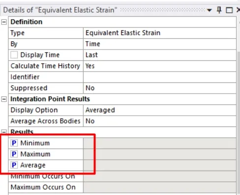
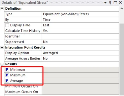
- Simulate to obtain results.
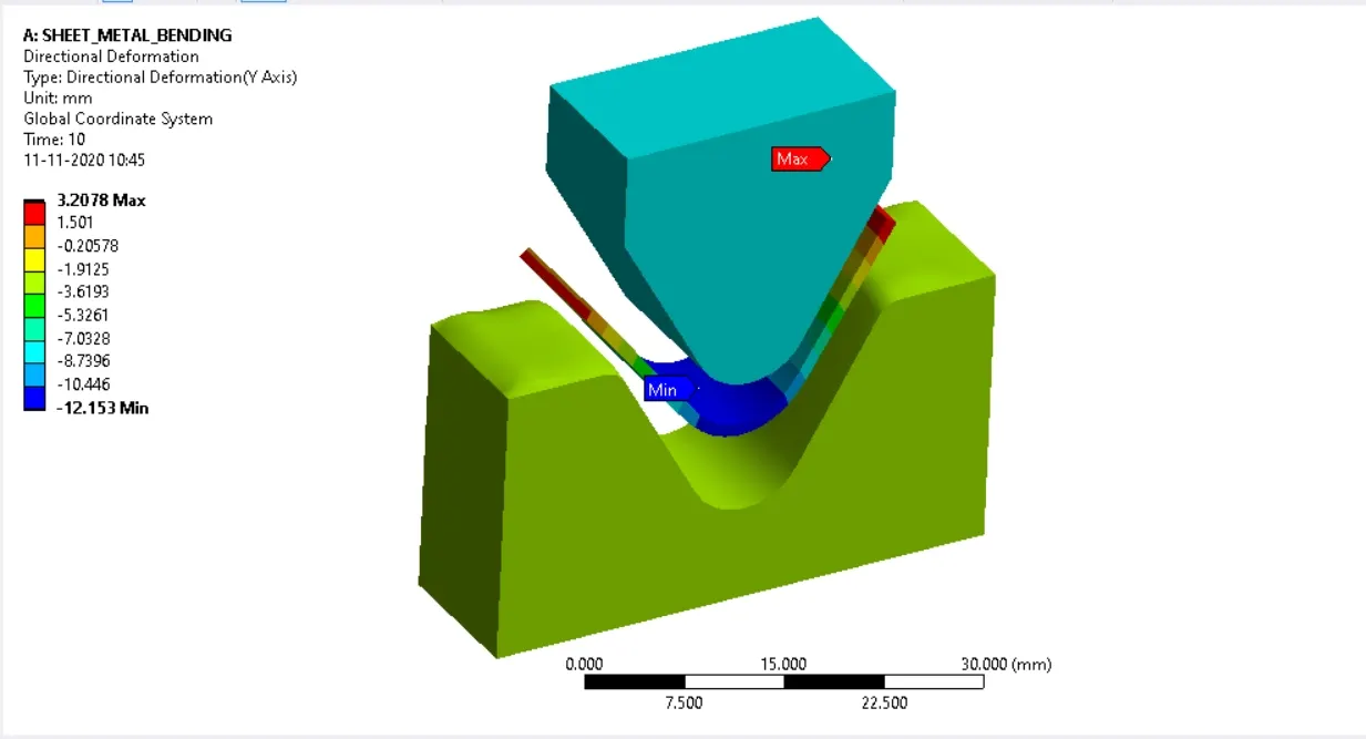
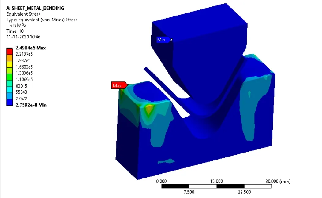
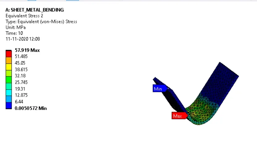
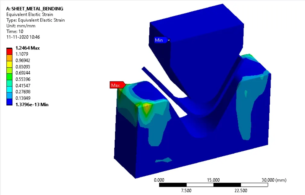
- The results obtained in ansys mechanical are related to aluminum 1199 NL.
DIRECTIONAL DEFROMATION (Y-DIRECTION):
EQUIVALENT STRESS:
EQUIVALENT STRESS IN SHEET:
EQUIVALENT ELASTIC STRAIN:
CASE-1:
- Now got to the parameter set in the workbench and assign different materials.
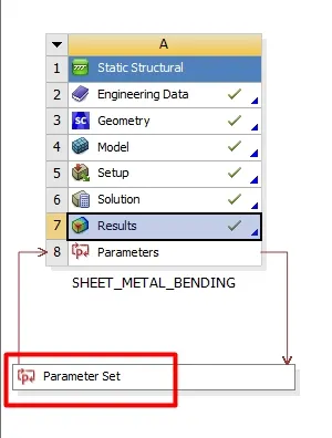
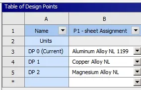
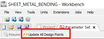
- Click on update all design points to obtain results.
CASE-1 RESULTS:
| SL.NO | MATERIAL | DIRECTIONAL DEFORMATION | EQUIVALENT STRESS IN SHEET | EQUIVALENT STRAIN |
| 1 | ALUMINIUM ALLOY NL 1199 | 2.207 mm. | 57.82 | 1.2464 |
| 2 | MAGNESIUM ALLOY NL | 2.8054 mm. | 118.19 | 1.0463 |
| 3 | COPPER ALLOY NL | 1.4857 mm. | 77.038 | 0.86954 |
CASE-2 & CASE-3:
- Now create a parameter set for the coefficient of friction and open workbench and open parameter.
- Give the value of the coefficient of friction of 0.19 for design point 0 as below.
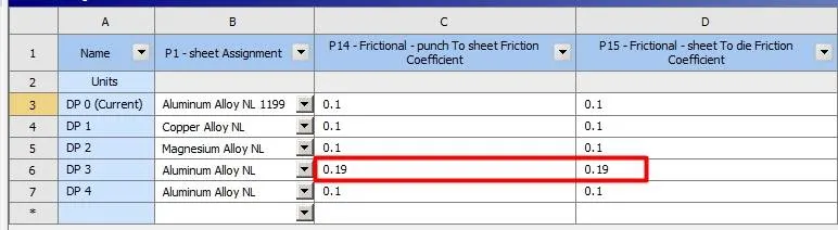
- Now click on update selected design point to obtain results.
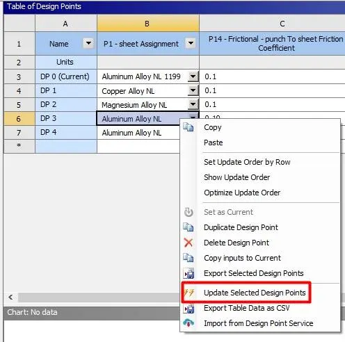
- Now for case-3 simulation create a parameter set for the element size of the plate.
- Refine the mesh to a lower value than the previous simulation makes sure that the element limit doesn't exceed the academic version of ansys.
- Update the selected design point to obtain the results.
CASE-2 & CASE-3 RESULTS:
| SIMULATION CASES & RESULT | RESULTS AT COEFFICIENT OF FRICTION (0.19) FOR ALUMINIUM ALLOY | RESULTS AT ELEMENT SIZE ON SHEET AS 0.75 AND MATERIAL AS ALUMINUM ALLOY |
| EQUIVALENT STRESS | 98144.72 MPa | 183297.10 MPa |
| EQUIVALENT ELASTIC STRAIN | 0.4910 | 0.9173 |
| EQUIVALENT STRESS IN PLATE | 116.062 MPa | 117.959 MPa |
| DIRECTIONAL DEFORMATION | 2.4419 mm | 2.3098 mm |
CONCLUSIONS:
- From the above results tables for case-1, case-2, and case-3, we can say that the equivalent stress in the sheet for aluminum alloy 1199 is less compared to case-2 and case-3. And it is also less compared to other non-linear alloys given.
- The directional deformation and for the copper alloy is less compared to all the other three cases. And elastic strain for the copper alloy is less than all the other given alloy materials.
- As the mesh size changes the value of equivalent stress is increased thus we can say that the accuracy of the solution depends on mesh size.
- The value of the coefficient of friction also affects the results as we can see that the results in case-1 and case 2 and 3 are much different.
- The yield strength and young modulus and tangent modulus also affect the results as we can see the results of aluminum alloy 1199 which has less yield strength and tangent modulus value than aluminium alloy NL thus the equivalent stress in case of aluminum alloy 1199 is less compared to aluminum alloy.