Week 8 - Challenge 1 - Draft Analysis on a Fan Cover
AIM: To perform a draft analysis on the given fan cover model.
OBJECTIVE:
- To check for the continuity of the given surface.
- To create a tooling axis.
- To perform draft analysis along the created the tooling axis.
Checking for surface discontinuties
Input class A surface should be checked for any surface discontinuties.
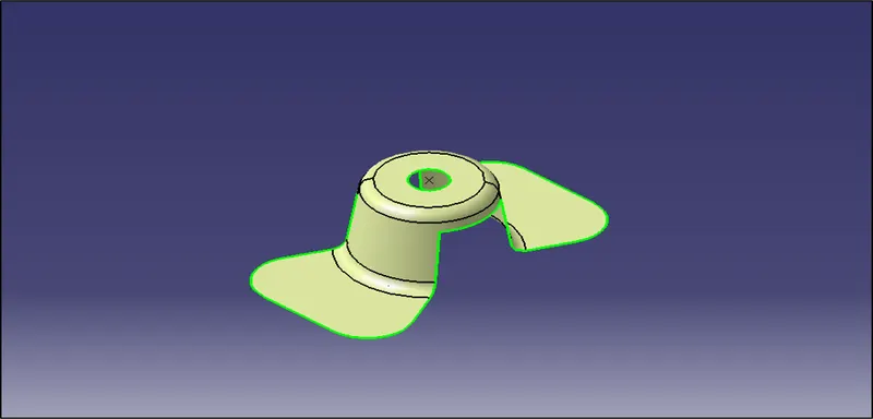
| Fig 1: Class A surface of fan cover |
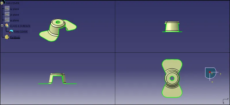
| Fig 2: Surface discontinuity check in different directions |
Free edges or boundaries are highlighted in green color. It is clear from figure 2 that the class A surface doesn't have any surface discontinuity.
TOOLING AXIS
Tooling axis is the direction in which core and cavity seperation happens. Figure 3 shows the dummy tooling created in Z direction.
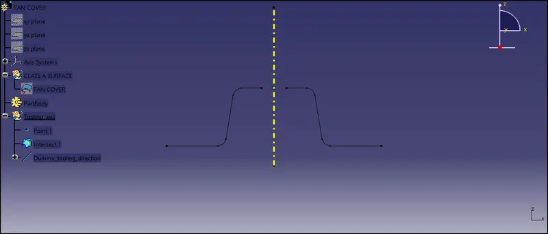
| Fig 3: Dummy tooling axis |
An intersecting profile between Z-X plane and class A surface is created as shown in figure 3, and a bisecting line is created along X direction as shown in figure 4. This procedure is repeated for Y direction.
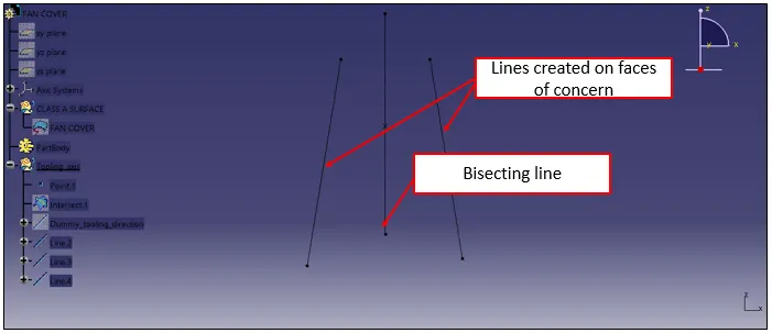
| Fig 4: Bisecting line between faces of concern |
A bisection line between bisecting lines created in X and Y direction is created which is the actual tooling axis along which the core and cavity seperates. Tooling axis is shown in figure 5.
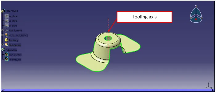
| Fig 5: Tooling axis |
DRAFT ANALYSIS
Draft on a component is provided for the easy ejection of the manufactured part from mold. Green colored component shown in figure 6 requires minimum ejection force as compared to red colored component. Because the green colored component has a draft.
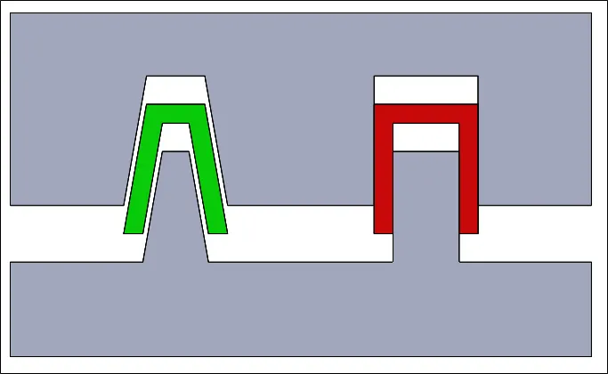
| Fig 6: Part with draft (green) and part without draft (red) |
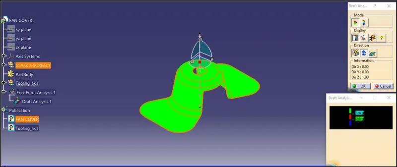
| Fig 7: Draft analysis on fan cover |
It can be seen from figure 7 that a draft analysis has been performed on fan cover and all the faces are above 3 degrees value.
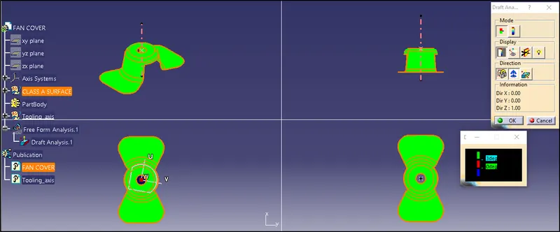
| Fig 8: Draft analysis shown in different views |
CONCLUSION
A draft analysis on fan cover is performed by defining a proper tooling axis.