Week 8 - Challenge 3 - Switch Bezel Design
AIM: To create the switch bezel plasctic component using the given class A surface.
OBJECTIVE:
- To create a tooling axis and perform draft analysis on the given class A surface.
- To create a class B surface.
- To create a class C surface.
- To join all the three surfaces to each other and create a closed surface.
- To create a 3D part model from the surface model and perform draft analysis.
CLASS A SURFACE
A tooling axis is created with the help of bisecting lines and a draft analysis is performed on class A surface.
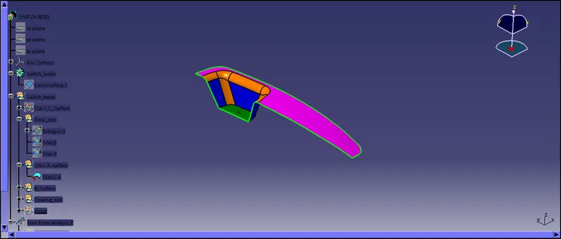
| Fig 1: Class A surface |
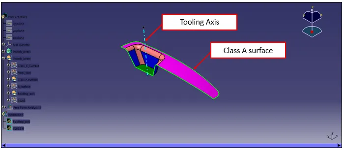
| Fig 2: Class A surface with tooling axis |
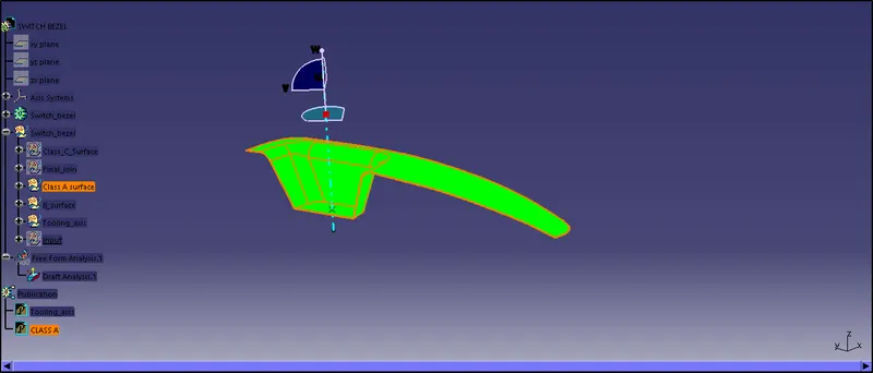
| Fig 3: Surface A draft analysis |
CLASS B SURFACE
Class B surface is the engineering surface on which features like boss, ribs are provided. It is formed by offsetting the class A surface by a distance equal to the thickness of the product.
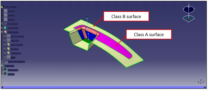
| Fig 4: Class B surface |
CLASS C SURFACE
Class C surface joins class A surface and class B surface.
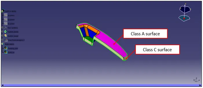
| Fig 5: Class C surface along with class A surface |
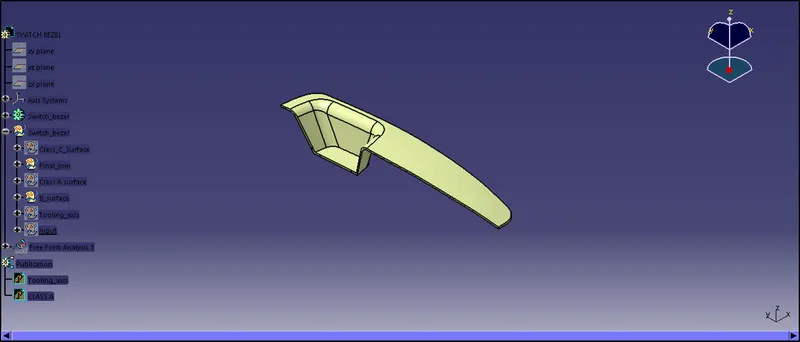
| Fig 6: Surface model of switch bezel |
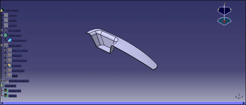
| Fig 7: Part model of switch bezel |
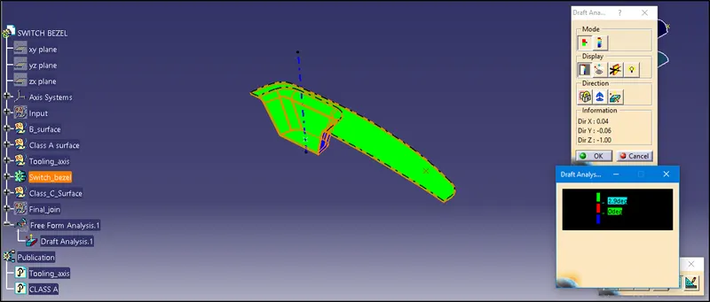
| Fig 8: Draft analysis of part model |
It can be seen from figure 8 that for the given tooling direction draft is above 3 degrees.

| Fig 9: Draft analysis of part model in different orientations |
CONCLUSION
Hence a switch bezel plastic component is created with the help of class A surface provided. A draft analysis is performed as shown in figure 8 and 9, which shows that for the given tooling direction the components draft is above 3 degrees which is the acceptable limit.