Wiring harness design in CATIA V5 - 3D modeling Week 2 Challlenge
AIM: To download the connector and mounting clip from open source and assign the necessary characters
OBJECTIVE:
- To download the connector and clip from open source.
- To create bundle entry point and connector contact point.
- To define the character of connector and clip.
- To assemble the mounting clip and connector.
CONNECTOR #1-Deutsch DT06 – 08SA
- Connector and mounting clips are downloaded from te.com in IGES format and imported into CATIA.
- After importing the model, it is necessary to identify the mating face and terminating face of the connector.
- Connector connection point and bundle connection point are created on mating face and terminating face respectively.
- An axis system at the connector connection point is created such that Y axis points towards the mating face and X axis along the locking feature or retention feature on the connector.
- The part is then defined as a connector as shown in figure 6.
- Connector connection point and bundle connection points are defined.
- A mounitng is defined as a mounting equipment and is assigned as a cavity.
- If a mounting clip is to be assembled on a connector, the point is definde as a connector cavity point.
- Connector and mounting clip are assembled using connect electrical device command.
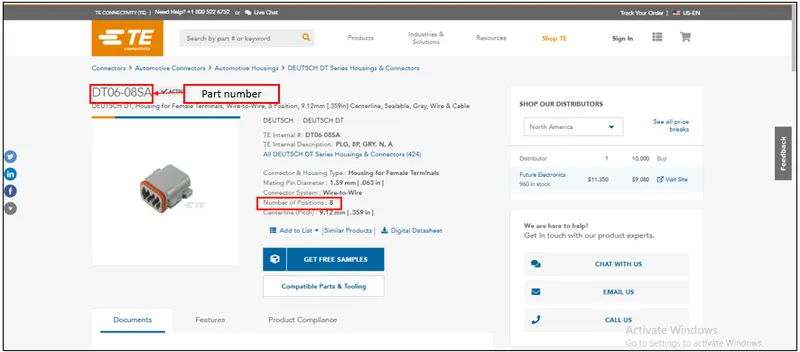
| Fig 1: Te.com website |
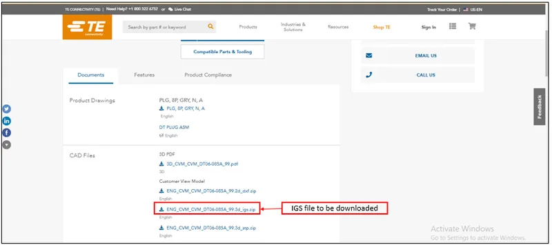
| Fig 2: File format to be downloaded |
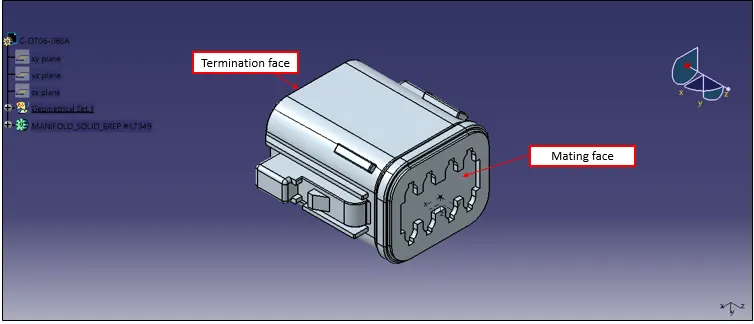
| Fig 3: Downloaded model of DT06-08SA |
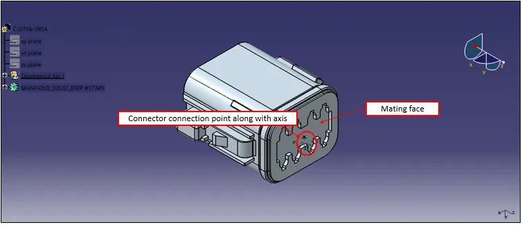
| Fig 4: Connector with connection point |
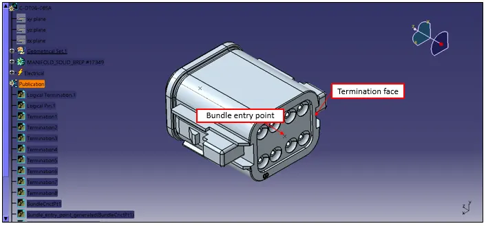
| Fig 5: Connector with bundle entry point |
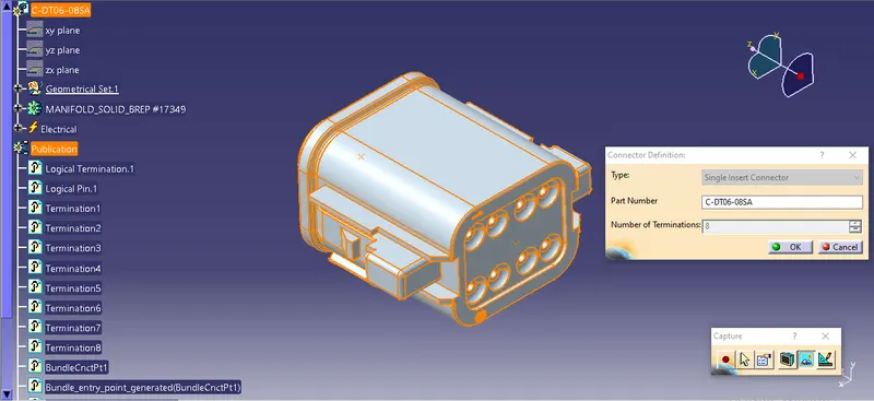
| Fig 6: Defining a connector |
Since the number of positions are 8 in this case number of terminations are 8.
CONNECTOR #2 -Tyco 174357-2 with mounting clip - Tyco 85229-1
The above mentioned procedure is followed along with mounting clip definitions.
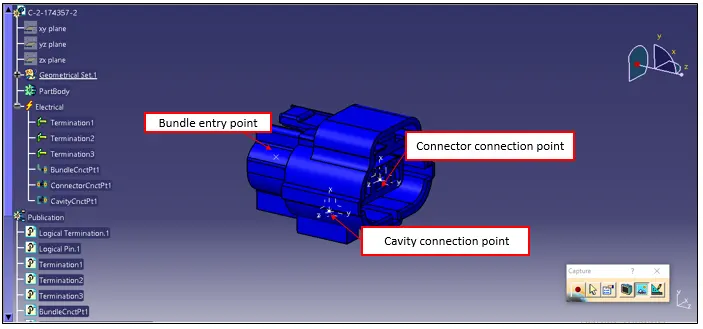
| Fig 7: Connector with necessary properties |
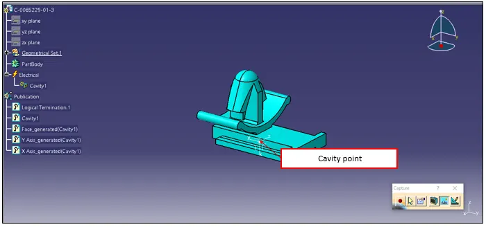
| Fig 8: Mouting clip necessary |
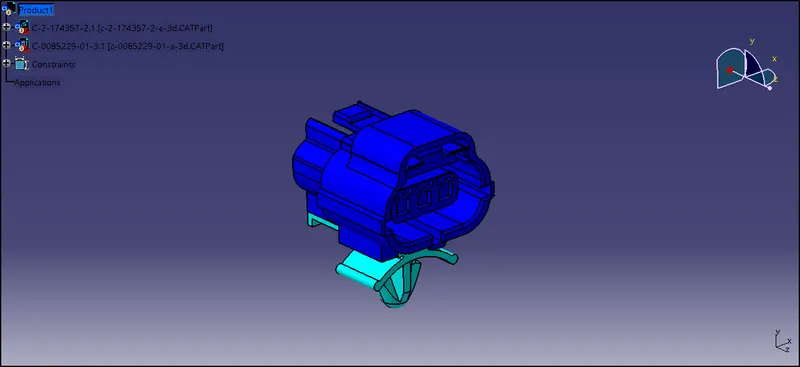
| Fig 9: Connector and mouting clip assembly |
CONCLUSION
Hence a connector is imported into electrical part design and necessary characters are assigned.