Week 11 - Final project
AIM: To develop a door trim panel using given class A surface with the help of given master sections.
OBJECTIVE:
- To join the unconnected surfaces to its respective subparts and import them into assembly workbench.
- To perform draft analysis of the individual component by creating a proper tooling axis for each component.
- To create a solid part model by creating class B and C surface from given class A surface.
- To create appropriate engineering features on the B surface.
INTRODUCTION
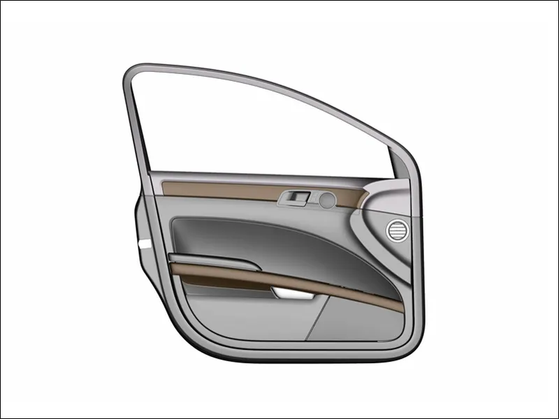
| Fig 1: Typical inner panel of car door (www.fes-aes.de) |
A car door is a complicated module made up of a number of fixed and movable subassemblies and components. Safety, vehicle dynamics, aesthetics, and strength are all important factors to consider while building the door assembly. Apart from the foregoing, door trim should be designed to reduce BSR (buzz, squeak, and rattle) during vehicle operation (Sahoo.M., Langfei. R., et al, 2017 ). Figure 1 shows a typical inner panel of car door.
A car door trim panel has different components and sub assemblies. Four important components developed in this project are listed below and as shown in figure 2.
- Arm rest.
- Lower substrate.
- Lower map pocket.
- Upper map pocket.
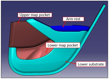
| Fig 2: Lower door trim panel |
An unconnected class A surface along with master sections are provided as shown in figure 3.
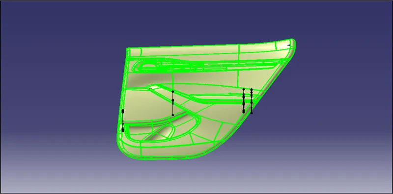
| Fig 3: Input class A surface with master sections |
Above shown class A surface is joined using join command with all appropriate surfaces to its respective components as shown in figure 4.
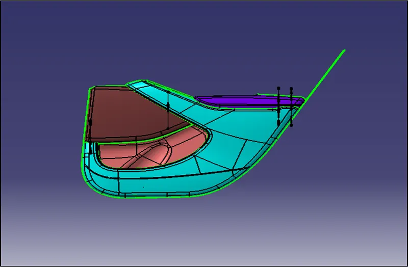
| Fig 4: Joined surfaces |
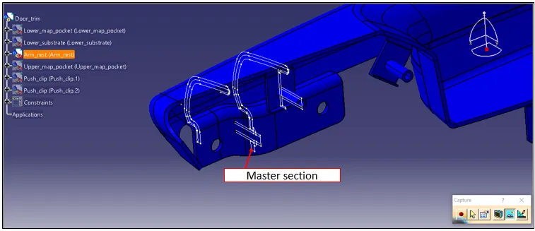
Figure 5 shows the different engineering features to be created in the B side according to master section given.
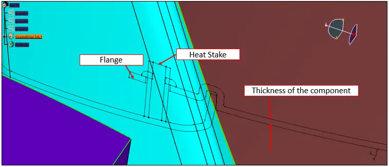
| Fig 5: Illustration of master section |
Given surface data is imported into assembly workbench as shown in figure 6. A top down approach is used in this study.
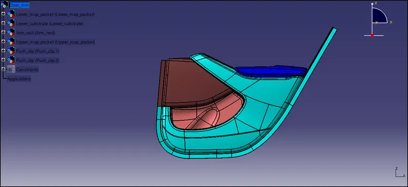
| Fig 6: Surface data in assembly work bench |
DRAFT ANALYSIS OF CLASS A SURFACE OF INDIVIDUAL COMPONENTS
Draft analysis is performed on the component to analyse whether the component is provided with the sufficient draft, to make it east to remove from the mold while ejecting the component. Figure 7 shows the component with and without draft. Tooling axis the direction along which core and cavity seperates.
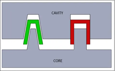
| Fig 7: Component with draft and without draft |
Arm Rest
Figure 8 shows the class A surface with main tooling axis and side core axis.
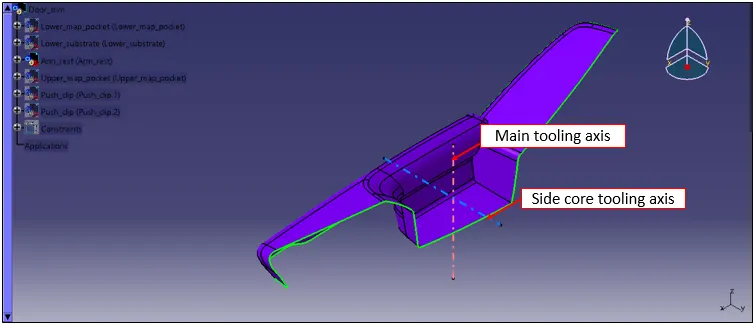
| Fig 8: Arm rest class A surface with tooling axis |
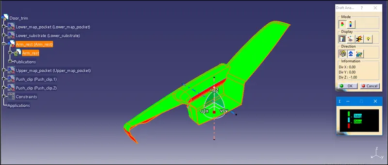
| Fig 9: Draft analysis of arm rest along main tooling axis |
Surfaces in green color are cleared by main tooling axis as shown in figure 9. For the areas in red we need to consider a side core axis as shown in figure 10.
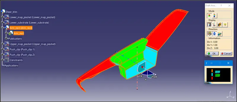
| Fig 10: Draft analysis of arm rest along side core axis |
Lower Substrate
Figure 11 shows the class A surface of lower substrate and as shown in figure 12 the tooling axis clears the lower substrate.
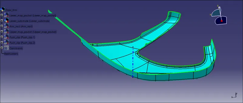
| Fig 11: Lower substrate with main tooling axis |
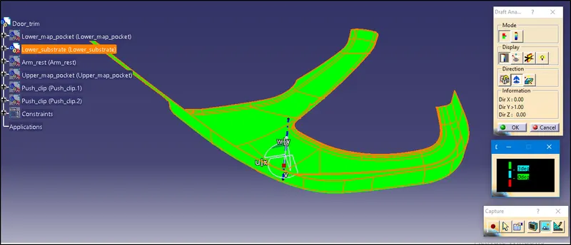
| Fig 12: Lower substrate draft analysis |
Lower Map Pocket
Figure 13 shows the class A surface of lower map pocket with tooling axis. As shown in figure 14 the tooling axis clears all the concerned surfaces, area highlighted in red has a -10 deg draft which needs to be escalated to the surface design team.
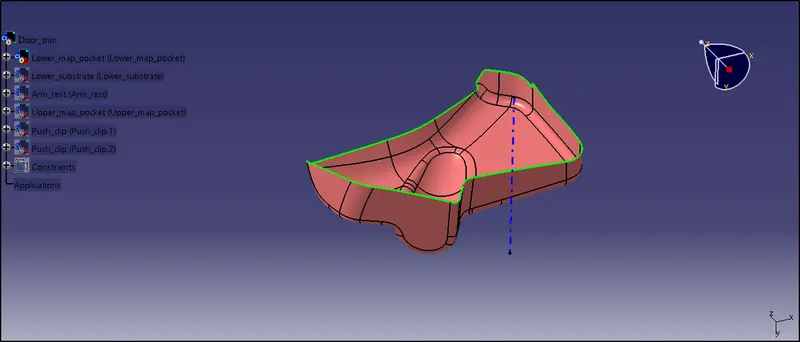
| Fig 13: Lower map pocket class A surface with tooling axis |
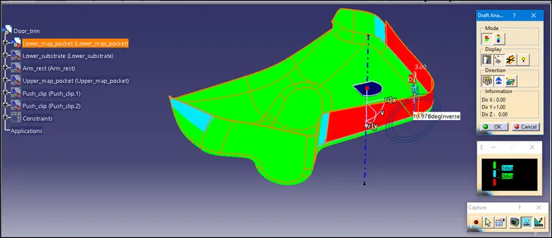
| Fig 14: Lower map pocket class A draft analysis |
Upper Map Pocket
Figure 15 shows the upper map pocket with tooling axis. As shown in figure 16 the surface has sufficient draft along the tooling axis which is 3 degree in this project.
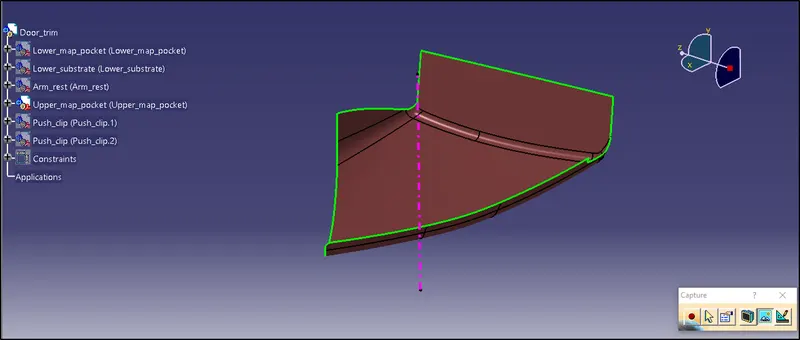
| Fig 15: Upper map pocket with tooling axis |
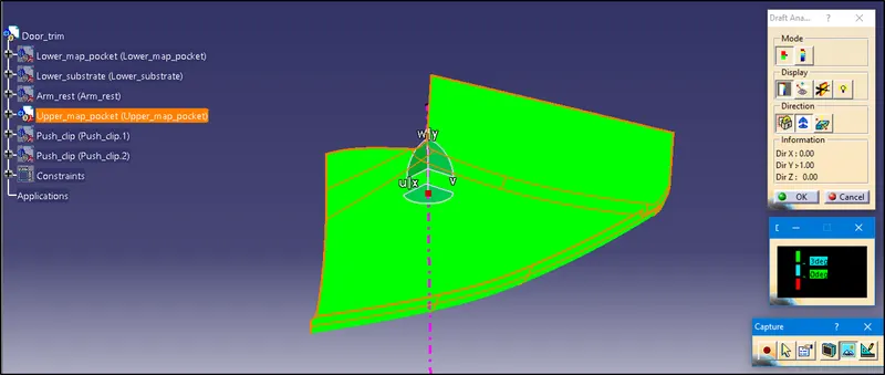
| Fig 16: Upper map pocket draft analysis |
CREATION OF SOLID MODEL WITH ENGINEERING FEATURES
Arm Rest
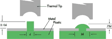
As the name suggests arm rest is used as an aesthetic feature and its sole purpose is to rest the arm and have power window buttons. Figure 17 shows the surface model of the arm rest and figure 18 shows the solid model of the arm rest with engineering features. Thermal staking provides an alternative to welding when the two parts consist of dissimilar materials which cannot be welded or when simple mechanical retention of one part relative to another is adequate.
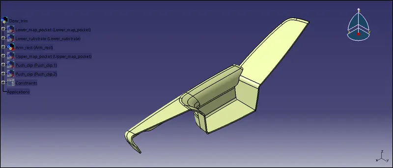
| Fig 17: Closed surface model of arm rest |
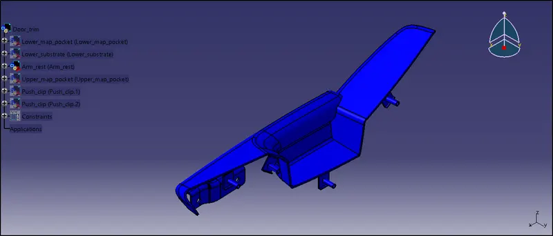
| Fig 18: Solid model with engineering features |
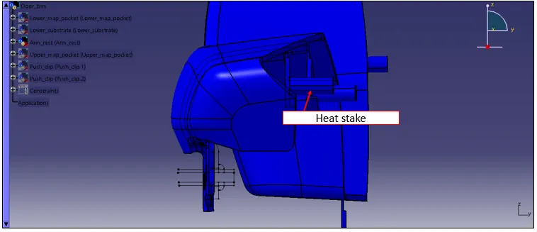
| Fig 19: Arm rest with heat stake |
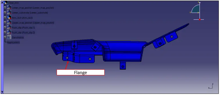
| Fig 20: Arm rest with flange |
| Fig 21: Heat staking |
| Fig 22: Door arm rest master section |
Upper Map Pocket
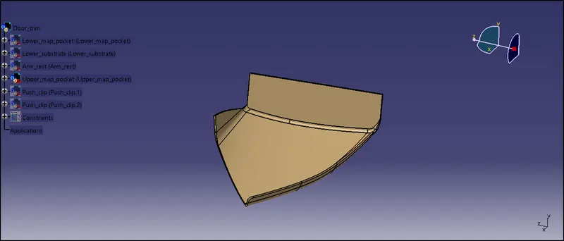
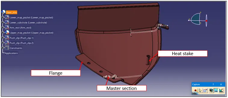
Figure 23 shows the closed surface model of upper map pocket and figure 24 shows the solid model upper map pocket.
| Fig 23: Closed surface model of upper map pocket |
| Fig 24: Solid model of upper map pocket with engineering features |
Lower Map Pocket
Figure 25 shows the closed surface model of lower map pocket and figure 26 shows the solid model of lower map pocket with flanges.
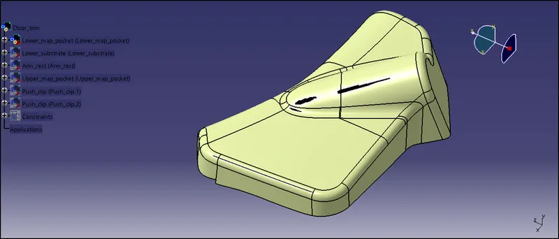
| Fig 25: Closed surface model of lower map pocket |
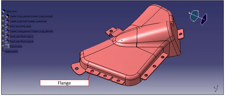
| Fig 26: Solid model of lower map pocket with flanges |
Lower Substrate
Figure 27 shows the closed surface model of the lower substrate and figure 28 shows the solid model of lower substrate.
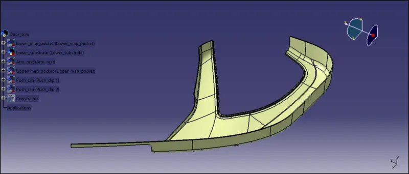
| Fig 27: Closed surface model of lower substrate |
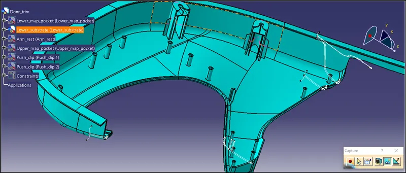
| Fig 28: Solid model of lower substrate with engieering features |
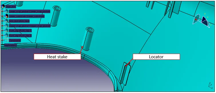
| Fig 29: Lower substrate with heat stake and locator |
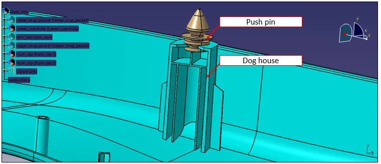
| Fig 30: Lower substrate with dog house and push pin |
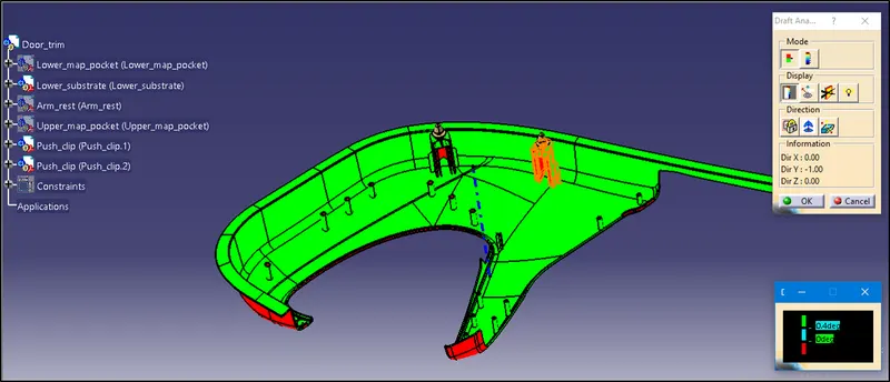
| Fig 31: Draft analysis of lower substrate engineering features |
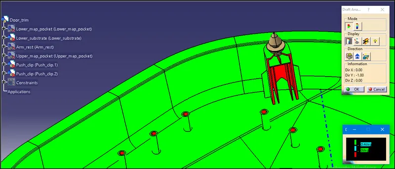
| Fig 32: Lower substrate draft analysis of dog house and heat stake |
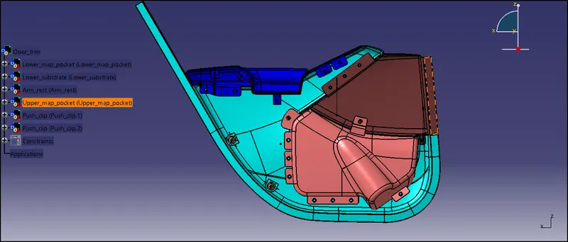
| Fig 33: Door trim with engineering features |
CONCLUSION
A door trim panel using given class A surface with the help of given master sections has been developed by following steps
- To join the unconnected surfaces to its respective subparts and import them into assembly workbench.
- To perform draft analysis of the individual component by creating a proper tooling axis for each component.
- To create a solid part model by creating class B and C surface from given class A surface.
- To create appropriate engineering features on the B surface.