Week 11- Assembly Workbench
AIM: To create the assemblies and draft the individual parts and assemblies.
QUICK RETURN MECHANISM
A quick return mechanism is a device that generates a reciprocating motion in which the return stroke takes less time than the forward stroke. It uses a system of links with three turning pairs and a sliding pair to be driven by a circular motion source (usually a motor of some sort). With an offset crank, a quick-return mechanism is a subclass of a slider-crank linkage.
An assembly is created by creating individual components with the help of given drawings.
Rocker
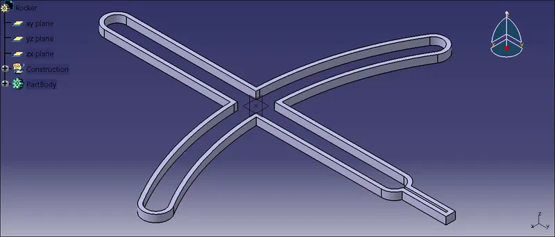
| Fig 1 : Rocker part body |
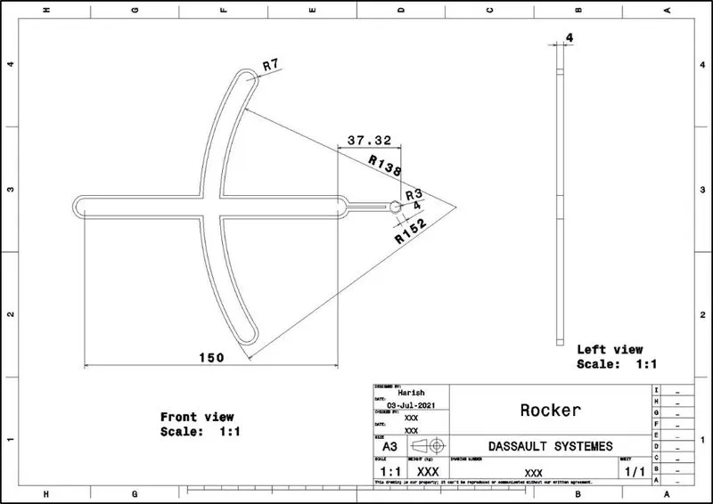
| Fig 2: Rocker drafting |
Rocker arm
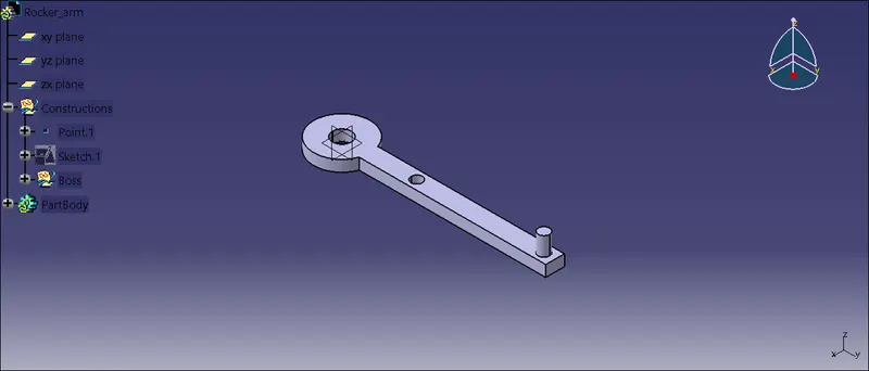
| Fig 3 : Rocker part body |
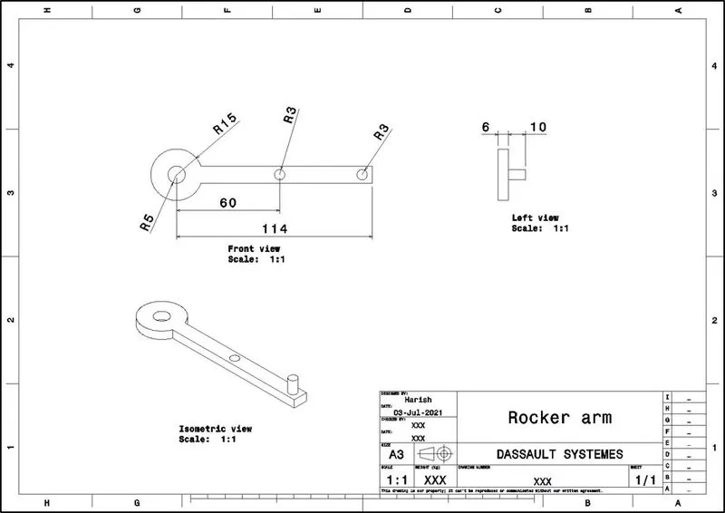
| Fig 4: Rocker arm drafting |
Slider
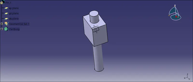
| Fig 5: Slider |
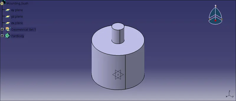
| Fig 6: Mounting bush |
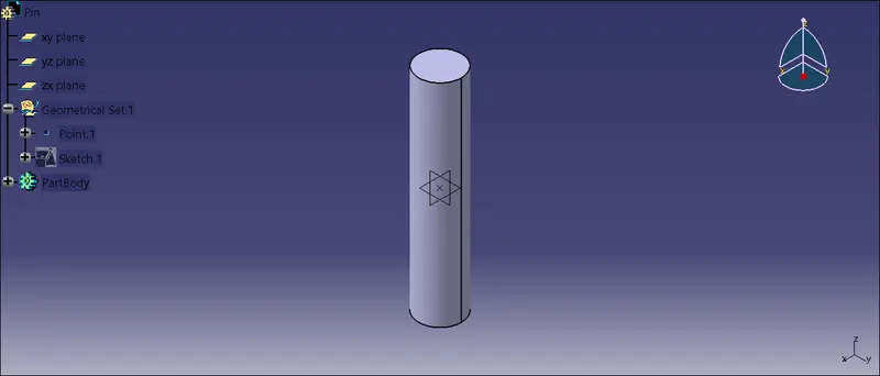
| Fig 7: Pin |
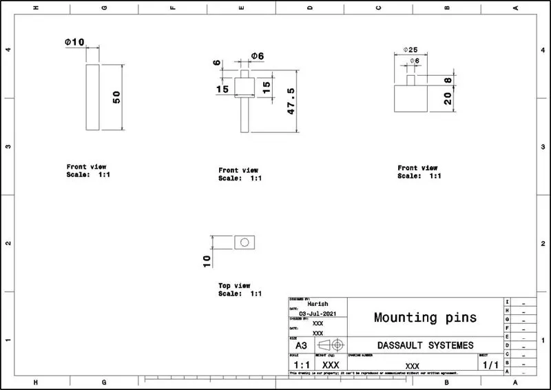
| Fig 8: Bush, pin and slider drafting |
Assembly
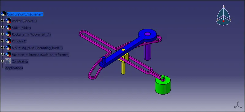
| Fig 9: Quick return mechanism assembly |
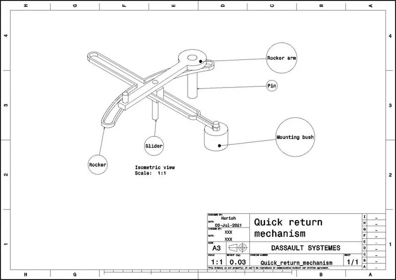
| Fig 10: Quick return mechanism drafting |
CONSTANT VELOCITY JOINT
Allows a drive shaft to convey power across a varied angle while maintaining a steady rotating speed with minimal friction or play. They're mostly found in front-wheel-drive cars. CV joints are commonly used at the ends of rear axle halfshafts and are increasingly being used on the drive shaft in modern rear wheel drive cars with independent rear suspension.
An assembly is created by creating individual components with the help of given drawings.
Main body
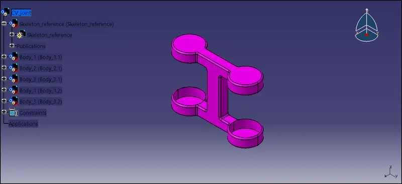
| Fig 11: Main body in assembly environment |
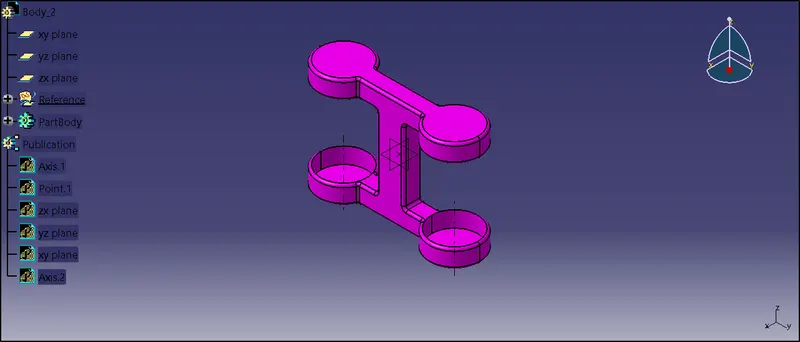
| Fig 12: Main body in part environment |
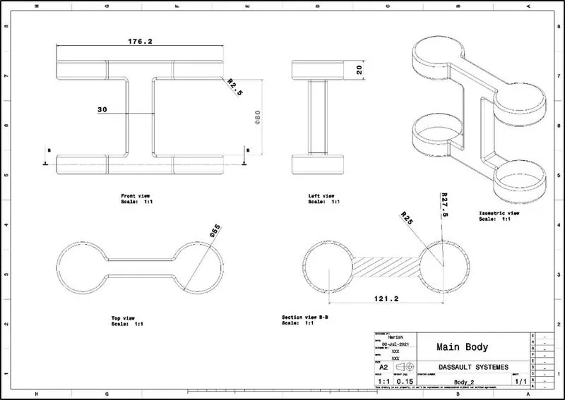
| Fig 13: Drafting of main body |
Joint
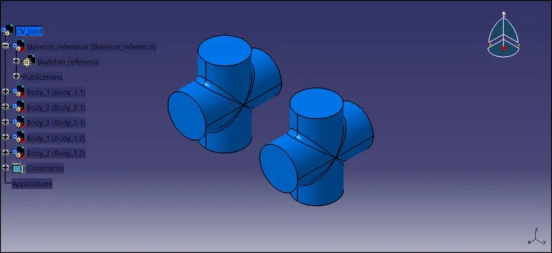
| Fig 14: Joint in assembly environment |
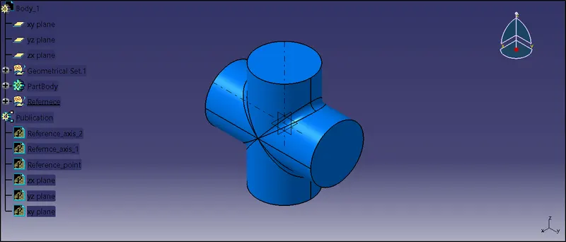
| Fig 15: Joint in part environment |
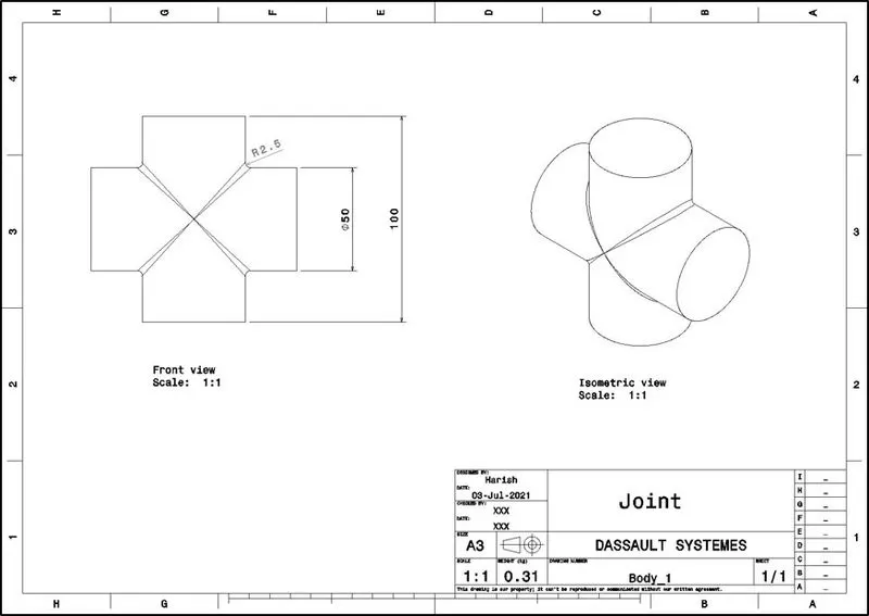
| Fig 16: Joint drafting |
Rocker
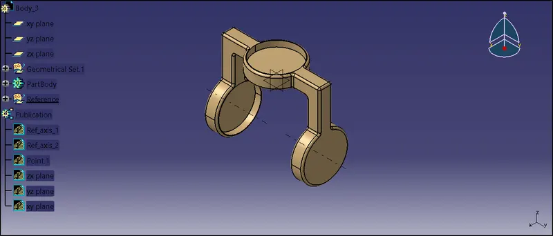
| Fig 17: Rocker in part environment |
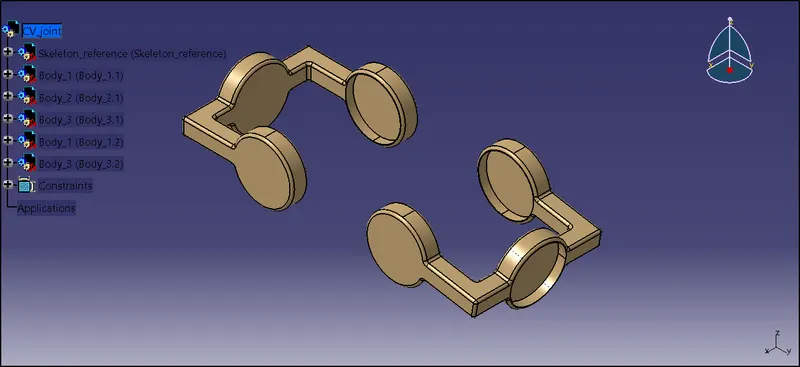
| Fig 18: Rocker in assembly environment |
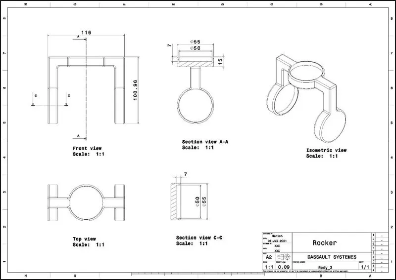
| Fig 19: Rocker drafting |
Assembly
Individual parts are imported into assembly environment as shown in figure. A skeleton part or a refernce part is created.
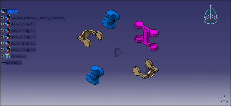
| Fig 20: Parts imported in assembly environment |
Main body is constrained using coincidence with the skeleton part created.
Constraint used
- Coincidence.
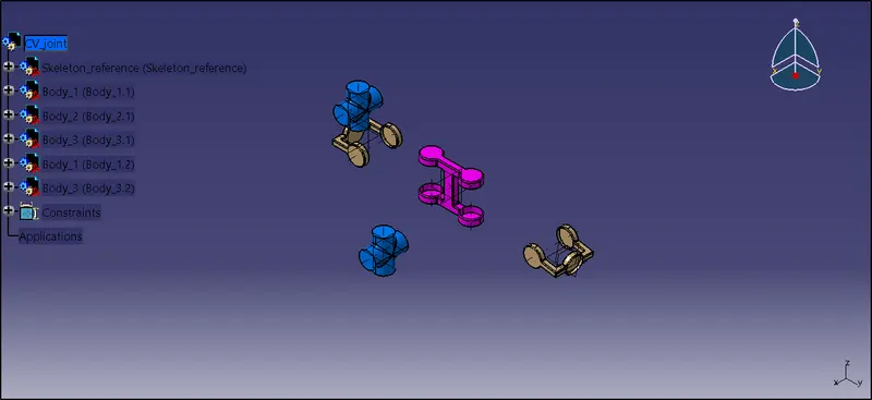
| Fig 21: Constraining skeleton part and main body |
Joint is constrained onto mainbody using
- Angle constraint.
- Coinciding the axis of main body and joint.
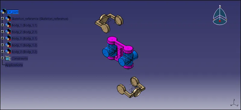
| Fig 22: Constraining main body with joint |
Final assembly is created by assembling the rocker onto previously created assembly using the coincide constraint.
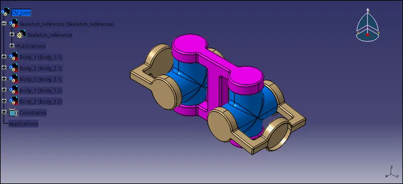
| Fig 23: Final assembly |
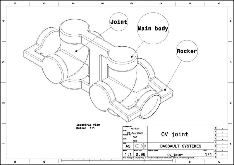
| Fig 24: Final assembly drafting |