Week-7 Head Impact
Aim:
The Aim of this Challenge is to Create Head impact simulation considering three different Cases.
1. Impact of Pedestrian Headform Over Rigid Body.
2. Impact of Pedestrian Headform over Deformable Aluminium Hood
3. Impact of Spherical Head Over Rigid Body.
HISTORY:
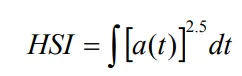
Attempting to Quantify the Possible injury to Human Head is Complex process. There are Various Criteria proposed worldwide in an attempt to quantify the Injury to Head during Impact process. The relationship between the acceleration level & Impulse duration with respect to head injury was first proposed by WSTC Curve.(Wayne State Tolerance Curve). WSTC has been widely criticised due to limited number of data points, faulty instrumentation techiques.The WSTC data was ploted on log log paper by Gadd & Straight line function is obtained which is eventually called as Gadd Severity Index (GSI) or Head Severity Index (HSI).
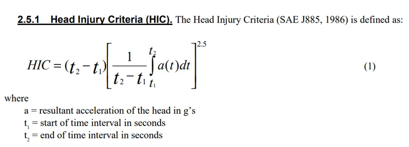
The HIC was defined by NHTSA in 1972, HIC is currently used to access the Head injury potential in automobile Crash Test Dummies. The AIS (Abbreviated Injury Scale) published by American Association for Automotive Medicine was used to provide a basis for comparison of HIC & Chest Deceleration.
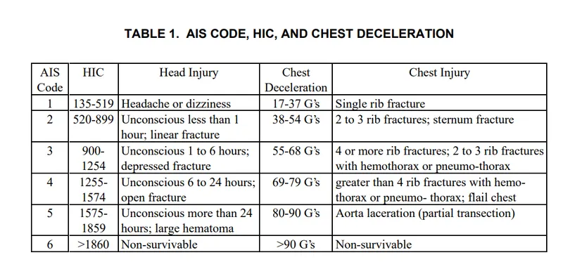
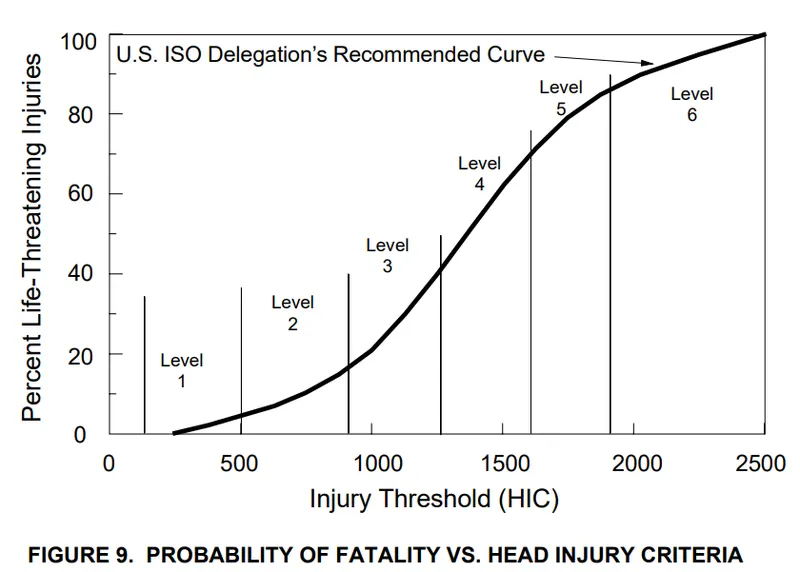
Each Range of Values in HIC is associated with AIS Code. Each Level of AIS Code has a specific probability of life threatening injuries. Lower HIC doesn't gurantee that there are no threat to life, because it also has some probability of life threatening Injuries. Lower HIC Value Only indicates, that the probability of Life threatening Injuries is less and it should be always remembered that there is little possibility of life threatening injuries even with lower HIC. From the above table you can see that HIC value of above 1860 is simply tagged as Non-survivable.
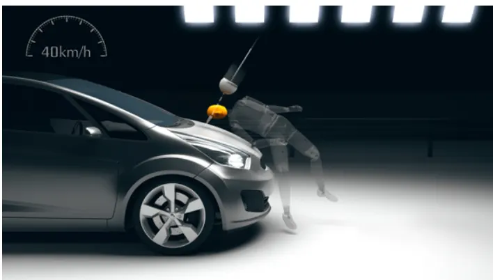
Pedestrian Safety Test Conditions: Euro NCAP uses standardized test to simulate most common Pedestrian Crashes. The Test are done at 40Kmph to represent what is happening in case of impact of pedestrian in City Roads. Regarding Head Impact, the speed of the Headform has to be 40Kmph and the Angle of Impact has to be between 35 to 75 degrees. In this simulation, the Child Headform is used.
Case 1. IMPACT OF PEDESTRIAN HEADFORM WITH RIGIDWALL
The Input file for the Pedestrian Child Headform is provided by regulatory bodies, Hence the Input files should not be Changed. As First step the Transformation is defined in LS DYNA using DEFINE_TRANSFORMATION Card. The Parameters a1, a2 & a3 define the Direction Cosines of the Line passing through the Points a4,a5 &a6. The rotation angle is defined. This transformation will Rotate the Pedestrian Headform at 45 degrees (Anticlockwise) through the line defined by Direction cosines.
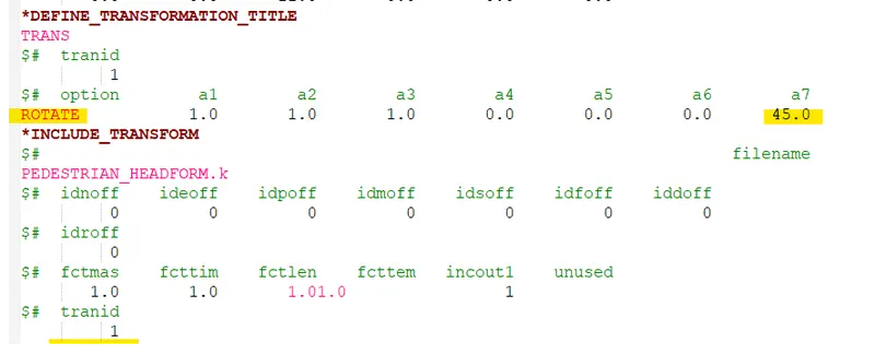
The Transformation is applied to Pedestrian Headform Input file by using INCLUDE_TRANSFORM Card.
Once the Headfoam is oriented, the Node set ID is created & Initial Velocity is defined. In Pedestrian Headform file the Unit system followed is Kg/mm/ms system, hence the same unit convention is followed when writing the Main simulation file. The Impact Velocity of 11mm/ms is specified in Z-direction.

Rigid Wall is created and the Automatic single Surface Contact is specified by creating a part set ID comprising of all the parts of Headfoam. The Termination time is specified as 10ms and the ASCII & Binary outputs like MATSUM, GLSTAT, NODOUT are written for every 0.0013ms.
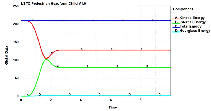
The Energy Plot of Impact of Headform over the Rigid Wall is shown below, As expected the Kinetic Energy of Headform decreases and the Internal Energy Increases during the Impact. The Raise in Internal Energy of Headfoam is 106 Joules.
The Maximum Von-misses Stress Experienced during Impact of Headform over the Rigid Body for Element 3060 is found to be 7Mpa.
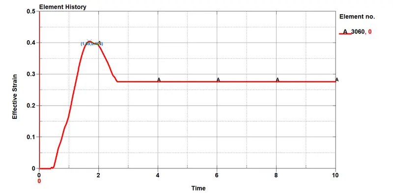
The Highest Effective Strain Experienced by the Element 3060 during the Impat is found out to be 0.41, which is 41%.
The Accelerations experienced by the Node 25679 is Recorded and HIC Calculation is Done. HIC-15 stands for the time interval of 15 Seconds and HIC-36 stands for the time interval of 36 Seconds.
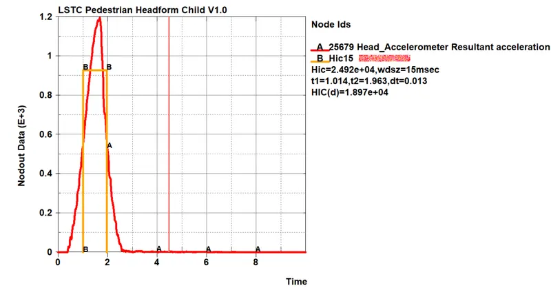
The Head Injury Criteria Calculated to be 24,990 > 1860 and Hence the Impact is tagged as "Unsurvivable". It should be remembered that in real world conditions, the Rigid Wall Doesn't exist.
Case 2. IMPACT OF PEDASTRIAN HEADFORM WITH ALUMINIUM HOOD.
In this Case the Impact of Pedastrian Headforam is simulated with Aluminium Hood. The Aluminium hood is modelled as shell Elements with thickness of 3mm. The Material data is provided in Kg/mm/ms unit system to avoid Errors in simulations.
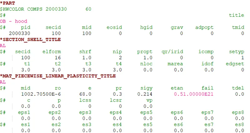
The Head is oriented using "DEFINE_TRANSFORMATION" & "INCLUDE_TRANSFORMATION" option. The Initial Velocity of Headform is specified as below.

The Energy Plot of Headfoam Impact with Aluminium is given below, The Raise in internal energy during impact is 94J. It is important to note that the Internal Energy raise is less in this case compared to previous case. (In previous case the internal energy raise is 106J)
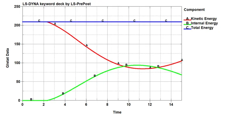
In Previous case, the Peak Internal Energy raise observed in the time interval (Time of impact - Time of Peak Internal Energy) of 1.592ms. In case of Impact with Aluminium hood, The Peak Internal Raise observed in the time interval of 10.157ms. Hence we can infer that the Impulse of force is very less in case of Impact with Aluminium compared to impact with Rigid wall.
The Maximum Stress Experienced by the Element 3060 in Impact with aluminium foil is 3.8Mpa, while in previous case it is around 7Mpa.
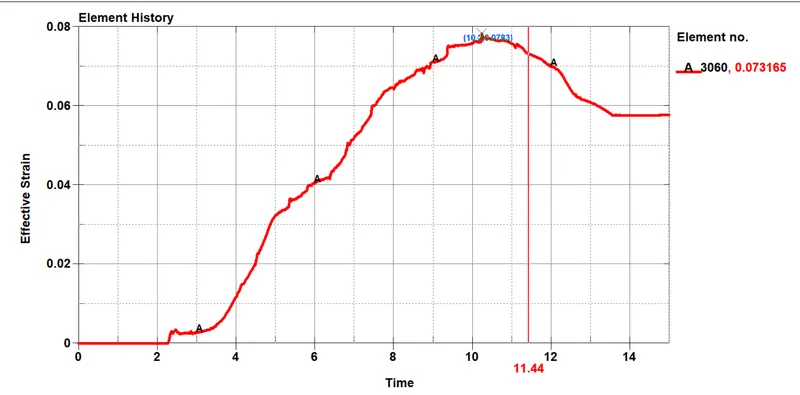
The Maximum Strain experienced by the element 3060 is 0.073 which is 7.2%.
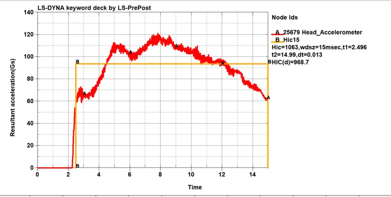
The HIC Calculations as follows, The HIC value comes out to be 1063 < 1860. It comes under Level-3 OF AIS Code. With Probability of lifethreatening Injuries less than 20%. In Previous Case (Impact with Rigid Wall), the HIC is very High and there are 100% Chances of Lifethreatening Injuries.
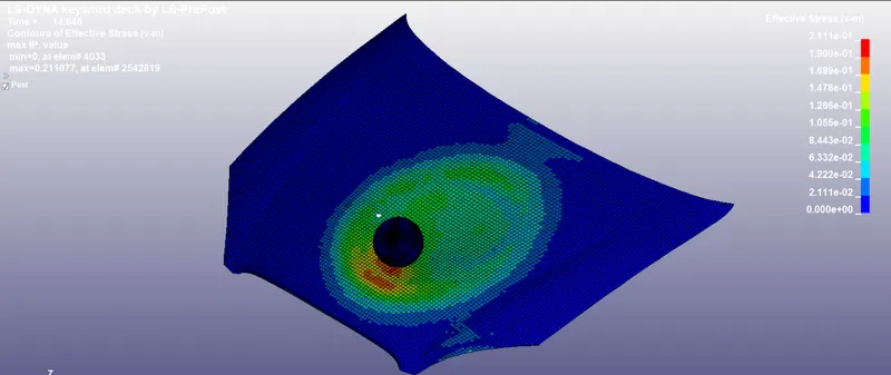
The Animation of Headfoam Impact Over the Aluminium Hood will be available at:
https://drive.google.com/drive/folders/1wFaixH768ddvCs-1yYnSnQmYrZI0tg5K
Case-3 Impact of Spherical Head Over Rigid Body
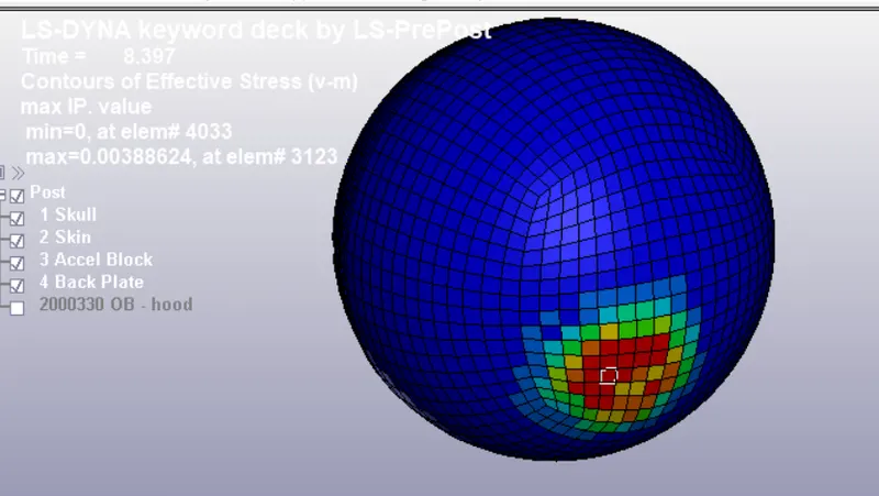
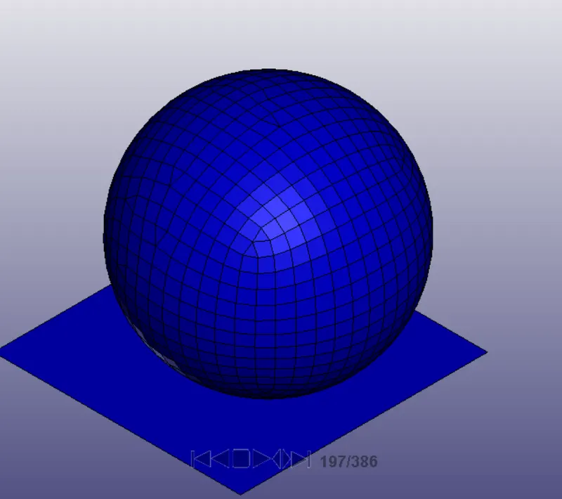
In this Case, the Head is modelled using Spherical Shell Elements. The Thickness of Shell Elements is given as 14mm to approximate Real world conditions. It is merely an Exercise for solving much complex problems. The Rigidwall is created for Impact simulation. The Entire setup is shown below.
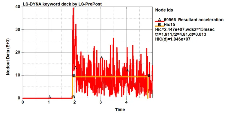
Automatic Single Surface Contact is created and the Acceleration of Node 69566 is recorded for HIC Calculations, The result is shown below. The HIC Value obtained is very High.
CONCLUSION:
1. The HIC Value can be reduced by reducing the impulse of force during Impact.
2. Material with more ductile properties will reduce the HIC Values.
3. Ductility Should be priotrized over the UTS of Material if the Objective is to reduce the HIC.
Since Output file is very large it cannot be attached with the answer. In attachments Only ASCII Files and K-files are included.
The result files are stored in the google drive:
https://drive.google.com/drive/folders/1Pt5u3E1fTBokjj1oK7f-P18sNaeF1gmZ