Week - 8 - Morphing
MODEL-1
Aim:
The Aim of this Challenge is to practise the Morphing Techniques using the CAD Model Provided.
Procedure:
The Morphing is a technique use to modify the shape of Design with out any numerical inputs. The Morphing technique can be applicable to both FE and CAD models. When we select the Morphing option from the Modules tab., we can see that the message of "Morphing active" appears in GUI., which will enable us to differentiate between normal Operations mode and Morphing Mode. The Below figure shows the activation of Morphing.
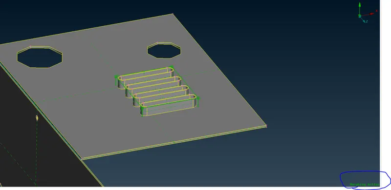
Once the Morphing is activated, the Features to be morphed is selected and the Morphing Box is created using "New" options under the modules Button. In the Figure above we can see the Morphing box is created around the Ribs feature. The Lcoal Coordinate System is created in the Middle of the Box and the Control Points of the Morphing Box can be moved to change the Design of the Feature. From the Below figure we can see that the Two Yellow points are designated as control Points and the Control Points are moved along the Y-Z plane, inorder to change the design of the feature.
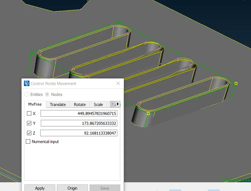
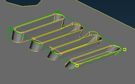
It is Important to Realize that Only the Control Points are moving in the Y-Z (refer below figure)Plane and the rest of the Points are fixed in space. Here only Y and Z axis are marked with tick and the Control Points can move only in Y-Z axis. The M-V Option Move the Control Points according to the Local Coordinate system.
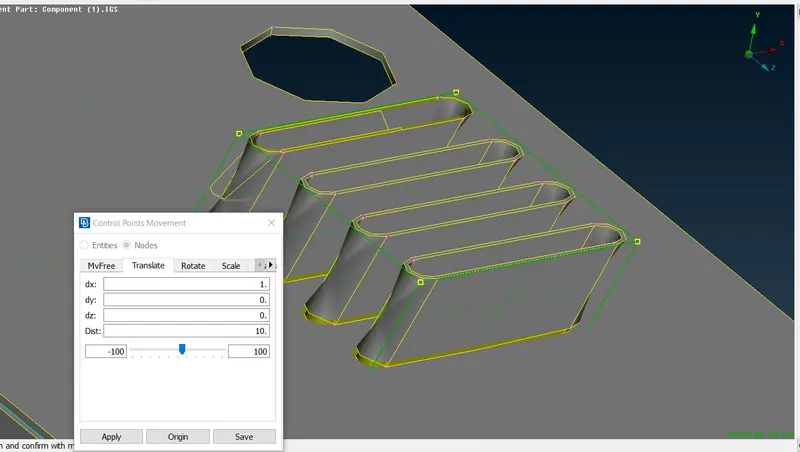
Next option is the Translate option which will move the Cotrol Grid with respect to Global Coordinate Refer the Below Image in which the Geometry is moved according to the Global Coordinate axis.
Next Option is the Rotate Option Which Can Perform Rotation of the Control Points about the Global Axis. Based on which the Geometry will be Altered. The Control Points selected are two blue points which perform rotation about Global Z-axis.
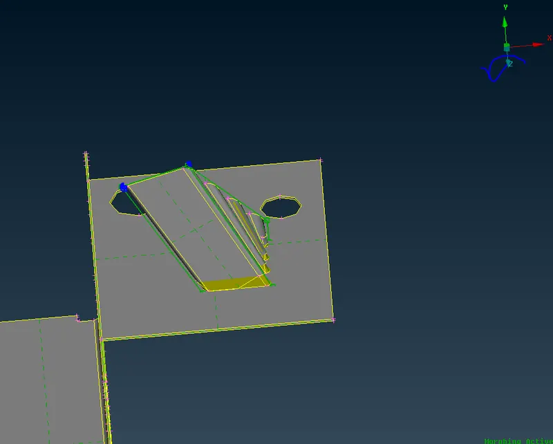
The Morphing boxes can be split into number of tiny boxes inorder to have more control over the shape of the Geometry and the technique is illustrated below, The Control Points are marked as blue and the Control points are moved along the Local Coordinate x-direction.
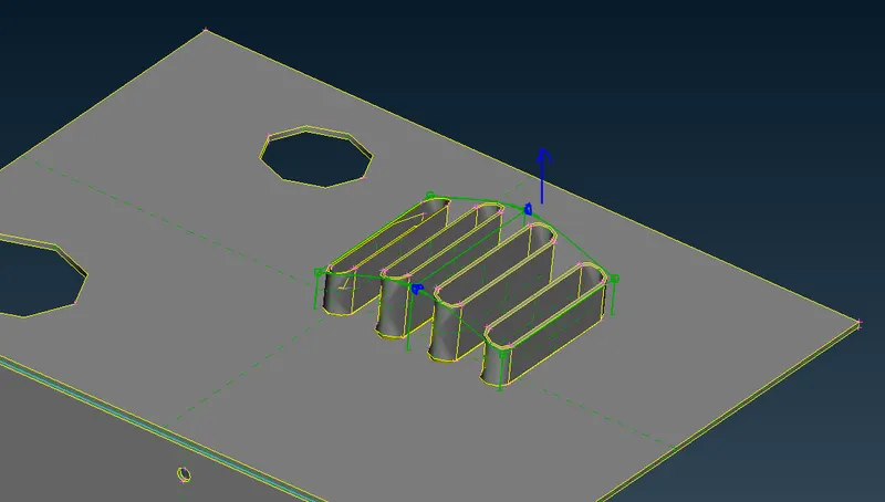
Similarly, all the Box Morphing Techniques are Practised using the Model-1. Final Morphed Geometry is shown below., where we can see that the shape is completly different from the Original CAD Geometry.
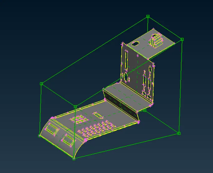
Model-2
Aim:
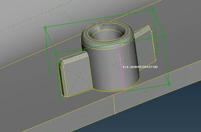
The Aim of this Challenge is to change the Heiht of Dog house and ribs provided in the CAD Geometry. The Height of the one Dog house before Morphing is shown below,
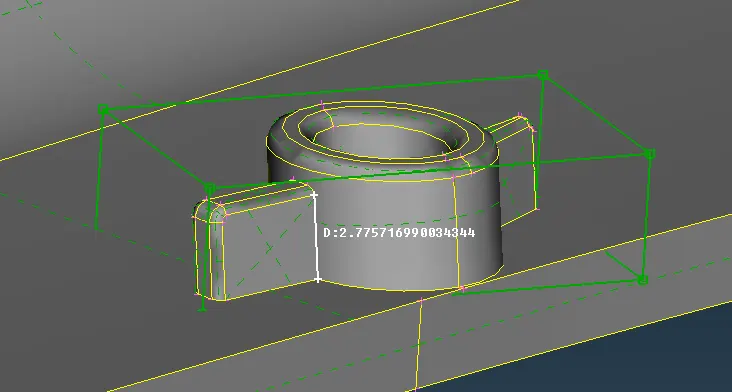
The Initial Height of Dog House is 2.77mm and it is changed to 6.46mm.
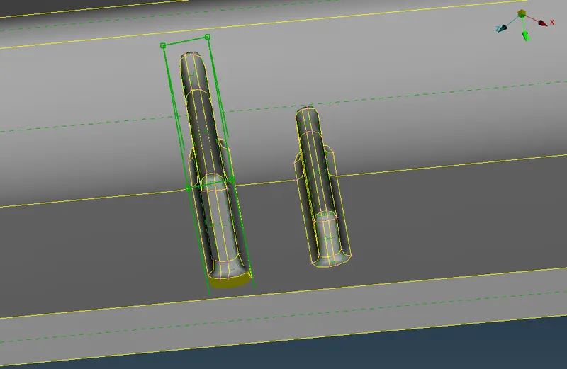
Below you can see the image of Rib one of which height is increased by Morphing and one height is un altered.
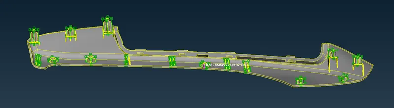
The Height of all the Ribs and Dog Houses are increased using Box option.
Conclusion:
The Morphing is done on Model-1 & Model-2.