Project - 2 - Meshing on the suspension Assembly
Aim:
The Aim of this Project is to Perform the Meshing of Automobile Suspension assembly. The Casted Components has to be solid meshed, and Components having Uniform thickness of less than 5mm has to be Surface Meshed.
Procedure:
The Following steps are followed inorder to complete this project,
1. Geometrical Checkup
2. Surface Meshing of Casted Components & Tyre using Tria Elements
3. Volume Meshing of Casted Components & Tyre
4. Shell Meshing of Uniform thickness Components
5. Providing Relevant Bolt & Weld Connections.
Geometrical Checkup
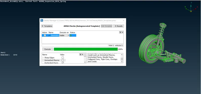
As a first step, the Entire Geometry is Checked for Geometrical Errors. These errors should be removed before Midsurfacing or Mesh Creation Process. In this Project, mostly all the Components are free from any geometrical errors. The screenshot for geometry Check up is given below.
Surface Meshing of Casted Components & Tyre using Tria Elements
The Surface Mesh is performed for the Casted Components, the Quality Critera is Provided for Tyre, Rim and Rest of oher Components, Firstly the Surface Mesh is Done for Casted Components complying with the Mesh Quality Criteria Requirements. The Surface Mesh Prepared for Some of the Components are shown below,
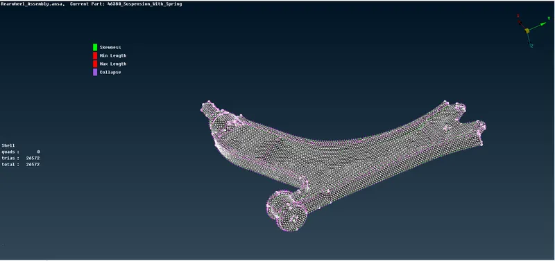

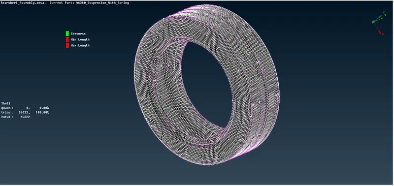
The Surface Mesh is generated for all the Casted Components & Tyre. The Surface Mesh Quality Critera is Different for Tyre & Rim,with the Target length of 6.5mm and for rest of other components the Target Length is 4. The Tria Elements is used in Flat regions and the Ortho Tria Elements are used to Capture the Curved Surfaces.
Volume Meshing of Tyre & Casted Components
Once the Surface Mesh is Completed for Tyre & Other Casted Components, the volume is Defined using the Define_Volume Option under the Volume Mesh tab. Once the Volume is defined the Solid Mesh is created using TETRA_RAPID or TETRA_FEM Options, Both Options are suitable for Creating the Mesh for Structural Analysis.
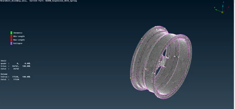
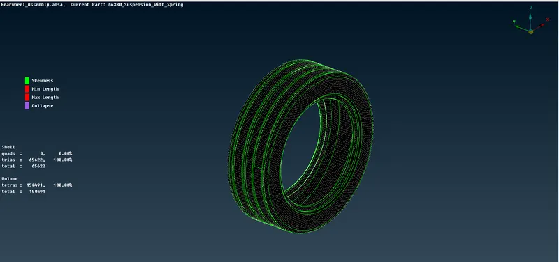
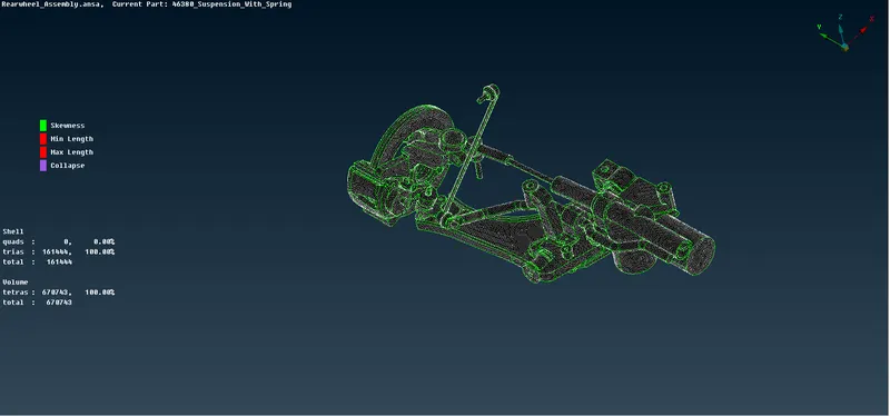
The Solid Mesh is Created and the Elements are Checked for Tetra Collapse Value of 0.2, The Failed Elements are Identified and Solved for Quality using the Fix Quality option in Volume Mesh.
Shell Meshing of Uniform thickness Components
There are some Components Present in the Model which having uniform thickness and also has the thickness less than 5mm, these Components are modelled as shell Elements complying to the Quality Criteria Provided.
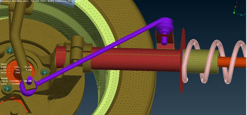
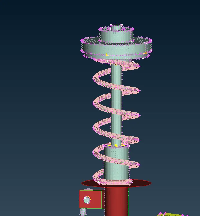
The Spring is Modelled as 1-D Beam Elements, using the Option of C-Bar under Nastran Tab.
Providing Relevant Bolt & Weld Connections
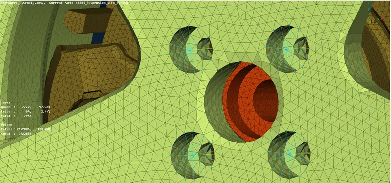
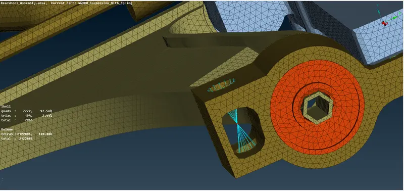
The Relevant Bolt Connections are Given for the FE Model inorder to Rigidize the Geometry to perform NVH Analysis in Nastran Software. The Bolted Connections in the FE Model are rigidized and some of the screenshots are provided below,
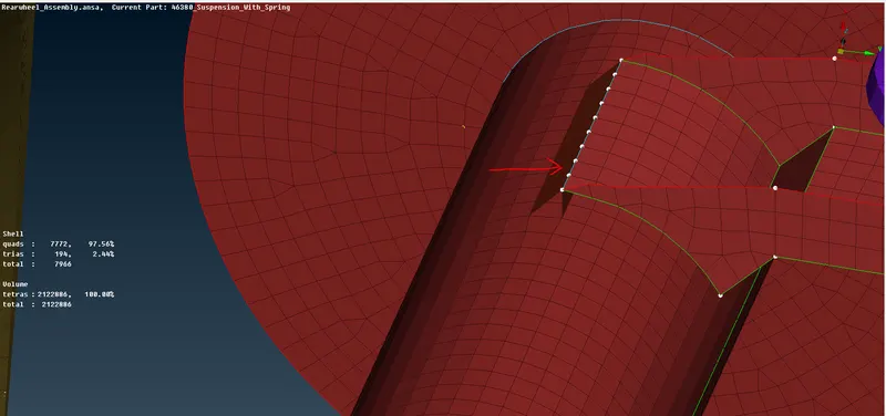
The Weld Connections between the two Shell Elements are realized as Lap Weld Joint.
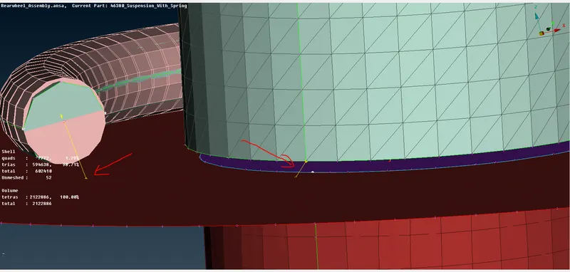
The Solid Mesh & Surface Mesh is Joined using the RBE-2 Elements as shown below,
LEARNING OUTCOMES:
1. Solid Meshing of Casted Components is learned & Practised
2. Shell Meshing of Uniform thickness Components is learned & Practised
3. Spring Element Modelling is Learned & Practised
4. Connections is learned & Practised.
Note: I have attached file compressed with .7z Extension because Zip file is more in size and cannot able to attach.
CONCLUSION:
Meshing of Automobile Assembly is Done.