Week- 5 - Solid meshing
AIM
The Aim of this Challenge is to create the Solid Mesh for the Mirror Part, satisfying both the Quality requirements for surface mesh and Volume mesh.
PROCEDURE
The Following Steps are followed while completing this challenge:
1. Geometry Clean up
2. Defeaturing
3. Surface Mesh Creation
4. Volume Creation
5. Volume Mesh Creation.
1. GEOMETRY CLEAN UP:
Before Starting to create Mesh, it is necessary to remove the Geometry Errors and hence the Geometry Cleanup is very essential to create a better mesh and mesh flow. The Given geoemtry is the "Rear View Mirror" and it has the Geometrical Errors. There are totally 11 Errors mostly comprised of Triple Cons and Needle Faces.
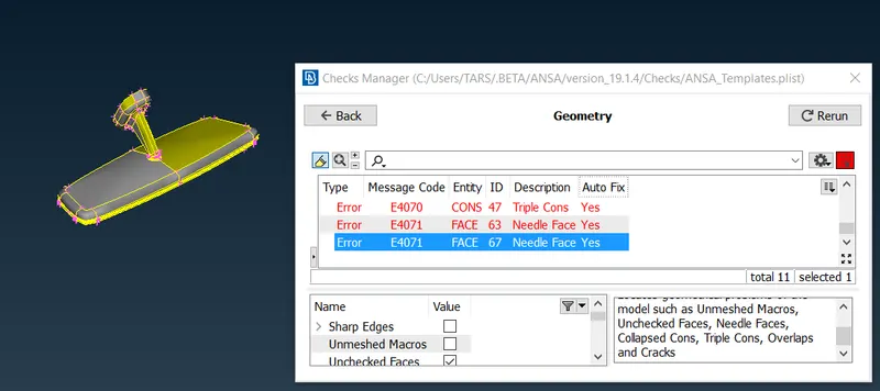 Figure:1 Before TOPO Cleanup.
Triple Cons are generated in this model because of the Closer Surfaces. Hence each Componennt is opened seperately and the Triple cons are removed by releasing it and again performing the TOPO. The Needle faces are removed by deleting the needle face and pasting the single cons togeather. All the Geometrical Errors are removed before proceeding for Defeaturing.
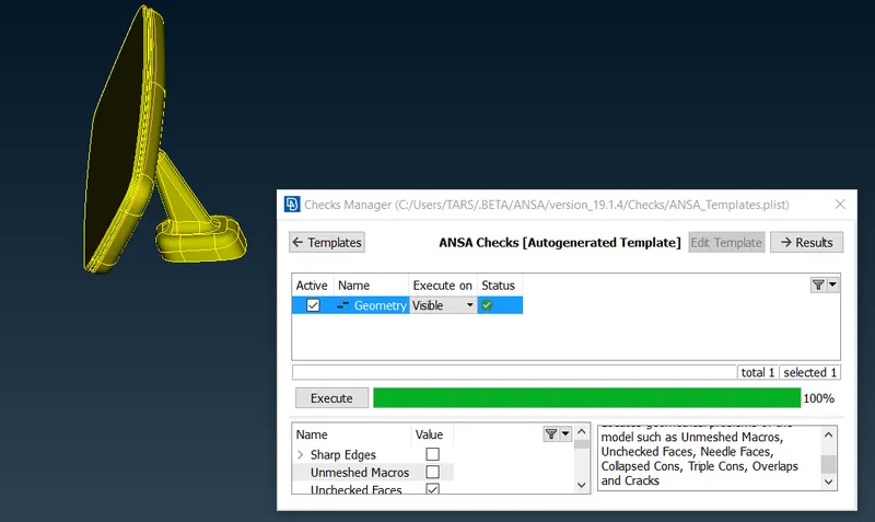 Figure:2 After Topology Cleanup.
2. DEFEATURING:
The Minimum & Maximum Length Criteria Given for the surface mesh is 0.5 & 2mm. Hence Defeaturing is essential in the areas where the Minimum Length Criteria will not be acheived. some of the Areas where the Defeaturing is performed is shown below.
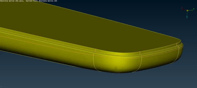 Figure 3 Defeaturing of Geometry
3. SURFACE MESH CREATION:
The Surface has to be Meshed with Tria Elements (Ortho Tria & Normal Trias) and the minimum and Maximum Length Criteria should be satisfied. Hence the Surface is meshed with Tria Elements for each components seperately. The Results are Provided below.
1. Spherical Joint
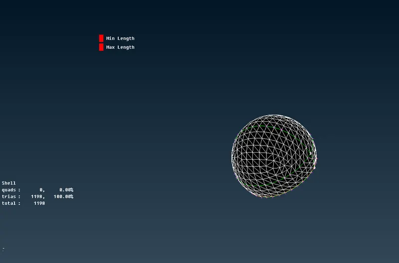 Figure 4 Spherical Joint Shell Meshing
Comments: No OFF-Elements & NO Quad Elements.
2. Mirror Bracket
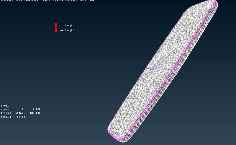 Figure 5 Mirror Bracket
Comments: No OFF-Elements & NO Quad Elements.
3. Mirror Stand
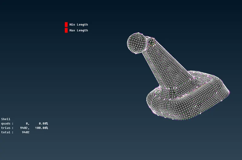 Figure 5 Mirror stand.
Comments: No OFF-Elements & NO Quad Elements.
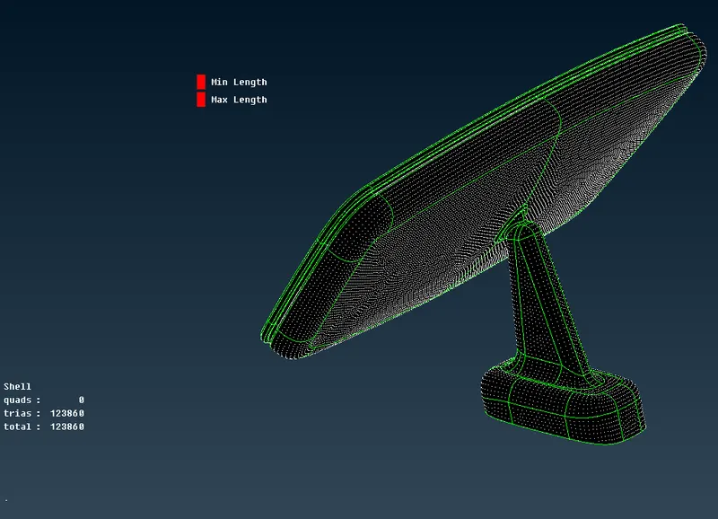 Figure 6 Total Shell Mesh.
Comments: No OFF-Elements & NO Quad Elements.
4. VOLUME CREATION.
After the Surface Mesh is Created, the Volume is Defined using the "Define" command in the Volume Mesh Tag. When Creating the Volume, I Experienced the Intersections Error between the Spherical Joint and the the Mirror Bracket part and I Solved this Error by defining the Volume Seperately for the Two Components.
Figure 7 Intersection Error
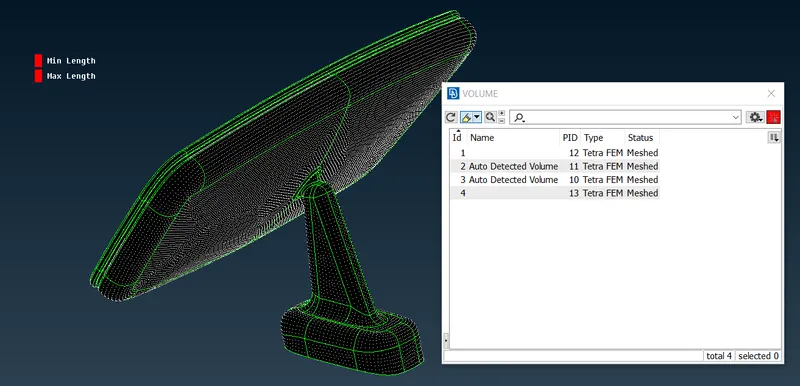 Figure 8 Volume List.
5. VOLUME MESH CREATION.
Once the Volume is defined, the Volume Mesh is created using the Tetra FEM Option, after some brief period of time the Solid Mesh is Created for Each and Every Part. The Volume Mesh is Checked for the TET_COLLAPSE of 0.2 and there are no OFF-elements.
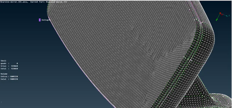 Figure 9 TET_COLLAPSE.
Learning Outcomes:
There are many learning outcomes regarding solid meshing, some of them are listed below,
1. Generation of Volume using Define option in VOlume Mesh Tab.
2. Generate Volume Mesh using TETRA Elements.
3. Checking for TET_COLLAPSE
4. Improving the Quality for elements which fails to meet TET_COLLAPSE criteria using MV_free option and fix Quality Option.
Conclusion:
The Solid Mesh is Created for Rear Mirror.