Week - 5 - Modelling Spotwelds
Aim:
The Aim of this Challenge is to Create a Crash simulation of Brackets by Modelling Spotwelds.
Procedure:
There are many ways to create the spotwelds, Here the following two methods are demonstrated for spotweld Creation.
1. By Modelling spot welds as Beams
2. By Modelling spot welds as solid Elements.
Case-1 Modelling spot welds as Beams
The Beam Elements are created using "Element Generation option" under "Element & Mesh" Tab. The Beam Elements created is shown below.
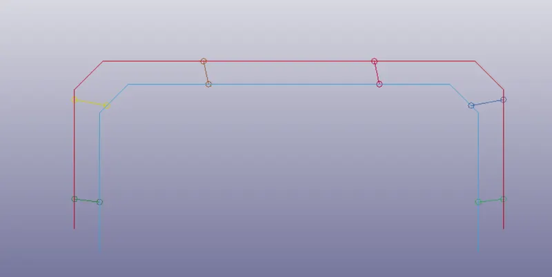
Figure-1: Beam Elements Created for Spotwelds
The Material to be used for Spotweld is MAT-100, the Material ID is created and the steel properties are assigned. The maximum axial, shear & Resultant Force for Spot weld Failure is specified as 4000N. Similarly the Maximum Resultant Moment for spot weld failure is specified as 4000N-mm.
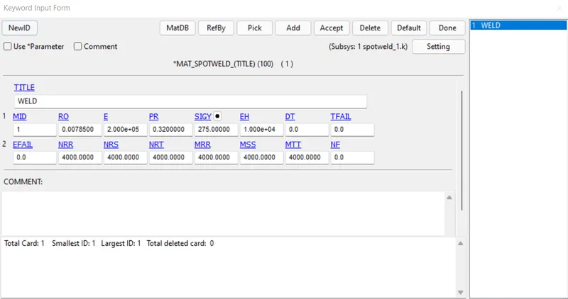
Figure-2: Material Card for Spotweld
Under the Section the Section is defined for beam using Keyword "*SECTION_BEAM" option. The Element formulation chosen is 16 (Fully integrated Beam Element) with Gaussian Quadracture specified as 4X4. The CST (Cross Section) is specified as 1, corrosponding to Circular Cross Section. For Circular sections we can specify outside & inside diameter at node-1 & node-2. for a solid Circular section the inside diameter can be specified as zero. (The TT1 & TT2 specified as Zero)
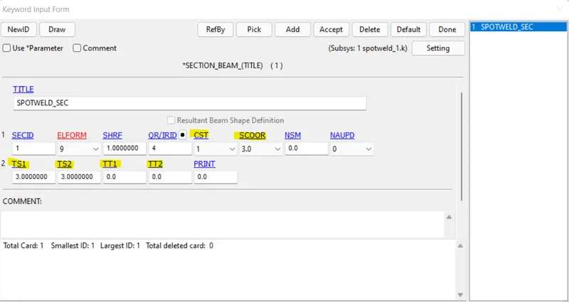
Figure-3 Section Defnition for spotweld.
SCOOR value is set to 3.The Shear force developed by the beam will produce a torque equals to (shearfoce * beamlength/2), which is not accounted for by the beam rotational stiffness alone. This torque contribution is necessary to give realistic beam-like behaviour. Hence SCOOR value is set to 3. If SCOOR Value is set to 3, the angular velocity at N2 rotates the triad, and the rigid body rotation is measured and the rotation strain is modified so that rigid rotation doesn't create any strain.
Once the Material & Section is defined for the Beam Elements, then Corrosponding Spot Weld Part ID can be created.
BOUNDARY CONDITIONS:
The SPC boundary conditios is defined as shown below by using NSID-1. The All Degree of freedom is restrained except for the x-direction translation.
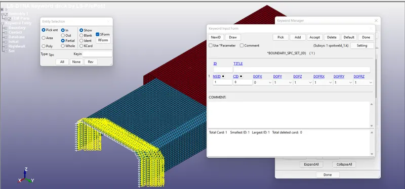
Figure-4 Boundary Conditions
CONTACT:
The Contact between Spotweld Beams and the shell Elements is established by "TIED_SHELL_EDGE_TO_SURFACE" option.There is a possibility that the Spot weld may fail during the Simulation and the two brackets will come into contact with each other. Hence Automatic Single surface contact is created.
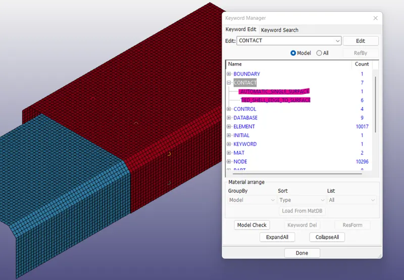
Figure-5 Contact
CONTROL CARDS:
SSTHK option in Control Contact is set to 1 to include actual Shell thickness in the Contact Calculation process. Since the Weld is created between the two nodes of bracket and the actual shell thickness is considered, the initial penetration is reported in the output file. Since We modelled 6 spotwelds 6 Penetration warnings appear in the lsrun.out file.
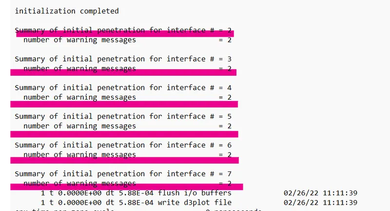
Figure-6 Initial Penetrations
HGEN value in the CONTROL_ENERGY card is set to 2, which include the Hourglass Energy in the Energy balance.
RIGIDBODY:
Planar Rigid body is created with Plane normal facing the FE_model.
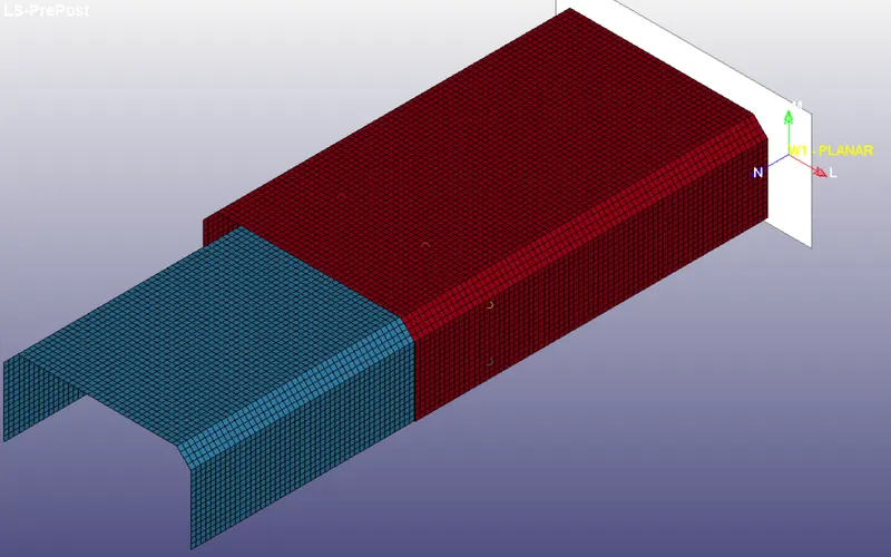
Figure-7 Planar rigid Body.
Case-2 Modelling spot welds as Hexa Element
In case-2, the spotwelds are modelled as Hexa Elements. The Hexa elements are modelled using Element editing option under Elements & Mesh tab. The Beam Elements in the previous case are replaced by the Solid Hexa element and the SECTION_SOLID is created with Element formulation-1. The Contact between the Solid spotweld & Shell elements is established by "CONTACT_SPOTWELD" option. This is the only change in case-2 with respect to case-1 rest of the Setup remains same.
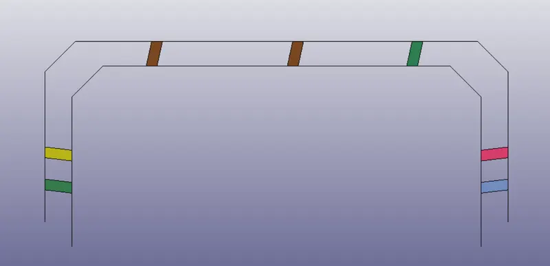
Figure-8 Solid Spot weld modelling.
OUTPUT DEFNITION:
The ASCII outputs and the Binary outputs are defined as below, The termination time is set at 5ms and the timestep is kept at 0.006ms to avoid contact instabilities.
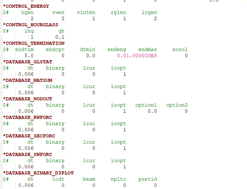
Figure-9 Output Defnition
CASE-1 & CASE-2 RESULTS
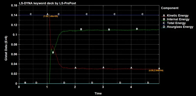
Figure-10 Energy Plot of Case-1
The Decrease in Kinetic Energy of the System is 110.6 joules. From the Plot we can understand that Total energy remains constant, there is decrease in Kinetic Energy & increase in Internal Energy of the system.
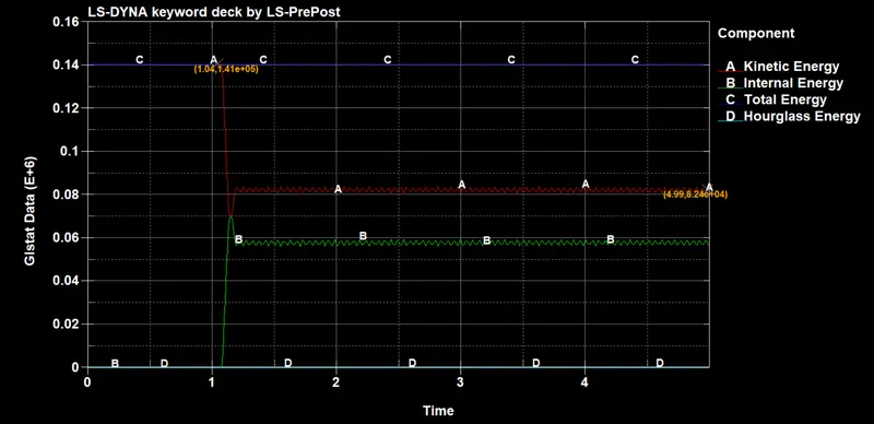
Figure-11 Energy Plot of Case-2.
The Decrease in Kinetic Energy in Case-2 is estimated to be 58.6joules.
VONMISSES STRESS @ TIME OF IMPACT:
The Vonmisses stress at the time of impact in Case-1 is 395Mpa, The Yield stress is specified as 355Mpa, hence there is plastic deformation.
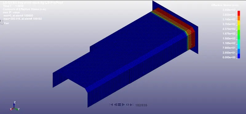
Figure-12 Vonmisses Stress at time of impact - Case-1
The Vonmisses stress at the time of impact in Case-2 is 393.7Mpa, The Yield stress is specified as 355Mpa, hence there is plastic deformation.
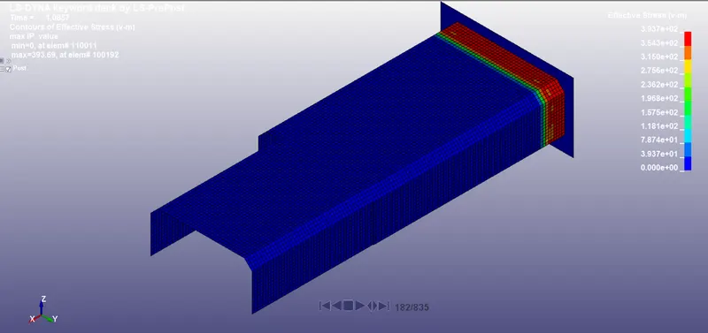
Figure-13 Vonmisses Stress at time of impact - Case-2
MAX_EFFECTIVE PLASTIC STRAIN:
Maximum Effective Plastic strain in Case-1 is observed to be 7.59%
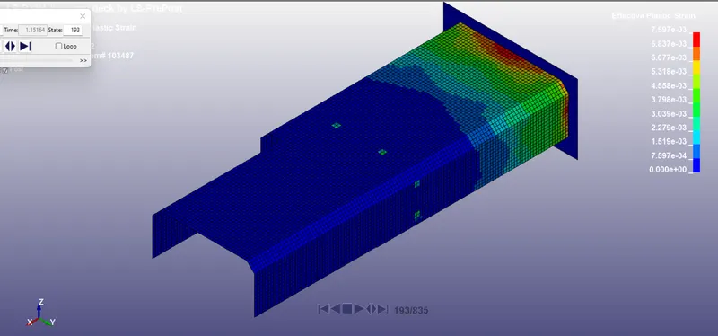
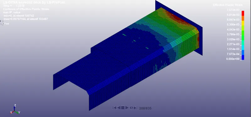
Maximum Effective Plastic strain in Case-2 observed to be 7.57%
TIME OF WELD FAILURE:
Case-1
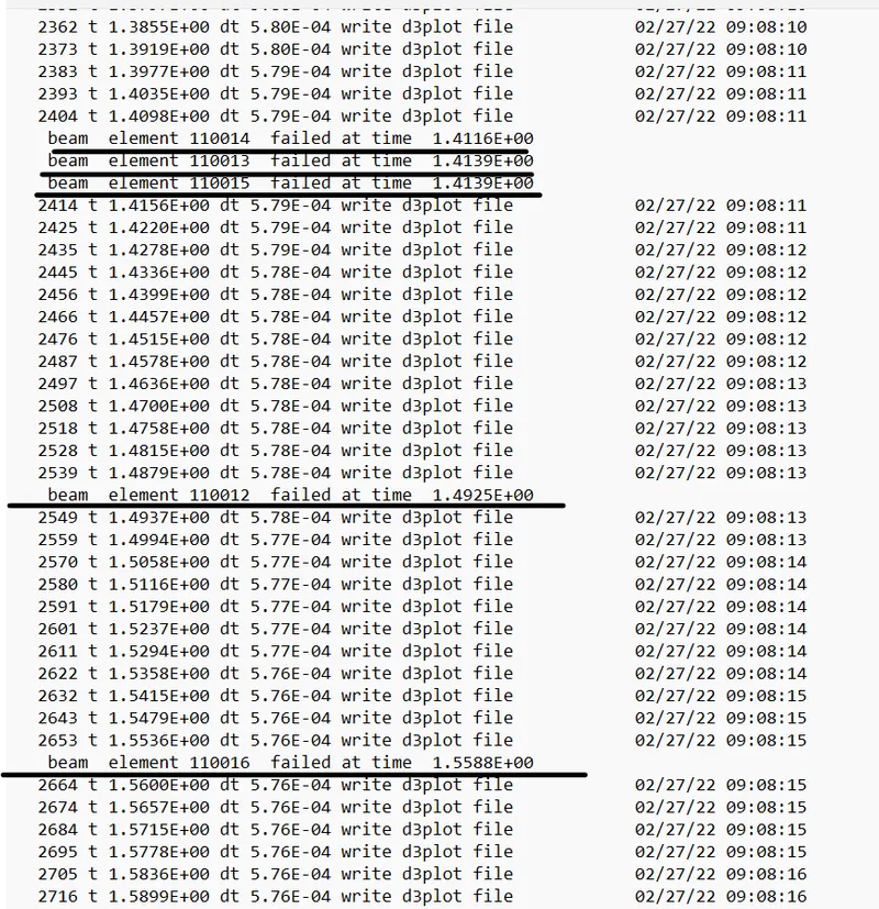
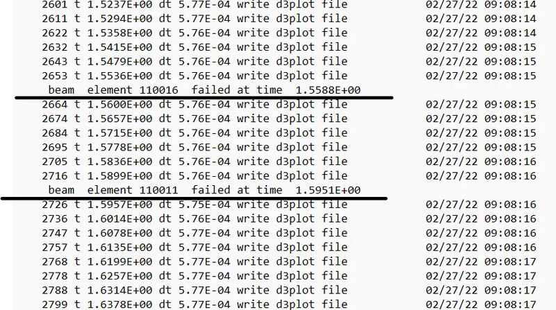
Totally 6 welds failed of which 3 Welds Failed at the time of 1.4116ms & we have 4th Weld failure at 1.492ms , the 5th weld failure at 1.558ms and 6th at 1.595ms.
Case-2:
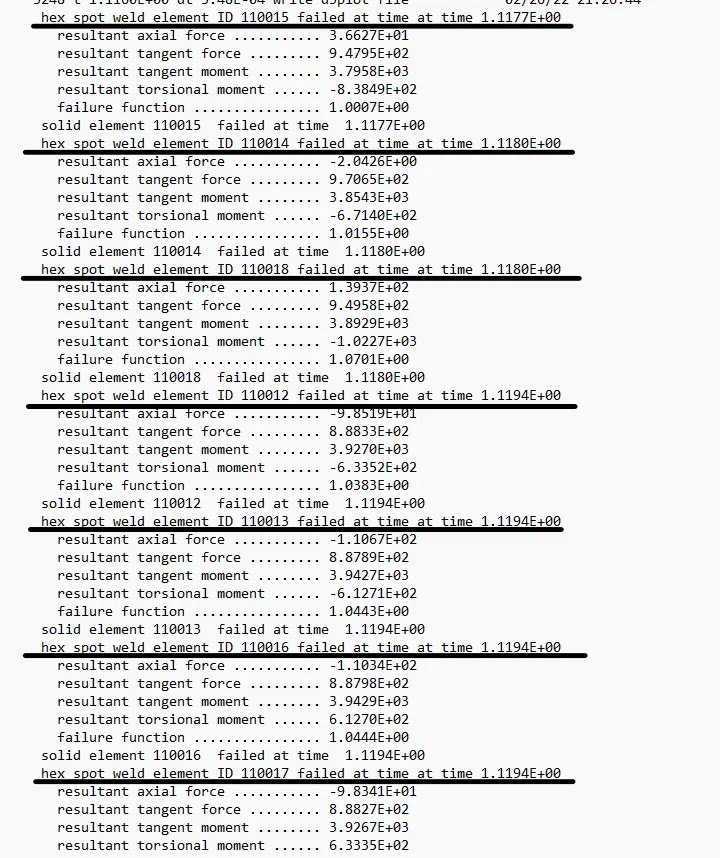
Case-2 Reported 7 Weld Failures at the time of 1.11ms.
SPOTWELD RESULTS:
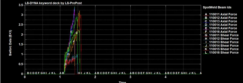
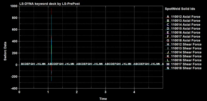
The Axial & Shear force experienced by the Spotwelds for two cases is shown below. In Case-1 we had weld failures at various time range from 1.41 to 1.595 ms hence the graph is very noisy. In case-2 all the spotwelds fails at 1.11ms, hence the graph is not very noisy.
Case-1
Case-2
Acceleration experienced by Node:
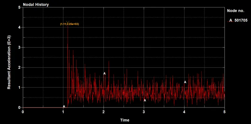
Case-1
The Nodal Accelerations experienced by the Node- 501705 (This node is in upper Bracket) is shown below, the maximum acceleration experienced is 4.55e3 mm/ms2 at the time of contact.
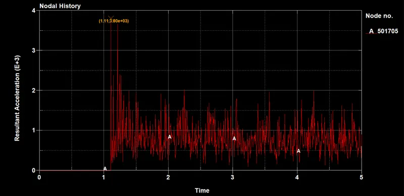
Case-2
The Maximum acceleration experienced by the nodal point 501705 is 3.80e3 (This node is in Upper Bracket) at time of contact.
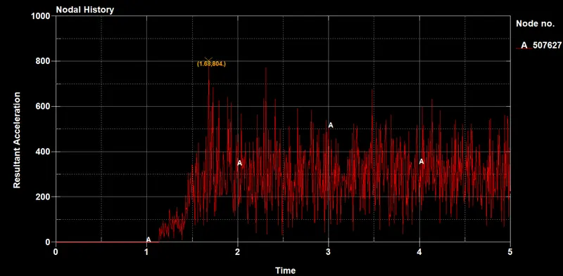
The node-507627 (Case-1) is in lower Bracket which experience much lesser accelerations compared to 5017055.
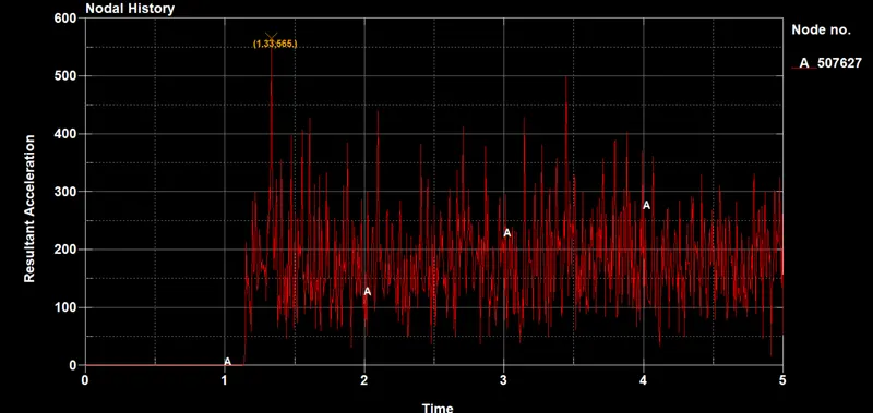
The node-507627 (Case-2) is in lower Bracket which experience much lesser accelerations compared to 5017055.
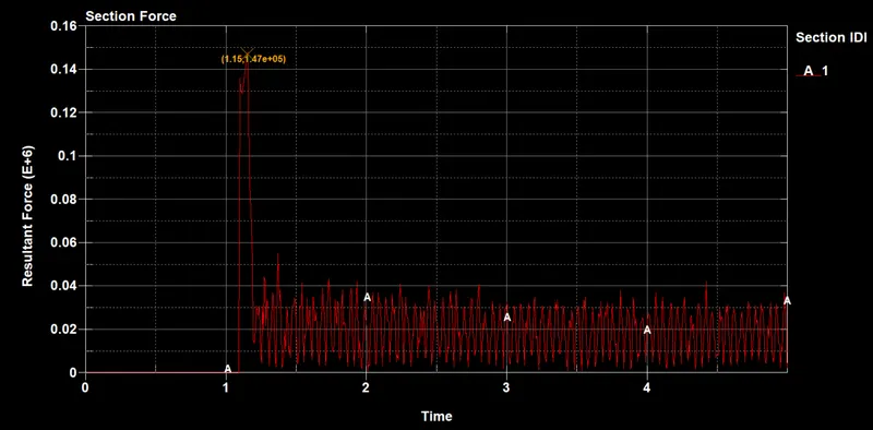
SECTION FORCE:
Case-1:
case-2:
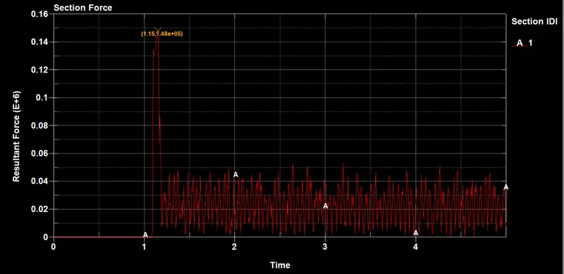
The Maximum Force experienced at the cross_section is 1.48e5N.
Conclusion:
Spotweld simulation is performed by modelling the Spotweld as Beam element and Hexaelement. The result obtained are similar in both cases.
Note: The results Presented in the report are obtained using the timestep of 0.006ms (less than critical timestep). Since the output file is greater than 200mb, it cannot be uploaded. Hence only the results & Final K-files are uploaded.