Week - 4 - 2D meshing for Plastic components
AIM:
Aim of this Challenge is to extract the Mid surface of the Plastic component and model the Mid surface using 2-D Shell Elements. The Mesh Quality Criteria is Provided for shell modelling and it is also mentioned to keep the Off elements which are impossible to remove.
PROCEDURE
The Following Steps are Carried out inorder to complete the FE-Modelling.
1. Thickness Measurement
2. Topology Cleanup of the Geometry
3. Mid Surface extraction of the Geometry
4. Meshing of the Geometry.
1. THICKNESS MEASUREMENT:
The CAD Geometry is imported in to the ANSA and the Thickness was measured at various places, The CAD Geometry Contains features with Different Thickness (Different Features with Different Thickness), and also the features with Varying thickness(Same Feature with Varying Thickness). One of the Example of feature with varying thikness is shown below. From this we can understand this CAD Geometry has features which have varying Thickness. The Ribs Present in the CAD Geometry has varying thickness.
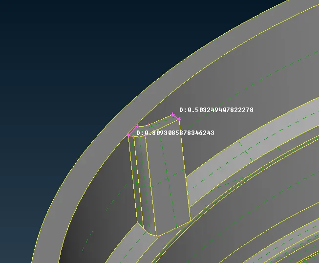
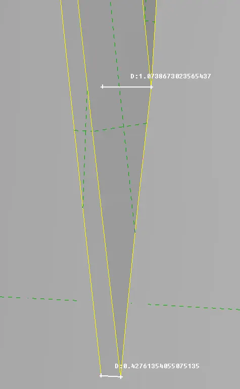 Figure-1 Thickness Measurement
2. TOPOLOGY CLEAN UP
After taking Thickness Measurements at different Positions in the geometry, now I get the Idea on how the thickness of the Parts are Varied. The Next step is the Topology Clean up. The Geometry is checked for unchecked Faces, Needle Faces, Triple Cons, Overlap Faces, Cracks and Single Cons. The Geometry Error was Identified and Cleaned. Screenshot is attached before and after topology Cleanup.
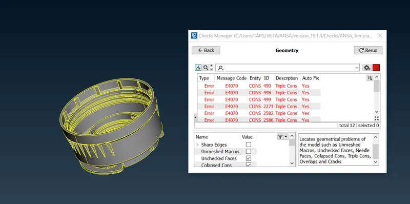 Figure:2 Before Geometry Cleanup.
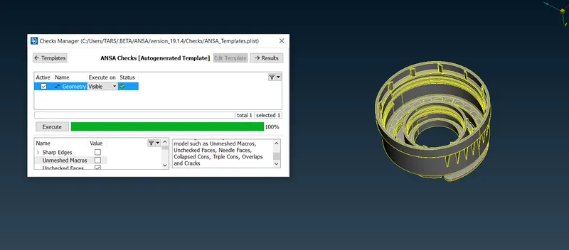 Figure:3 After Geometry Cleanup
There are 12 errors in the Geometry and they are eliminated by Geometry Cleanup.
3. MID SURFACE EXTRACTION OF GEOMETRY:
The Highlighted faces are offseted using the Offset comments inorder to create the Mid surface. Once the Offset option is envoked we can provide the offset distance and the Midsurface offset surfaces is created. This option is used for feature which have uniform thickness and hence it is used on the Features highlighted in the below figure.
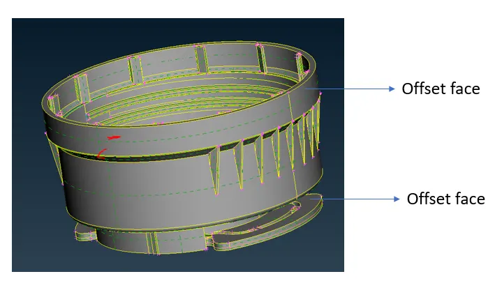
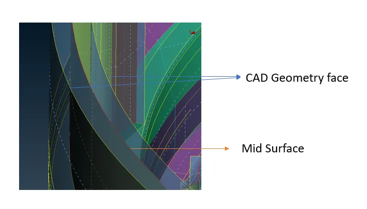
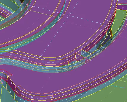
Fig:4 Mid surface Extraction using face offset.
After Offset Option performed, the Midsurface is Checked whether it falls perfectly between the Geometric faces.
There are many techniques to Extract the Midsurface of the Plastic Components such as Faces-Middle option and Curves- Middle Option etc., almost all Options are used to Extract the Midsurface of the Entire Geometry. The Extracted Midsurfaces are assigned Correct Thickness. The Ribs Present in the CAD Geometry has various Thickness and hence they are Cut into many parts using FACES-CUT option and the Different Thickness are assigned. The Various Thickness are assigned using the Properties Tab.
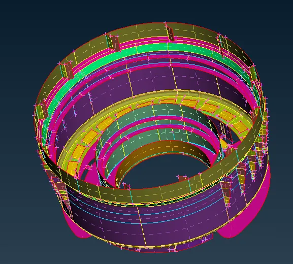
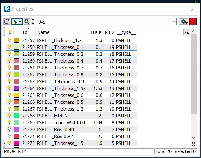
Figure:5 Assigning Thickness for Mid Surface.
You can see from attached Screenshot Various thickness Properties are Created for Each Features. Midsurface Extracted is Checked by assigning different Property for midsurface and the parent CAD Geometry. The Midsurface is Perfectly formed between the parent CAD Geometry Faces. Hence the Mid Surface Extraction is Successful.
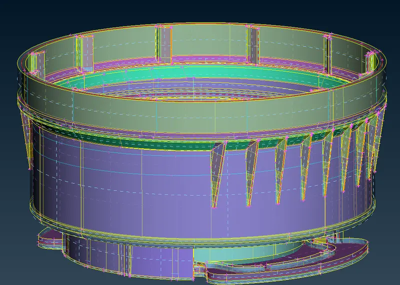
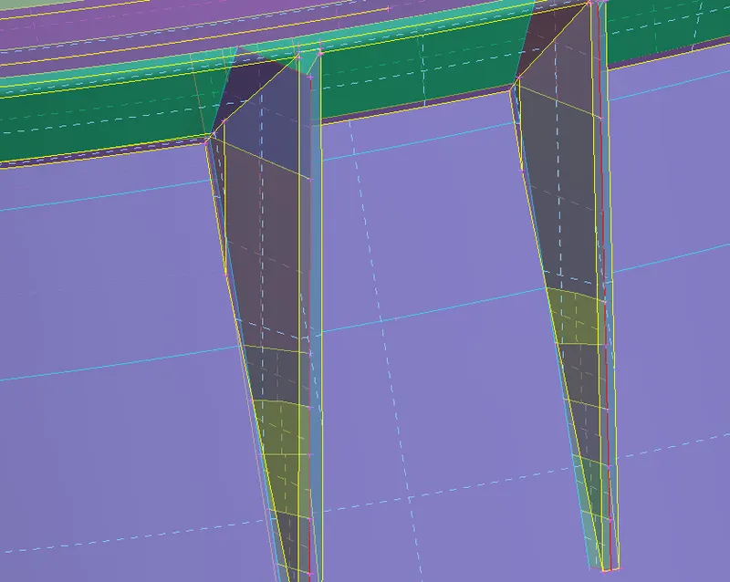
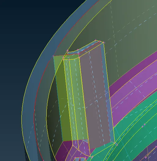
Fig:5 Checking of Mid Surface Extraction.
MESHING OF THE GEOMETRY:
The Meshing operation is Performed for the Extracted Midsurface, The Quality Criteria is Provided as input and the Target Length is Set as 1mm. The Maximum length is 3mm and Minimum Length is 0.5mm
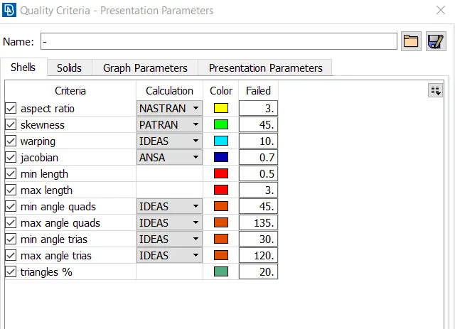
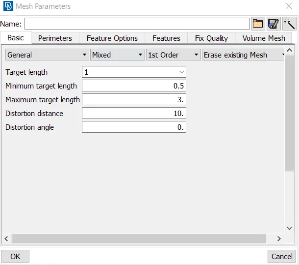
Fig:6 Mesh Parameters.
There are Some Failed Elements in the FE-Model, because the Midsurface has the Triple cons which cannot be Supressed and the Orientation will affect the Mesh Flow. Apart from the Regions where the Failing of Elements cannot be avoided, all other regions are meshed with Good Mesh flow.
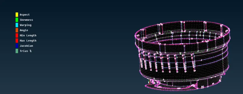
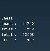
Fig:6 FE-Model with Number of Elements.
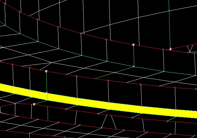
The Main Reason for the Off-Elements is the small region between two triple Cons where We cannot able to do anything to correct the Quality. The Screenshot is Provided below, where we can see that the all the Elements between the Two Triple Cons are Failed for aspect ratio and minimum Length Criteria.
CHECKING ELEMENT THICKNESS OF SHELL MESH
After Meshing Performed the Element Thickness of the Shell mesh is checked, for ribs with Varying thickness the Midsurface is divided into many parts using FACE-CUT option and the different thickness is assigned. The Screenshot is attached before and after enabling the Element thickness.
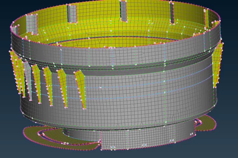
Fig:7 FE-Model without Element Thickness Enabled.
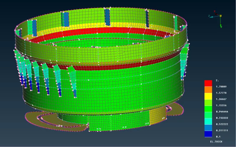
Fig:8 FE-Model with Element Thickness Enabled.
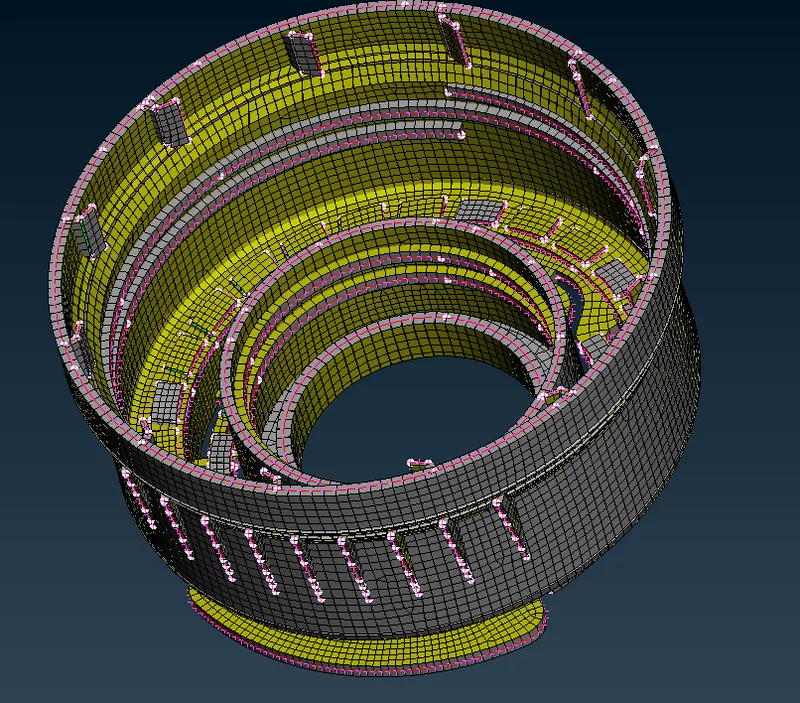
Fig-9 FE model with" Draw Shell as Solids"
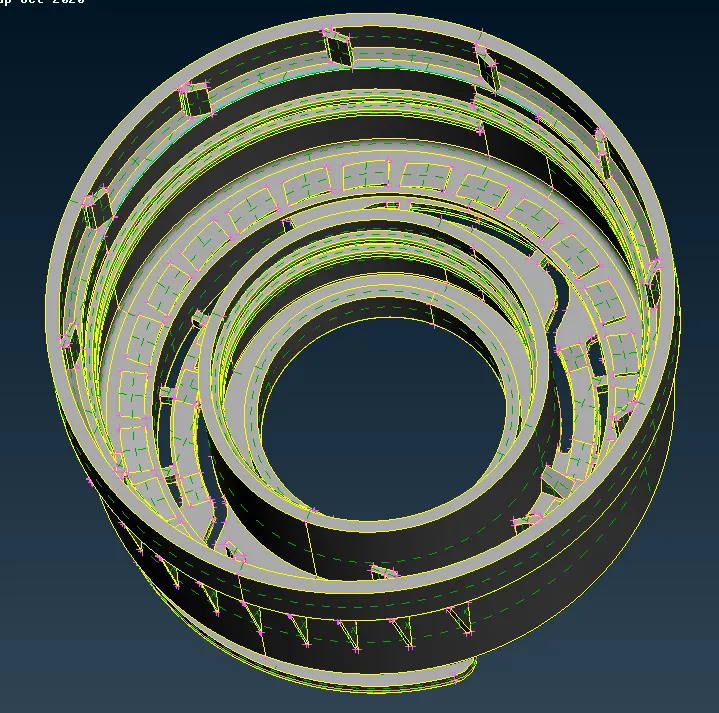
Fig-10 Original Cad Model
Original CAD Geometry is compared with FE-Model and the Model is found to be Good Approximation of CAD Geometry.
LEARNING OUT COMES:
- Various Techniques for Extracting the Midsurfaces are learned.
- Extracting the Midsurface for Somewhat Complex geometry of Plastic Components is learned and Practised Well.
- The Practise Geometry Provides Very Good Learning Practise and it Provides necessary experience to Complete the Challenge on time.
- I am very Confident about Extracting of Midsurface after Completing this Challenge.
CONCLUSION:
The Mid-Surface of the Plastic Geometry is extracted and the FE-Model is Created.