Week 8-3D Tetra Meshing Challenge
Aim:
The Aim of this challenge is to create a Tetra mesh for the Given geometry.
1.Housing Model
For First model, the Surface Tria elements has to be created with target element size of 5mm, Max element size = 7mm and min element size = 2mm, then the 3D Tetra mesh needs to be created which will meet the minimum TET collapse value of 0.15
2D MESH
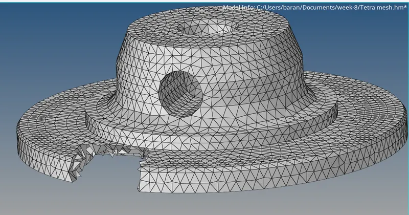
The 2D Surface mesh is created as shown below considering the Maximum and minimum Element quality criteria. For the Fillet regions R-trias are created and for the non fillet regions the Normal trias are created.
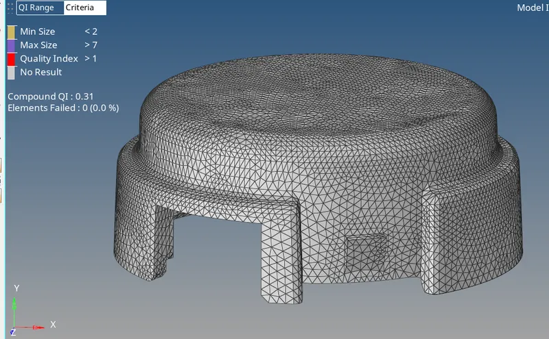
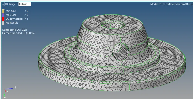
Once the surface trias are created, the Tetra mesh is created using Tetramesh option under 3D Tab. The Tetra mesh for the housing compenent is shown below.
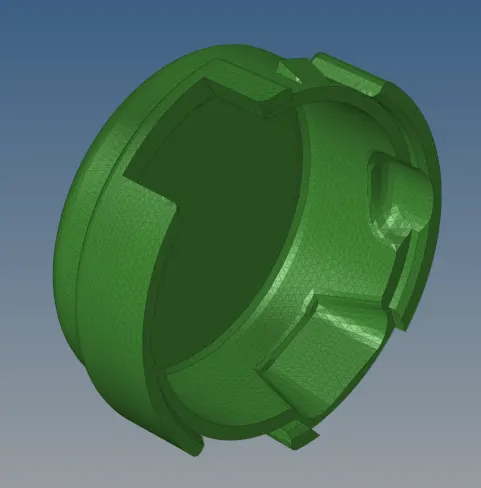
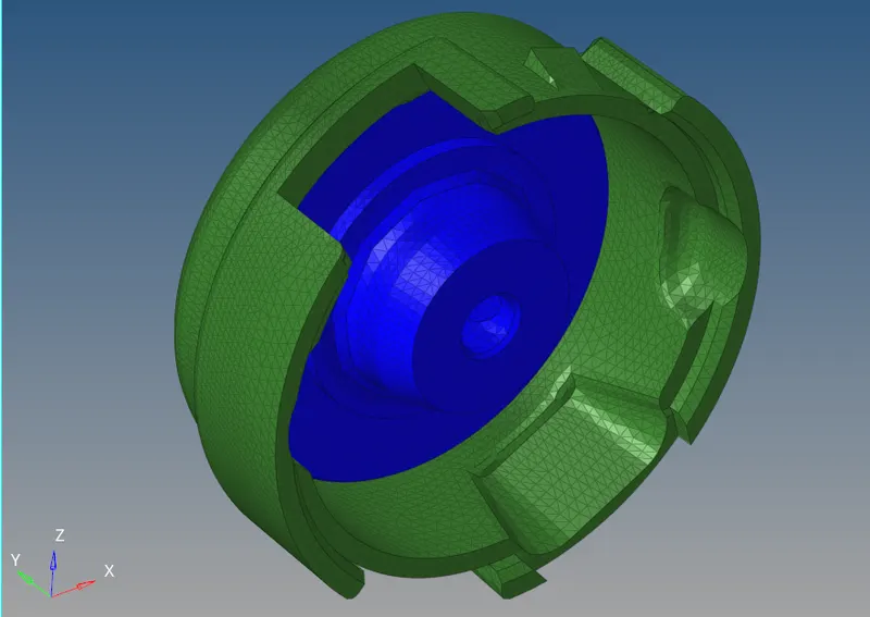
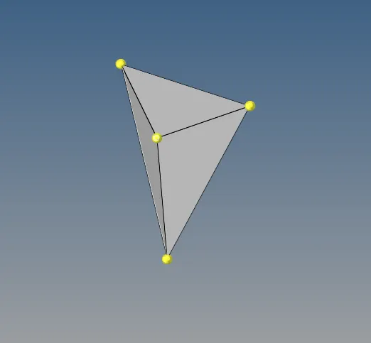
Once the 3D Tetrahedron elements are created, they are checked for the TET Collapse value of 0.15. There are some elements in the FE model which are failed for the TET collapse value of 0.15. Such Elements are manually Cleared. Once the Tetra meshing is completed, Tet Collapse quality criteria is checked using Check elements option under tools tab. The failed elements are saved and retrieved using the Mask Elements option. Once the Failed components are retrieved, the Temporary nodes are added by pressing Shift+F2 (Temp Nodes). The Temporary nodes are added for the failed elements to identify surface and non surface nodes. One such Failed Tetra elements with added Temporary nodes are shown in figure.
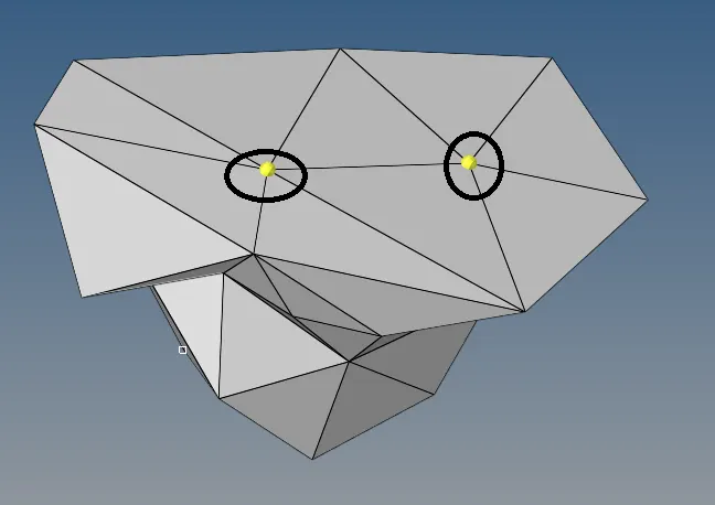
Once the non surface node(as highlighted in above image) is found out the Height of the Tetra element is increased by translating(Shift+F4) the non surface node. In this way the TET collapse value of the failed element is improved. Once clearing all the element for TET collapse, the model is saved.
TET Collapse Mapping & Distribution of the Housing Model are shown below,
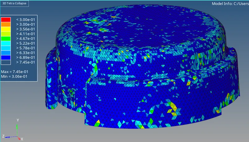
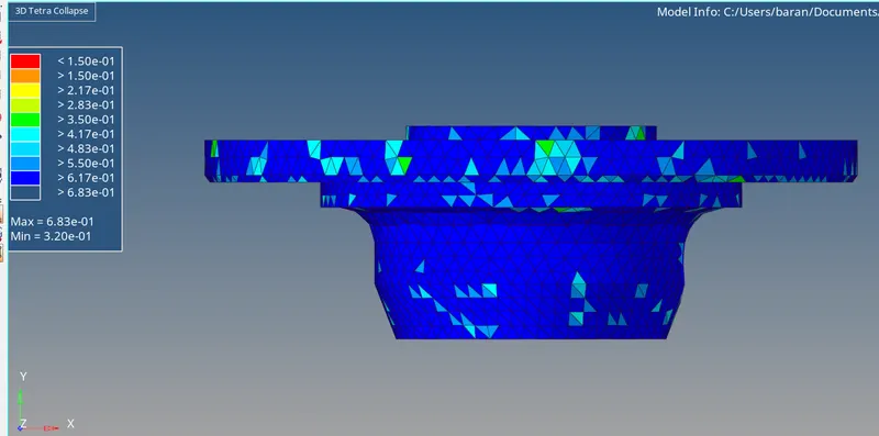
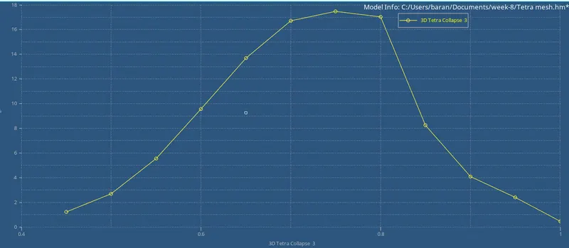
From the TET Collapse distrubution plot, we can see that about 80 percent of elements in the FE model are within TET collapse range of 0.6 to 0.9.
Model-2
The Second model is imported into the Hypermesh. For Model-2 the Tetra mesh is generated using Volume Mesh option under 3D Tab. The Target element length is specified as 3mm.

Once the Tetra elements are created, they are checked for the TET collapse quality criteria, the Failed elements are seperated and cleared for this Mesh quality. Once all the Failed elements are cleared for quality, the Elements are checked finally using Check elements option under tools tab to verify all the tetra elements are cleared for Quality criteria.

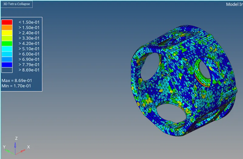
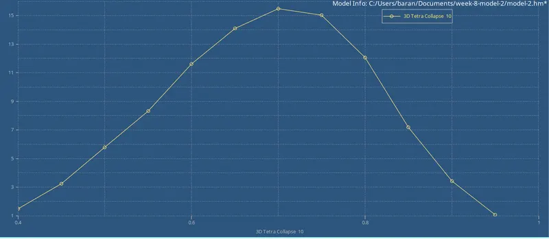
TET Collapse Maping & Distribution are shown below, From the Below plot, we can understand the Minimum Tet Collapse value in the FE model as 0.170 > 0.150. From TET collapse distribution graph, 63 percent of the elements fall in the TET collapse range of 0.6-0.9.
Model 3
The Model-3 is imported into the hypermesh, The model consist of four components 1. Casing 2. Hub 3. Supporting Plate 4. Holder housing.
The Tetra mesh for Casing , Hub and holder housing is created using Volume mesh option and For Supporting Plate using Quick mesh option. Once the mesh has been created, the Elements failing for Tetra mesh is cleared manually just as we done for model-1 & model-2.
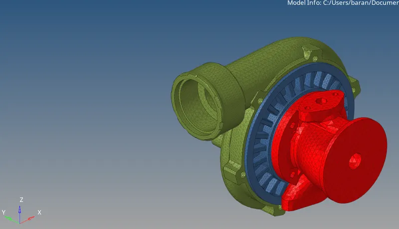
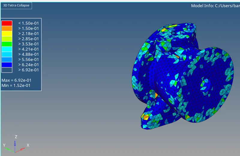
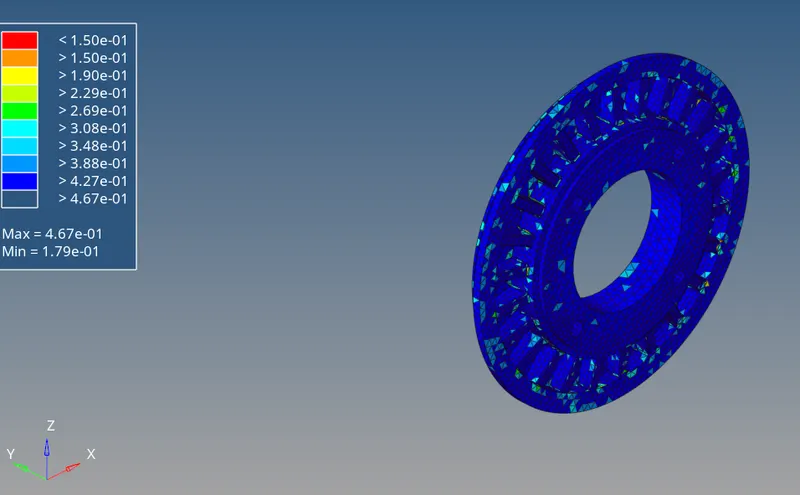
TET Collapse Maps and distribution are shown below,
For the Entire Model-3 the TET Colapse distributio is shown below. The minimum Value of TET collapse is 0.151 > 0.150, Hence there are no elements failing for the TET collapse.
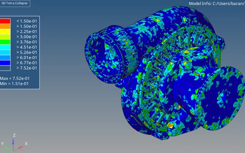
Casing TET collapse Mapping:
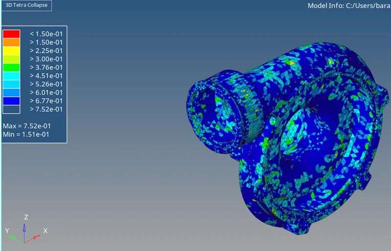
Holder Housing TET collapse Mapping:
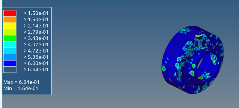
HUB Tet Collapse Mapping:
Supporting Plate TET collapse mapping:
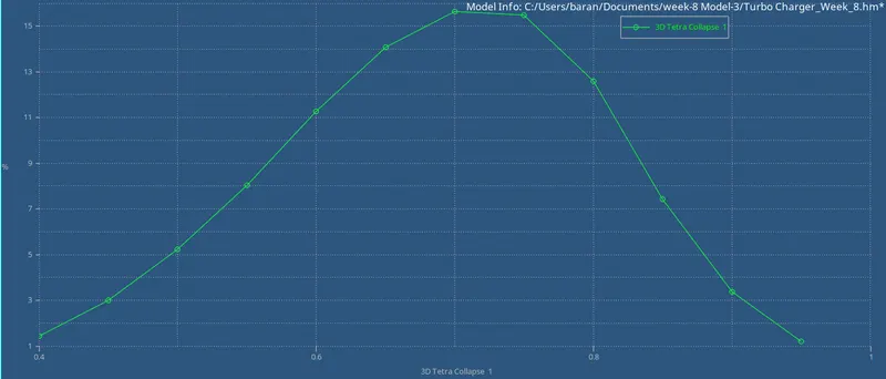
Overall Distribution of TET collapse for Model-3
From below distribution we can clearly see that the 75% of elements in the FEA model is in the TET collapse range of 0.6 to 0.9
learning Outcomes:
1. Different methods to create Tetra mesh is learned.
2. Out of different methods 2D to 3D Conversion method is found to be best, as we can easily control the mesh and properly capture the Features without much increase in the element count.
Conclusion:
The Tetra meshing is created for the given components.